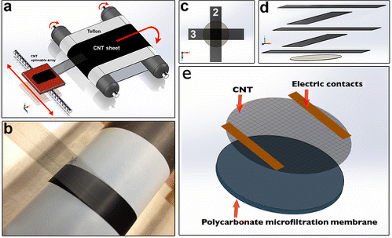
Figure 1.
CNT/PC membrane assembly process: (a) scheme that shows CNT sheet being drawn from a spinnable array, collected on a Teflon™ belt. This process can be conducted at drawing speeds of 16 m s−1; (b) picture of the CNT sheet assembly and film collection on a Teflon™ drum; (c) arrangement and (d) assembly of five alternating perpendicular layers of CNT ribbon drawn and laid onto the surface of a polycarbonate microfiltration membrane (1 μm pore size). Three layers run along the conductive axis of alignment and complete the resistive heating circuit, while the other two layers run along the supportive axis and maintain the structure. Two pieces of copper tape served as electrodes and were placed on top; (e) graphic representation of CNT membrane assembly and components.

