Abstract
In recent times, flexible piezoresistive polymer nanocomposite-based strain sensors are in high demand in wearable devices and various new age applications. In the polymer nanocomposite-based strain sensor, the dispersion of conductive nanofiller remains challenging due to the competing requirements of homogenized dispersion of nanofillers in the polymer matrix and retaining of the inherent characteristics of nanofillers. In the present work, waterproof and flexible poly(vinylidene difluoride) (PVDF) with a polymer-functionalized hydrogen-exfoliated graphene (HEG)-based piezoresistive strain sensor is developed and demonstrated. The novelty of the work is the incorporation of polystyrene sulfonate sodium salt (PSS) polymer-functionalized HEG in a PVDF-based flexible piezoresistive strain sensor. The PSS-HEG provides stable dispersion in the hydrophobic PVDF polymer matrix without sacrificing its inherent characteristics. The electrical conductivity of the PVDF/PSS-HEG-based strain sensor is 0.3 S cm–1, which is two orders of magnitude higher than the PVDF/HEG-based strain sensor. Besides, near the percolation region, the PVDF/PSS-HEG shows a maximum gauge factor of 10, which is about two times higher than the PVDF/HEG-based flexible strain sensor and 5-fold higher than the commercially available metallic strain gauge. The enhancement in the gauge factor is due to the stable dispersion of PSS-HEG in the PVDF matrix and electron conjugation caused by the adherence of negatively charged sulfonate functional groups on the HEG. The developed waterproof flexible strain sensor is demonstrated using portable wireless interfacing device for various applications. This work shows that the waterproof flexible PVDF/PSS-HEG-based strain sensor can be a potential alternative to the commercially available metallic strain gauge.
1. Introduction
Sensors play a crucial role in designing the smart electronic devices and its demands are increasing enormously in the past decade in a plethora of applications such as wearable devices, internet of things, and virtual reality. The need of the strain sensor is substantial in measuring the mechanical movement or deformation of any system. There are various types of readout mechanism for electromechanical strain sensors that are explored such as capacitance,1 inductance,2 and piezoresistance.3 Even though electromechanical capacitance- and inductance-based strain sensors are introduced, response to vibration, complex integrated circuits, and requirements in mounting the sensor limit their commercial usage. For that, the commercially viable piezoresistive metallic strain gauge has been introduced with a gauge factor of ∼2, and it is highly functional in structural health monitoring (SHM) applications. However, in SHM application, the bridges and megastructures are prone to different weather conditions, in particular moisture. For such applications, a sensor with an inherent waterproof feature is the most recognizable. Besides, new applications like wearable devices demand a high gauge factor along with the features like flexibility, waterproofness, and robustness.
To design such a sensor, polymer nanocomposite is one of the ideal solutions. In this regard, researchers have explored different polymer matrixes and conductive nanofillers. The literature encompasses various polymer matrixes such as poly(vinylidene difluoride) (PVDF),4−6 poly(methyl methacrylate) (PMMA),7,8 polydimethylsiloxane (PDMS),9−11 epoxy,12 polyvinyl alcohol (PVA),13 polyaniline (PANI),14 and polyethylene terephthalate (PET)15 to cite a few. Among the various polymers, PVDF is an inherent piezo material with good mechanical strength and hydrophobic in nature.16 Similarly, researchers are exploring novel nanomaterials like carbon nanotube (CNT),17,18 graphene,19 and silicon nanowires (SiNWs).20,21 Due to the exemplary electrical, mechanical, and thermal properties, graphene can be used as a conductive nanofiller in the development of a flexible strain sensor. In PVDF-based polymer nanocomposite piezoresistive strain sensors,22−25 PVDF with CNTs are explored in detail,22,24,25 whereas PVDF with the graphene-based strain sensor is less probed and also not comprehensive.23
The performance of the polymer nanocomposite-based flexible strain sensor depends upon many parameters such as nanofiller’s dispersion, conductivity, and volume fraction in the polymer matrix. Among these, dispersion of nanofillers is a key parameter, which influences the rest of the parameters, and it is a challenging task to achieve the stable dispersion of nanofillers in the polymer matrix. Due to the high surface energy and π–π interactions of graphene sheets, it tends to agglomerate in the polymer matrix, which hinders the formation of the conducting network, and thus, it affects the enhancement of the electrical conductivity of the polymer nanocomposite.26
Functionalization of graphene either with acid (covalent) or polymer (noncovalent) prevents the restacking of graphene sheets and hence the agglomeration in the polymer matrix.27 Although the conventional acid functionalization prevents the agglomeration, the acid disrupts the π–π conjugation of graphene sheets and causes the defects in the structure, which affects the electrical characteristics of the graphene,27,28 whereas the polymer functionalization prevents the agglomeration without sacrificing the inherent electrical conductivity of graphene.29−32 Functionalization of nanomaterials with positive, negative, and neutral polyelectrolytes is reported for various applications such as the supercapacitor,33 metal-free electrocatalyst,34,35 and exfoliation of graphite oxide,36 and it showed enhanced performance. The choice of the functionalization charge depends upon on the requirement of the application. To prevent the agglomeration of nanofillers, the functionalization charge should be the same as the intrinsic surface charge of the nanofillers. Since, in the present work, the surface of the graphene nanofiller is accumulated with a negative charge from the hydroxyl and carboxyl functional groups, the anionic polyelectrolyte has to be chosen for the functionalization. Among various anionic polyelectrolytes such as carboxylate, phosphonate, and sulfonate, one of the strong and common anionic polystyrene sulfonate sodium salt (PSS) is used for the functionalization of graphene.37 PSS-functionalized carbon nanomaterials are used for enhancement of dispersion in polymer solar cells38 and different nanocomposites,26,39,40 which shows the enhanced performance. Herein, we are the first to report the influence of polymer functionalization on the performance of the flexible piezoresistive strain sensor.
In the present work, a waterproof flexible PVDF with the polymer-functionalized graphene-based piezoresistive strain sensor is developed. PVDF polymer is used as the base matrix, and polystyrene sulfonate sodium salt (PSS) is used for the functionalization of nanofillers. We have prepared the flexible polymer free-standing film with varying weight percentages of PSS-HEG nanofillers in the PVDF matrix and tested for the strain measurement. To understand the role of PSS functionalization, strain measurement of HEG in the PVDF polymer matrix is also carried out. When compared to the pristine HEG, PSS-functionalized HEG (PSS-HEG) shows better dispersion, which helps in the firm formation of the electrical conducting network and thus increases the electrical conductivity of the strain sensor. The results show that electrical conductivity of the PVDF/PSS-HEG is two orders of magnitude higher than the PVDF/HEG-based flexible strain sensor. As a resultant, the gauge factor of PVDF/PSS-HEG is about 2.3 times higher than the PVDF/HEG-based strain sensor. Besides, the portable wireless interfacing device is designed, and the potential of the PVDF/PSS-HEG-based strain sensor is tested for different applications.
2. Results and Discussions
2.1. Physical Characterization
The crystalline nature of the prepared sample is studied using the X-ray diffraction (XRD) technique (Figure 1a). Transformation of graphite oxide (GO) to HEG reduces the number of layers, which make the graphitic peak broader from 15 to 30°.41 It can be noted that the d spacing of the HEG is reduced to 0.36 nm due to the removal of oxygen content from the interlayers.41 When compared to the pristine HEG, a left shift of 0.6° is observed in PSS-HEG, which is attributed to the attachment of PSS functional groups.40 The overlapped diffraction peaks of the solution-casted PVDF/PSS-HEG nanocomposite film at 18.5 and 20.6° correspond to the PVDF matrix.42 Since the PSS-HEG nanofiller is 1 wt % in the nanocomposite film, its peaks are not prominent in the XRD.
Figure 1.
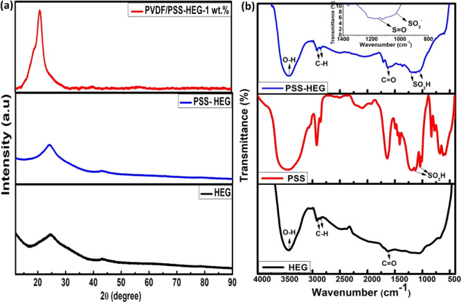
(a) X-ray diffraction pattern of PVDF powder, HEG, PSS-HEG, and solution-casted PVDF/PSS-HEG-1 wt % nanocomposite film and (b) FTIR spectrum of HEG, PSS, and PSS-HEG.
Functional groups present in the HEG nanofillers can be confirmed with the FTIR spectrum, and it is illustrated in Figure 1b. The signals of −OH, CHx antisymmetric and symmetric stretching, and C=O carboxyl groups are observed at 3440, 2920, and 1628 cm–1, respectively. The fingerprint of SO3H in sulfonic acids with S=O stretch and SO3 symmetric stretch is shown in the inset of Figure 1b at 1170 and 1040 cm–1, respectively, which confirms the PSS functionalization of HEG. The anionic sulfonate functional group on the HEG helps in preventing the restacking of graphene, and implication of this property has been explained later.
The dispersion of the HEG as well as PSS-HEG nanofillers in the solution is quantitatively analyzed using zeta potential distribution. The analysis is carried out in DMF solvent, which is used in the preparation of the flexible strain sensor, with a pH value of 6.5, and the results are shown in Figure 2a. The zeta potential distribution values of the pristine HEG and PSS-HEG are −35.9 and −46.6 mV, respectively. The increment in magnitude of zeta potential confirms that the PSS-HEG is a more stable solution than the pristine HEG. The higher magnitude of the zeta potential with the same negative sign attributes to the accumulation of a more negative charge over the nanofillers, and it also confirms the anionic PSS functionalization over the HEG. The stability of the solution has been tested by keeping the solution undisturbed over 30 days, and the results shown in Figure 2b,c confirm that PSS-HEG is more stable than the pristine HEG. This is due to the prevention of restacking of the HEG, which is caused by the adherence of negatively charged sulfonate functional groups on the HEG. This PSS-HEG dispersion stability helps in the firm formation of the electrical conduction network in the polymer matrix, and thus, it enhances the electrical conductivity and the performance of the flexible strain sensor.
Figure 2.
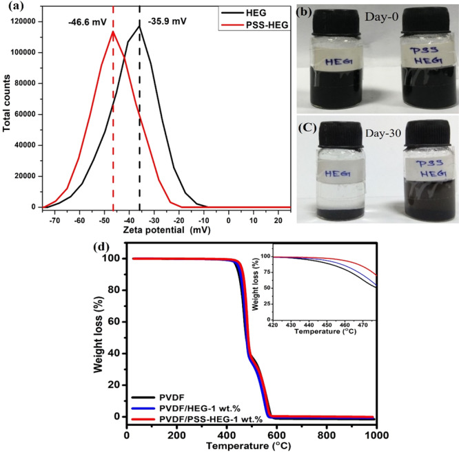
(a) Zeta potential distribution of pristine HEG and PSS HEG. Dispersion of pristine HEG and PSS-HEG on (b) day 0 and (c) day 30. (d) Thermogravimetric analysis of pristine PVDF, PVDF/HEG-1 wt %, and PVDF/PSS-HEG-1 wt %.
The effect of temperature on the stability of PVDF with the graphene polymer nanocomposite film is studied using thermogravimetric analysis (TGA). Figure 2d shows the weight loss profile of pristine PVDF-, PVDF/HEG-, and PVDF/PSS-HEG-based strain sensor films. All the three-solution-casted PVDF nanocomposite films are observed to be decomposed at different temperatures. To understand the effect of addition of the HEG nanofiller on thermal stability of the PVDF nanocomposite, their heat resistance index (THRI) is calculated and illustrated in Table 1. When adding 1 wt % PSS-HEG nanofillers in the PVDF matrix, it is evident that compared to the pristine PVDF film, the heat resistance index is increased by 3%, which is attributed to the interaction between the nanofiller and the PVDF polymer matrix.43,44 Also, from the inset figure (Figure 2d), PVDF/PSS-HEG shows relatively better thermal stability when compared to the pristine PVDF and PVDF/HEG polymer nanocomposite films.
Table 1. Thermal Decomposition of the PVDF Nanocomposite-Based Flexible Strain Sensor.
| polymer nanocomposites | T5% (°C) | T30% (°C) | THRI (°C)a |
|---|---|---|---|
| PVDF | 438.96 | 466.31 | 223.1 |
| PVDF/HEG | 446.51 | 470.4 | 225.8 |
| PVDF/PSS-HEG | 456.61 | 477.6 | 229.9 |
THRI = 0.49 [T5% + 0.6 (T30% – T5%)],45 where T5% and T30% are decomposition temperatures for 5% and 30% weight loss, respectively.
The morphologies of the prepared samples are investigated using the transmission electron microscopy (TEM) technique. The TEM image of pristine HEG shown in Figure 3a illustrates that layers of the pristine HEG are highly wrinkled and disordered in nature. The TEM image of PSS-HEG (Figure 3b) confirms that exfoliated graphene sheets and the process of functionalization do not affect the morphology of hydrogen-exfoliated graphene.26 The prepared polymer nanocomposite film is analyzed using a scanning electron microscope (SEM). Figure 3c–e) shows top view and cross-sectional view of the PVDF/PSS-HEG-based film, and it illustrates the homogenized mixture of the PSS-HEG nanofiller in the PVDF base matrix. The small pore appears in the top view of the PVDF/PSS-HEG (Figure 3c) due to the evaporation of the DMF solvent during the solution casting process. From the cross-sectional view (Figure 3d) of the sensor, it is apparent that the thickness of the sensor is uniform and its average thickness is 145 ± 4 μm. Figure 3e shows the zoomed-in version of the cross-sectional view, and the homogenized dispersion of the HEG nanofiller in the PVDF matrix is evident.
Figure 3.
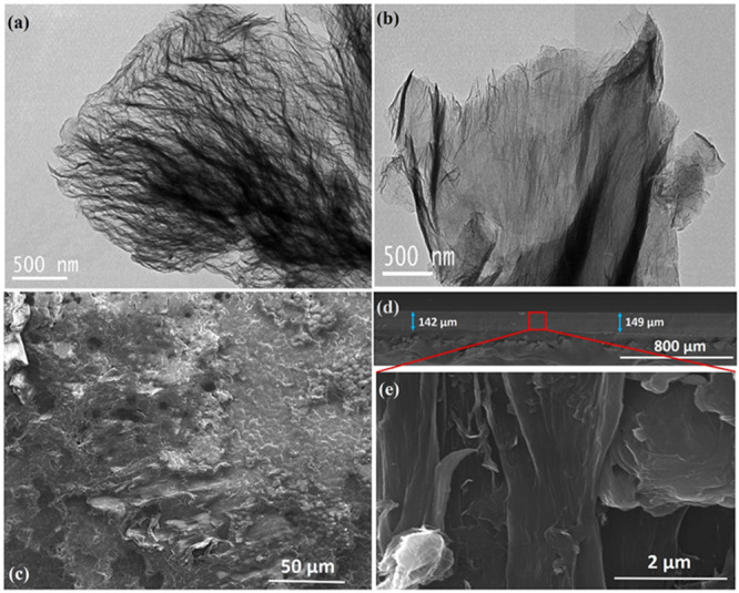
TEM images of (a) pristine HEG and (b) PSS-HEG. SEM image of PVDF/PSS-HEG (c) top view, (d) cross sectional view, and (e) zoomed-in version of the cross-sectional view.
2.2. Mechanical Measurement
The mechanical characteristics of the developed flexible strain sensors are tested by using a microtensile measurement unit. The as-prepared PVDF nanocomposites are cut into rectangular films with a dimension of 30 mm × 10 mm. The films are fixed at edges with a gripping area of 6 × 10 mm2 using fine sandpaper. The axial tensile force is applied to the as-prepared film with a strain rate of 0.1 mm min–1, and the corresponding stress is measured by the load cell connected in the machine. The strain experienced by the film is measured from the crosshead displacement normalized with the gauge length of the test specimen. The stress–strain characteristics of both PVDF/HEG- and PVDF/PSS-HEG-based strain sensors with different concentrations from 0.5 to 7 wt % are shown in Figure 4a,b, respectively. From the results, it is identified that as the nanofiller concentration increases in the PVDF polymer matrix, the elastic modulus of the composite decreases and also reported in the literature.46 For instance, the maximum decrement in the elastic modulus of PVDF/PSS-HEG-7% is 13.3% lesser when compared to the pure PVDF film. This signifies that the introduction of carbon nanofillers in the polymer matrix reduces the elasticity of the polymer nanocomposite and hence, the reduction in the maximum strain of a PVDF nanocomposite film can withstand. Thus, it is better to design the flexible strain sensor with less nanofiller concentration. While comparing pristine HEG and PSS-HEG, as the concentration of nanofiller increases, the elastic modulus of PVDF/PSS-HEG-based films reduces regularly when compared to the PVDF/HEG-based films. The rationale for this difference is the uniform dispersion of PSS-HEG in the PVDF polymer matrix when compared to pristine HEG.
Figure 4.
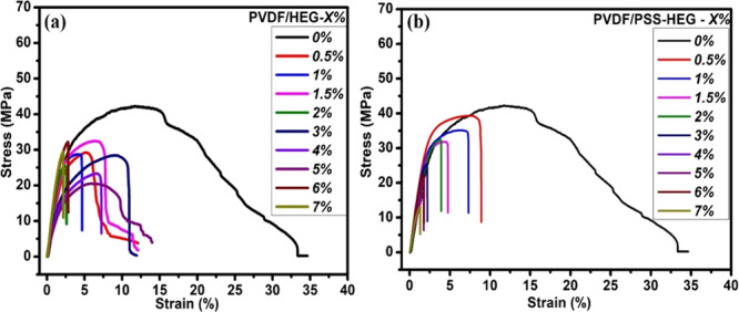
Stress–strain characteristics of as-prepared polymer nanocomposites (a) PVDF/HEG and (b) PVDF/PSS-HEG with different nanofiller concentrations.
2.3. Electrical Conductivity Measurement
As a function of nanofiller concentration in the polymer nanocomposite, electrical conducting network formation can be quantified by the four-probe electrical resistance (R) measurement. Since the prepared film thickness (t) is ∼0.14 mm, which is very much lesser than spacing (S) between the four probes (2 mm), the DC electrical conductivity (σ) of the film is calculated by using eq 1
| 1 |
The DC electrical conductivity of the PVDF nanocomposite film with varying concentrations of pristine HEG and PSS-HEG from 0.5 to 7 wt % PVDF is shown in Figure 5, and it is given in Table S1. According to the percolation theory, the variation in the electrical conductivity of the polymer nanocomposites follows the power law as it approaches the percolation threshold and it is governed by eq 2(47)
| 2 |
where σ is the electrical conductivity of the polymer nanocomposites, σ0 and t are the fitted constants, ϕ is the volume fraction of the nanofiller, and ϕC is the volume fraction of the nanofiller at the percolation point. The electrical conductivity of the polymer nanocomposite against (ϕ – ϕC) is shown in Figure 5 as inset. From the inset of Figure 5, the percolation threshold (ϕC) of the PVDF/HEG is 4 wt % and for the PVDF/PSS-HEG, the percolation threshold is 1.5 wt %, where the electrical conductivity of the polymer nanocomposite begins to increase. This signifies that adding polymer-functionalized PSS-HEG can achieve higher electrical conductivity with lesser loading of nanofillers. The additional advantage of lesser loading is avoiding poor processability and inferior mechanical properties.48−50 In the case of PVDF/HEG, from 4 wt %, the electrical conductivity starts to enhance, reaches 10–3 S cm–1 at 5 wt %, and saturates beyond that point where the electrical conducting network is firmly formed, whereas in the case of PVDF/PSS-HEG, from 1.5 wt %, the electrical conductivity of the film enhances, reaches 10–1 S cm–1 at 4 wt %, and gets saturated. The maximum electrical conductivity of the PVDF/PSS-HEG strain sensor film is observed to be 0.3 S cm–1, which is two orders of magnitude higher than the PVDF/HEG-based flexible strain sensor. When comparing the overall trend of the electrical conductivity of the pristine HEG and PSS-HEG, it can be observed that there is tottering in the pristine HEG profile, which is due to the agglomeration of the pristine HEG in the PVDF matrix. The steady transition and enhanced electrical conductivity of the PSS-HEG are due to the stable dispersion of PSS-HEG and electron conjugation caused by attachment of PSS functional groups on the HEG.26
Figure 5.
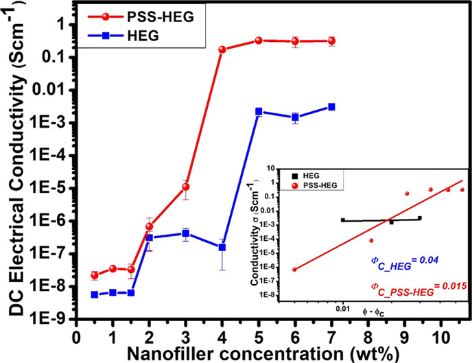
Electrical conductivity of the PVDF/HEG and the PVDF/PSS-HEG with varying concentrations. Inset figure shows the relationship between (ϕ – ϕC) and conductivity of HEG and PSS-HEG in the PVDF polymer matrix.
2.4. Electromechanical Measurement
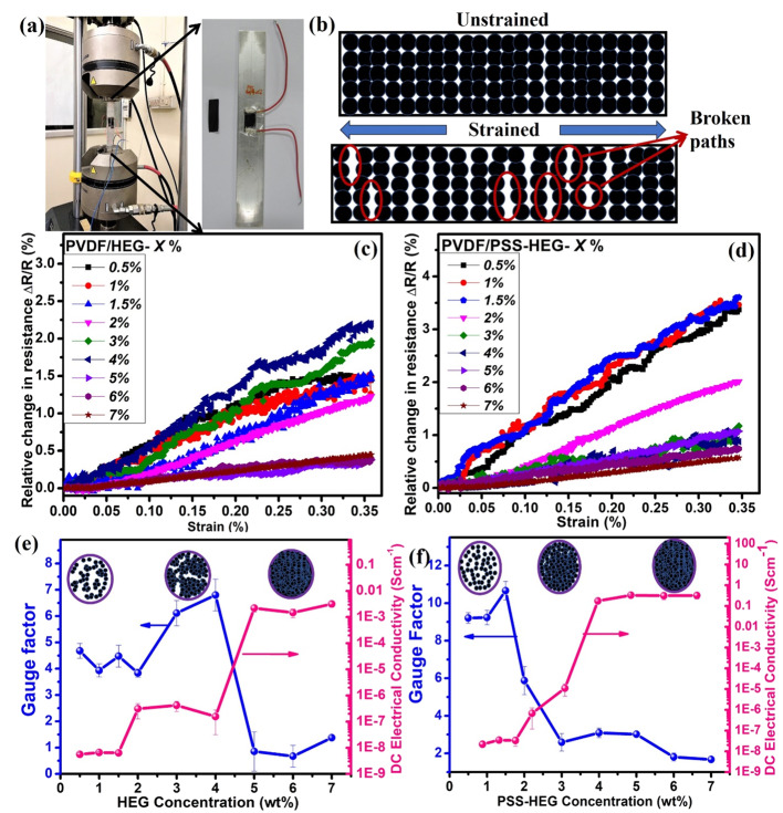
The prepared film is fabricated on the aluminum specimen and tested for piezoresistive characteristics by applying uniaxial tensile force to the aluminum specimen. The maximum load, which can be applied for tensile testing is determined by the elastic limit of the specimen under investigation. For instance, the elastic limit of the aluminum is 280 MPa.51 Hence, the fabricated aluminum specimen is mechanically strained to a maximum tensile load of 160 MPa with a strain rate of 1 mm min–1 using a uniaxial tensile machine, as shown in Figure 6a. As a resultant of applied tensile force, the aluminum specimen experiences the strain (ε) and it is transmitted to the bonded flexible strain sensor in which electrical conductive network formed by the HEG nanofillers gets distorted. The schematic of breaking of the conducting network of the polymer nanocomposite under strain is shown in Figure 6b. The breaking of the conducting network leads to the change in resistance of the strain sensor, which is simultaneously measured using a Keithley 2450 source measurement unit. The relative change in resistance (ΔR/R) of all the prepared flexible strain sensors is measured against the applied strain as a function of concentration of the pristine HEG and PSS-HEG in the PVDF polymer matrix and is shown in Figure 6c,d, respectively. The linear responses between the relative change in resistance and the applied strain confirm the linearity of the flexible piezoresistive strain sensor. The slope values of both the PVDF/HEG and the PVDF/PSS-HEG strain sensors are high in less nanofiller concentration and decreased in high nanofiller concentration. The rationale for this variation in slope is stated in detail below.
Figure 6.
(a) Piezoresistive measurement of the fabricated strain sensor on the aluminum specimen, which is under uniaxial tensile loading. (b) Schematic of unstrained and strained polymer nanocomposites, which illustrates the breaking of the conducting path under strain. Relative change in resistance against applied strain for (c) PVDF/HEG and (d) PVDF/PSS-HEG. Gauge factor and DC electrical conductivity of (e) PVDF/HEG- and (f) PVDF/PSS-HEG-based strain sensors for different concentrations of HEG and PSS-HEG nanofillers, respectively.
The slope of the relative change in resistance for the applied strain, called as the gauge factor, is an evaluating parameter of the performance of the strain sensor, which is governed by eq 3.52
| 3 |
The gauge factor values of the PVDF/HEG and the PVDF/PSS-HEG for various concentrations ranging from 0.5 to 7 wt % are shown in Figure 6e,f, respectively. The gauge factor trend of both pristine HEG- and PSS-HEG-based nanocomposite films signifies that the performance of the strain sensor is higher at the low concentration when compared to the higher concentration of the HEG nanofillers. The rationale for a high gauge factor at lower concentration is sparsely formed the electrical conducting network. While applying the tensile force to the film, electron transfer paths got cracked and thus lead to increase in the change in resistance. As the concentration of both pristine HEG and PSS-HEG nanofillers increases in the polymer matrix, sudden decrement in the magnitude of the gauge factor is observed and saturates beyond that point. At a higher concentration of HEG, a highly dense and firm electrical conducting network is formed. Hence, while applying tensile load to the firmly formed electrical network, breaking of the conducting network is insignificant. Therefore, the electron transfer path is not hindered much, which results in the insignificant change in resistance and subsequently results in a low gauge factor.
However, while comparing the performance of pristine HEG-and PSS-HEG-based flexible strain sensors, the gauge factor profile of the pristine HEG is tottering due to the agglomeration of the pristine HEG nanofillers in the polymer matrix. The agglomeration is because of high surface energy and π–π interactions of graphene sheets of the nanofillers, which tend to attract the nearby nanofillers,26 whereas in the PSS-functionalized HEG, the adherence of the negative charge on the HEG strongly repels each other and prevents PSS-HEG nanofillers from restacking and making the electrical conducting network formation more stable. Since the formation of electrical conducting network is enhanced, it reflects in smooth and high change in resistance for the applied strain. As a resultant, the PSS-HEG-based strain sensor shows a gauge factor of 10, which is 2.3 times higher when compared to the pristine HEG-based strain sensor.
Figure 6e,f also signifies the correlation between the DC electrical conductivity and the gauge factor of the PVDF/HEG- and PVDF/PSS-HEG-based flexible strain sensors, respectively. In both cases, the gauge factor profile of the strain sensor is converse to the DC electrical conductivity profile. From the results, it is evident that the gauge factor is relatively higher near to the percolation region, at which the DC electrical conductivity starts to rise. As the electrical conductivity increases with the increase in HEG concentration, the gauge factor drops down. This is because of insignificant breaking of the electron transfer path for the applied strain. The tottering in both electrical conductivity and gauge factor profile of PVDF/HEG is due to the agglomeration of HEG in the PVDF matrix, whereas in PVDF/PSS-HEG, a relatively steady profile is observed, which is attributed to the stable dispersion of PSS-HEG in the PVDF matrix.
To analyze the repeatability and cyclic stability, the commercial metallic strain gauge (HBM1-LY416/350) and the developed flexible strain sensor are fabricated on the aluminum specimen and applied cyclic loading using a uniaxial tensile testing machine.53,54 In this process, load is applied in the following way. As shown in Figure 7a, in the initial 15 s, no load is applied and then a cyclic load of 10 kN is applied for 50 cycles with a frequency of 0.1 Hz (500 s), and no load is applied for final 15 s. The dynamic responses of the PVDF/PSS-HEG-1.5%-based strain sensor and the commercial metallic strain gauge for the applied cyclic loading are shown in Figure 7b. The continuous change in resistance of the strain sensors is observed according to loading and unloading of 50 cycles. Dynamic results shown in Figure 7b ensure that the relative change in resistance of the PVDF/PSS-HEG flexible strain sensor is higher when compared to the commercial metallic strain gauge. The result also confirms the repeatability and cyclic stability of the flexible strain sensor.
Figure 7.
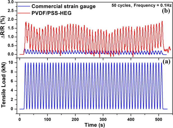
(a) Applied tensile cyclic load of 10 kN for 50 cycles with a frequency of 0.1 Hz and (b) response of the PVDF/PSS-HEG-1.5 wt%-based flexible strain sensor and commercial metallic strain gauge for the applied cyclic loading.
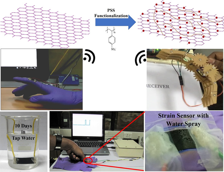
Since the developed flexible strain sensor finds applications in structural health monitoring and wearable devices, which may undergo different weather conditions, it is more important to test the sensor for the water-resistant feature. In this regard, the developed PVDF/PSS-HEG-5%-based flexible strain sensor is fabricated with an electrode using silver paste and passivated it with silicone gel. As shown in Figure 8a, the fabricated sensor is immersed in the water for 10 days and found out that there is no change in nominal resistance of the film (5.6 kΩ). Besides, the working model of the developed flexible strain sensor is demonstrated in the presence of water, which confirms the waterproof feature (Figure 8b), and the demonstration video is given in the Supporting Information (Video S3). This water-resistant feature is attributed to the hydrophobicity of the PVDF polymer matrix.
Figure 8.
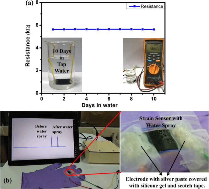
(a) Electrical resistance of the flexible strain sensor, which is immersed in water over the period of 10 days. (b) Response of the flexible strain sensor for the applied strain before and after the water spray, and inset figure shows the zoomed-in view of the presence of water droplets on the strain sensor.
2.5. Design of Portable Interfacing Circuit
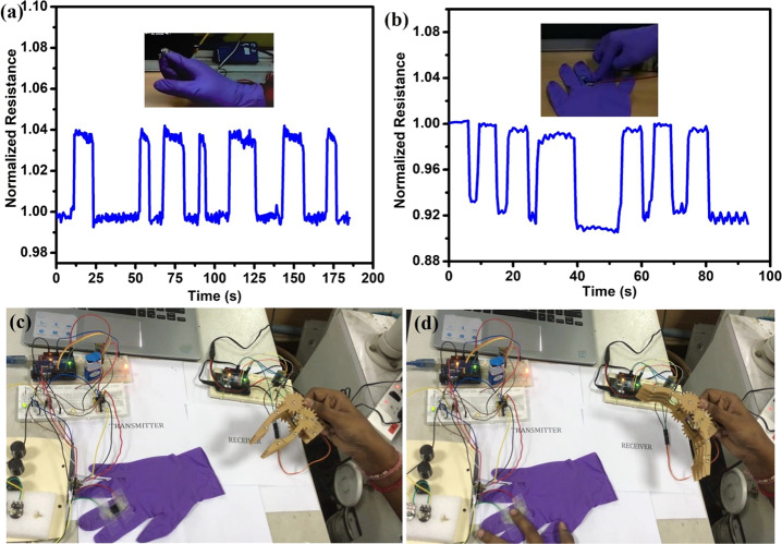
The developed flexible strain sensor is pasted on the hand gloves for demonstration of wearable applications. Figure 9a,b shows the resistance change for the detection of strain caused by bending of the finger and pressing, respectively. In addition, we have designed both wired and wireless-enabled portable interfacing devices for communicating between the flexible strain sensor and the data acquisition center. The wireless interfacing device at the transmitter side comprises of a flexible strain sensor connected in a Wheatstone bridge, instrumentation amplifier (INA125), and microcontroller (ATmega328P), which has an inbuilt 10-bit analog to digital converter (ADC). This inbuilt ADC converts the flexible strain sensor’s analog value into digital data, which is mapped into a range of 5 V through programming. The strain sensor’s data is transmitted through the wireless trans-receiving module (HT-05). At the receiver side, the received data can be used to monitor the output signal, and the same can be used to control any of the actuator simultaneously. For instance, we have demonstrated the wireless controlling of robotic arm using the developed PVDF/PSS-HEG flexible piezoresistive strain sensor, it is shown in Figure 9c,d, and demonstration video is in the Supporting Information (Video S2). The schematics and the circuit details of the interfacing device are given in the Supporting Information (Figure S2). These demonstrations depict the potential of the developed flexible strain sensor, and it can be extended to the various applications such as biofunctional prosthetic limbs, human activity monitoring, and health care.
Figure 9.
Demonstration of the flexible strain sensor for wearable device applications. (a) Finger bending and (b) pressing. Controlling of robotic arm using the strain sensor (c) unstrained and (d) strained positions.
3. Conclusions
In this present work, we have developed and demonstrated the waterproof flexible polymer-functionalized HEG-based polymer nanocomposite piezoresistive strain sensor along with the wireless portable interfacing device. The systematic study is carried out to analyze the influence of the PSS functionalization of HEG on the electrical conductivity and the performance of the flexible piezoresistive strain sensor. PSS-HEG shows a stable dispersion in the PVDF matrix when compared to pristine HEG, leading to enhanced electrical conductivity resulting in a high gauge factor. The electrical conductivity of PVDF/PSS-HEG-7 wt % is 0.3 S cm–1, which is two orders of magnitude higher than the PVDF/HEG-based flexible strain sensor. Besides, near the percolation region, the maximum gauge factor shown by PVDF/PSS-HEG-1.5 wt % is 10, which is 2.3 times higher than the PVDF/HEG-based strain sensor and 5-fold higher than the commercially available metallic strain gauge. PSS-HEG thus enhances the dispersion without sacrificing the inherent characteristics, thereby helping to achieve a high gauge factor in less concentration of nanofillers in the flexible polymer nanocomposite-based piezoresistive strain sensor. Also, the developed flexible strain sensor is demonstrated for controlling of robotic arm using the developed portable wireless interfacing device for the wearable electronics applications. This polymer-functionalized HEG-based waterproof flexible piezoresistive strain sensor can be the potential alternative for the commercially available metallic strain gauge.
4. Experimental Section
4.1. Characterization Techniques
X-ray diffraction for the prepared material is analyzed using a D8 ADVANCE Bruker X-ray diffractometer with Cu Kα radiation (λ = 0.15418 nm) with a range of 5–90° with a step size of 0.02°. Fourier transform infrared (FTIR) spectroscopy is measured using PerkinElmer Spectrum One FTIR instrument with a scan range of 450–4500 cm–1 and a resolution of 1 cm–1. Zeta potential measurement is carried out in a Malvern Panalytical Zetasizer Nano ZS90 instrument using a universal dip cell (ZEN1002) in a quartz square aperture cuvette. Thermal stability is analyzed using a thermogravimetric analysis (TGA) SDTQ600 analyzer from TA instruments, with a temperature range from room temperature to 1000 °C with a heating rate of 20 °C min–1 in an air atmosphere (160 mL min–1). Morphology of the samples are captured using a transmission electron microscope (TEM) Tecnai G2 T20 instrument by drop-casting the sample prepared with ethanol on the holey carbon coated 200 mesh copper grids. A scanning electron Microscope (SEM) Quanta 200 is used to capture the morphology of the polymer nanocomposite films. The electrical conductivity of the film is tested using a four-probe setup with an inter probe distance of 2 mm connected with a Keithley 2400 source measurement unit controlled by LabVIEW software. Strain measurement is carried out using an Instron 8501 uniaxial tensile machine with a maximum load of 15 kN and a strain rate of 1 mm min–1.
4.2. Preparation of HEG
For the preparation of hydrogen-exfoliated graphene (HEG), the graphitic oxide (GO) is prepared using the modified Hummers method.55 Briefly, pure graphite powder is added to the concentrated H2SO4, which is kept in an ice bath. The oxidizing agents such as sodium nitrate (NaNO3) and KMnO4 are added in a ratio of 1:6 to the solution slowly with high care. Take out the sample from ice bath and allow it to cool down to room temperature along with stirring. Then, DI water is added drop by drop followed by the addition of 12 mL of hydrogen peroxide (H2O2). Wash and filter the solution until it reaches the neutral pH and dry in a vacuum oven at 60 °C.
For the preparation of hydrogen-exfoliated graphene, the GO is heated at 200 °C in the tubular furnace in the presence of hydrogen and argon gas, which resulted in the few-layered reduced graphene oxide.41
4.3. Polymer Functionalization
The calculated quantity of 1 M NaCl and HEG is added in DI water and ultrasonicated for 1 h. Polystyrene sulfonate sodium salt (PSS) is added twice the amount of nanofillers and sonicated for 1 h. The final solution is filtered several times and dried at 60 °C for 12 h.56
4.4. Synthesis of Polymer Nanocomposite
PVDF is added in dimethylformamide (DMF) and sonicated until it dissolves completely. Based on the weight percent, PSS-HEG is added to the DMF and sonicated for 1 h separately. Then, both solutions are mixed and sonicated for 1 h. For further homogenization, the solution is blended in a shear mixer for 3 h at 3500 rpm. Finally, to get a free-standing and flexible film, the solution is casted in a petri dish over night at 50 °C. The schematic of the synthesis process is shown in Figure S1c.
4.5. Sensor Fabrication and Testing
The prepared film is sliced into a particular dimension (3 cm × 1 cm) and pasted on the ASTM standard aluminum specimen (14 × 3 × 3 cm3) using epoxy, and electrical contacts are taken at the edges of the film using conductive silver paste, as shown in Figure S1f, and kept it 24 h for drying at room temperature. The maximum load, which can be applied for testing is determined by the elastic limit of the specimen under investigation. For instance, the elastic limit of the aluminum is 280 MPa.51 Hence, the fabricated aluminum specimen is mechanically strained to a maximum tensile load of 160 MPa with a strain rate of 1 mm min–1 using a uniaxial tensile machine, as shown in Figure S1f. The resultant change in the electrical resistance value is simultaneously measured using a Keithley 2450 source measurement unit.
Acknowledgments
The authors would like to thank Department of Science and Technology (DST) and Tata Steel for the financial support under Uchhatar Avishkar Yojana (UAY) scheme through a project and IIT Madras, India, for supporting this work. The authors acknowledge SAIF, IITM for FTIR measurements. The authors would like to thank DST for the microtensile measurement through DST-FIST (SR/FST/ETI-059/2013). A patent has been filed on “Strain sensor for wearable electronics and method of preparation thereof” with R.S., K.B., and V.S. (ref. 201941015175) by Indian Institute of Technology Madras.
Supporting Information Available
The Supporting Information is available free of charge at https://pubs.acs.org/doi/10.1021/acsomega.9b04205.
Schematic of PSS polymer functionalization of the HEG, schematic of dispersion of pristine HEG and PSS-HEG in the PVDF matrix, synthesis procedure of PVDF/HEG polymer nanocomposite-based free-standing flexible strain sensor, and digital image to show the flexibility and robustness of the developed strain sensor and fabricated strain sensor on the aluminum specimen, which is under uniaxial tensile loading (Figure S1a–f); schematic of the wireless portable interfacing unit, circuit diagram of the sensor interfacing and transmitting module, and circuit diagram of receiver module along with monitoring and alarming unit and actuator (robotic arm) (Figure S2a–c); and tabulation of electrical conductivity of the polymer nanocomposite films (Table S1) (PDF)
Demonstration of the flexible strain sensor for wearable applications (Video S1) (MP4)
Demonstration of wireless control of robotic arm (Video S2) (MP4)
Waterproof demonstration (Video S3) (MP4)
The authors declare no competing financial interest.
Supplementary Material
References
- Nesser H.; Grisolia J.; Alnasser T.; Viallet B.; Ressier L. Towards Wireless Highly Sensitive Capacitive Strain Sensors Based on Gold Colloidal Nanoparticles. Nanoscale 2018, 10, 10479–10487. 10.1039/c7nr09685b. [DOI] [PubMed] [Google Scholar]
- Christopoulos A.; Hristoforou E.; Koulalis I.; Tsamasphyros G. Inductive Strain Sensing Using Magnetostrictive Wires Embedded in Carbon Fibre Laminates. Smart Mater. Struct. 2014, 23, 085035 10.1088/0964-1726/23/8/085035. [DOI] [Google Scholar]
- Bardeen J.; Shockley W. Deformation Potentials and Mobilities in Non-Polar Crystals. Phys. Rev. 1950, 80, 72–80. 10.1103/PhysRev.80.72. [DOI] [Google Scholar]
- Yu G.-F.; Yan X.; Yu M.; Jia M.-Y.; Pan W.; He X.-X.; Han W.-P.; Zhang Z.-M.; Yu L.-M.; Long Y.-Z. Patterned, Highly Stretchable and Conductive Nanofibrous PANI/PVDF Strain Sensors Based on Electrospinning and in Situ Polymerization. Nanoscale 2016, 8, 2944–2950. 10.1039/c5nr08618c. [DOI] [PubMed] [Google Scholar]
- Kim S.; Dong Y.; Hossain M. M.; Gorman S.; Towfeeq I.; Gajula D.; Childress A.; Rao A. M.; Koley G. Piezoresistive Graphene/P(VDF-TrFE) Heterostructure Based Highly Sensitive and Flexible Pressure Sensor. ACS Appl. Mater. Interfaces 2019, 11, 16006–16017. 10.1021/acsami.9b01964. [DOI] [PubMed] [Google Scholar]
- Avilés F.; May-Pat A.; López-Manchado M. A.; Verdejo R.; Bachmatiuk A.; Rümmeli M. H. A Comparative Study on the Mechanical, Electrical and Piezoresistive Properties of Polymer Composites Using Carbon Nanostructures of Different Topology. Eur. Polym. J. 2018, 99, 394–402. 10.1016/j.eurpolymj.2017.12.038. [DOI] [Google Scholar]
- Wang J.; Hu H.; Wang X.; Xu C.; Zhang M.; Shang X. Preparation and Mechanical and Electrical Properties of Graphene Nanosheets–Poly(Methyl Methacrylate) Nanocomposites via In Situ Suspension Polymerization. J. Appl. Polym. Sci. 2011, 122, 1866–1871. 10.1002/app.34284. [DOI] [Google Scholar]
- Shi J.; Liu S.; Zhang L.; Yang B.; Shu L.; Yang Y.; Ren M.; Wang Y.; Chen J.; Chen W.; Chai Y.; Tao X. Smart Textile-Integrated Microelectronic Systems for Wearable Applications. Adv. Mater. 2019, 32, 1901958. 10.1002/adma.201901958. [DOI] [PubMed] [Google Scholar]
- Li Z.; Wang Y.; Xue X.; McCracken B.; Ward K.; Fu J. Carbon Nanotube Strain Sensor Based Hemoretractometer for Blood Coagulation Testing. ACS Sensors 2018, 3, 670–676. 10.1021/acssensors.7b00971. [DOI] [PMC free article] [PubMed] [Google Scholar]
- Wu S.; Peng S.; Wang C. H. Stretchable Strain Sensors Based on PDMS Composites with Cellulose Sponges Containing One- and Two-Dimensional Nanocarbons. Sens. Actuators, A 2018, 279, 90–100. 10.1016/j.sna.2018.06.002. [DOI] [Google Scholar]
- Yang T.; Jiang X.; Zhong Y.; Zhao X.; Lin S.; Li J.; Li X.; Xu J.; Li Z.; Zhu H. A Wearable and Highly Sensitive Graphene Strain Sensor for Precise Home-Based Pulse Wave Monitoring. ACS Sensors 2017, 2, 967–974. 10.1021/acssensors.7b00230. [DOI] [PubMed] [Google Scholar]
- Yang Y.; Chiesura G.; Plovie B.; Vervust T.; Luyckx G.; Degrieck J.; Sekitani T.; Vanfleteren J. Design and Integration of Flexible Sensor Matrix for in Situ Monitoring of Polymer Composites. ACS Sensors 2018, 3, 1698–1705. 10.1021/acssensors.8b00425. [DOI] [PubMed] [Google Scholar]
- Alexopoulos N. D.; Jaillet C.; Zakri C.; Poulin P.; Kourkoulis S. K. Improved Strain Sensing Performance of Glass Fiber Polymer Composites with Embedded Pre-Stretched Polyvinyl Alcohol-Carbon Nanotube Fibers. Carbon N. Y. 2013, 59, 65–75. 10.1016/j.carbon.2013.02.055. [DOI] [Google Scholar]
- Costa P.; Oliveira J.; Horta-Romarís L.; Abad M. J.; Moreira J. A.; Zapiráin I.; Aguado M.; Galván S.; Lanceros-Mendez S. Piezoresistive Polymer Blends for Electromechanical Sensor Applications. Compos. Sci. Technol. 2018, 168, 353–362. 10.1016/j.compscitech.2018.10.022. [DOI] [Google Scholar]
- Yeo J. C.; Kenry; Yu J.; Loh K. P.; Wang Z.; Lim C. T. Triple-State Liquid-Based Microfluidic Tactile Sensor with High Flexibility, Durability, and Sensitivity. ACS Sensors 2016, 1, 543–551. 10.1021/acssensors.6b00115. [DOI] [Google Scholar]
- Holmes-Siedle A. G.; Wilson P. D.; Verrall A. P. PVdF: An Electronically-Active Polymer for Industry. Mater. Des. 1983, 4, 910–918. 10.1016/0261-3069(84)90003-7. [DOI] [Google Scholar]
- Grow R. J.; Wang Q.; Cao J.; Wang D.; Dai H. Piezoresistance of Carbon Nanotubes on Deformable Thin-Film Membranes. Appl. Phys. Lett. 2005, 86, 1–3. 10.1063/1.1872221. [DOI] [Google Scholar]
- Yu M.-F.; Lourie O.; Dyer M. J.; Moloni K.; Kelly T. F.; Ruoff R. S. Strength and Breaking Mechanism of Multiwalled Carbon Nanotubes Under Tensile Load. Science 2000, 287, 637–640. 10.1126/science.287.5453.637. [DOI] [PubMed] [Google Scholar]
- Chen X.; Zheng X.; Kim J.-K.; Li X.; Lee D.-W. Investigation of Graphene Piezoresistors for Use as Strain Gauge Sensors. J. Vac. Sci. Technol., B: Nanotechnol. Microelectron.: Mater., Process., Meas., Phenom. 2011, 29, 06FE01 10.1116/1.3660784. [DOI] [Google Scholar]
- He R.; Yang P. Giant Piezoresistance Effect in Silicon Nanowires. Nat. Nanotechnol. 2006, 1, 42–46. 10.1038/nnano.2006.53. [DOI] [PubMed] [Google Scholar]
- Vetrivel S.; Mathew R.; Sankar A. R. Design and Optimization of a Doubly Clamped Piezoresistive Acceleration Sensor with an Integrated Silicon Nanowire Piezoresistor. Microsyst. Technol. 2017, 23, 3525–3536. 10.1007/s00542-016-3219-2. [DOI] [Google Scholar]
- Ferreira A.; Martínez M. T.; Ansón-Casaos A.; Gómez-Pineda L. E.; Vaz F.; Lanceros-Mendez S. Relationship between Electromechanical Response and Percolation Threshold in Carbon Nanotube/Poly(Vinylidene Fluoride) Composites. Carbon N. Y. 2013, 61, 568–576. 10.1016/j.carbon.2013.05.038. [DOI] [Google Scholar]
- Eswaraiah V.; Balasubramaniam K.; Ramaprabhu S. Functionalized Graphene Reinforced Thermoplastic Nanocomposites as Strain Sensors in Structural Health Monitoring. J. Mater. Chem. 2011, 21, 12626. 10.1039/c1jm12302e. [DOI] [Google Scholar]
- Alamusi; Hu N.; Fukunaga H.; Atobe S.; Liu Y.; Li J. Piezoresistive Strain Sensors Made from Carbon Nanotubes Based Polymer Nanocomposites. Sensors 2011, 11, 10691–10723. 10.3390/s111110691. [DOI] [PMC free article] [PubMed] [Google Scholar]
- Da Silva A. B.; Marini J.; Gelves G.; Sundararaj U.; Gregório R. Jr.; Bretas R. E. S. Synergic Effect in Electrical Conductivity Using a Combination of Two Fillers in PVDF Hybrids Composites. Eur. Polym. J. 2013, 49, 3318–3327. 10.1016/j.eurpolymj.2013.06.039. [DOI] [Google Scholar]
- Li Y.; Tang J.; Huang L.; Wang Y.; Liu J.; Ge X.; Tjong S. C.; Li R. K. Y.; Belfiore L. A. Facile Preparation, Characterization and Performance of Noncovalently Functionalized Graphene/Epoxy Nanocomposites with Poly(Sodium 4-Styrenesulfonate). Compos. Part A Appl. Sci. Manuf. 2015, 68, 1–9. 10.1016/j.compositesa.2014.09.016. [DOI] [Google Scholar]
- Stankovich S.; Dikin D. A.; Dommett G. H. B.; Kohlhaas K. M.; Zimney E. J.; Stach E. A.; Piner R. D.; Nguyen S. B. T.; Ruoff R. S. Graphene-Based Composite Materials. Nature 2006, 442, 282–286. 10.1038/nature04969. [DOI] [PubMed] [Google Scholar]
- Tkalya E. E.; Ghislandi M.; de With G.; Koning C. E. The Use of Surfactants for Dispersing Carbon Nanotubes and Graphene to Make Conductive Nanocomposites. Curr. Opin. Colloid Interface Sci. 2012, 17, 225–232. 10.1016/j.cocis.2012.03.001.. [DOI] [Google Scholar]
- LiU J.; Yang W.; Tao L.; Li D.; Boyer C.; Davis T. P. Thermosensitive Graphene Nanocomposites Formed Using Pyrene- Terminal Polymers Made by RAFT Polymerization. J. Polym. Sci., Part A: Polym. Chem. 2010, 48, 425–433. 10.1002/pola.23802. [DOI] [Google Scholar]
- Lotya M.; Hernandez Y.; King P. J.; Smith R. J.; Nicolosi V.; Karlsson L. S.; Blighe F. M.; De S.; Wang Z.; McGovern I. T.; et al. Liquid Phase Production of Graphene by Exfoliation of Graphite in Surfactant/Water Solutions. J. Am. Chem. Soc. 2009, 131, 3611–3620. 10.1021/ja807449u. [DOI] [PubMed] [Google Scholar]
- Lomeda J. R.; Doyle C. D.; Kosynkin D. V.; Hwang W. F.; Tour J. M. Diazonium Functionalization of Surfactant-Wrapped Chemically Converted Graphene Sheets. J. Am. Chem. Soc. 2008, 130, 16201–16206. 10.1021/ja806499w. [DOI] [PubMed] [Google Scholar]
- Kaniyoor A.; Ramaprabhu S. Soft Functionalization of Graphene for Enhanced Tri-Iodide Reduction in Dye Sensitized Solar Cells. J. Mater. Chem. 2012, 22, 8377–8384. 10.1039/c2jm16596a. [DOI] [Google Scholar]
- Bose S.; Kuila T.; Mishra A. K.; Rajasekar R.; Kim N. H.; Lee J. H. Carbon-Based Nanostructured Materials and Their Composites as Supercapacitor Electrodes. J. Mater. Chem. 2012, 22, 767–784. 10.1039/c1jm14468e. [DOI] [Google Scholar]
- Dai X.; Shi P.; Ding L.; Tian B.; Liu S.; Qiao J. Polyelectrolytes Functionalized Graphene as Metal-Free Electrocatalysts for Oxygen Reduction. ECS Trans. 2013, 50, 1247–1253. 10.1149/05002.1247ecst. [DOI] [Google Scholar]
- Wang S.; Yu D.; Dai L. Polyelectrolyte Functionalized Carbon Nanotubes as Efficient Metal-Free Electrocatalysts for Oxygen Reduction. J. Am. Chem. Soc. 2011, 133, 5182–5185. 10.1021/ja1112904. [DOI] [PubMed] [Google Scholar]
- Zhang S.; Shao Y.; Liao H.; Engelhard M. H.; Yin G.; Lin Y. Polyelectrolyte-Induced Reduction of Exfoliated Graphite Oxide: A Facile Route to Synthesis of Soluble Graphene Nanosheets. ACS Nano 2011, 5, 1785–1791. 10.1021/nn102467s. [DOI] [PubMed] [Google Scholar]
- Bilalis P.; Katsigiannopoulos D.; Avgeropoulos A.; Sakellariou G. Non-Covalent Functionalization of Carbon Nanotubes with Polymers. RSC Adv. 2014, 4, 2911–2934. 10.1039/c3ra44906h. [DOI] [Google Scholar]
- Ji T.; Tan L.; Hu X.; Dai Y.; Chen Y. A Comprehensive Study of Sulfonated Carbon Materials as Conductive Composites for Polymer Solar Cells. Phys. Chem. Chem. Phys. 2015, 17, 4137–4145. 10.1039/c4cp04965a. [DOI] [PubMed] [Google Scholar]
- Cha J.; Jin S.; Shim J. H.; Park C. S.; Ryu H. J.; Hong S. H. Functionalization of Carbon Nanotubes for Fabrication of CNT/Epoxy Nanocomposites. Mater. Des. 2016, 95, 1–8. 10.1016/j.matdes.2016.01.077. [DOI] [Google Scholar]
- Tung N. T.; Van Khai T.; Jeon M.; Lee Y. J.; Chung H.; Bang J. H.; Sohn D. Preparation and Characterization of Nanocomposite Based on Polyaniline and Graphene Nanosheets. Macromol. Res. 2011, 19, 203–208. 10.1007/s13233-011-0216-2. [DOI] [Google Scholar]
- Kaniyoor A.; Baby T. T.; Ramaprabhu S. Graphene Synthesis via Hydrogen Induced Low Temperature Exfoliation of Graphite Oxide. J. Mater. Chem. 2010, 20, 8467–8469. 10.1039/c0jm01876g. [DOI] [Google Scholar]
- Huang E.-Q.; Zhao J.; Zha J.-W.; Zhang L.; Liao R.-J.; Dang Z.-M. Preparation and Wide-Frequency Dielectric Properties of (Ba0.5Sr0.4Ca0.1)TiO3/Poly(Vinylidene Fluoride) Composites. J. Appl. Phys. 2014, 115, 194102. 10.1063/1.4876748. [DOI] [Google Scholar]
- Fang H.; Bai S. L.; Wong C. P. Thermal, Mechanical and Dielectric Properties of Flexible BN Foam and BN Nanosheets Reinforced Polymer Composites for Electronic Packaging Application. Compos. Part A 2017, 100, 71–80. 10.1016/j.compositesa.2017.04.018. [DOI] [Google Scholar]
- Han Z.; Fina A. Thermal Conductivity of Carbon Nanotubes and Their Polymer Nanocomposites: A Review. Prog. Polym. Sci. 2011, 36, 914–944. 10.1016/j.progpolymsci.2010.11.004. [DOI] [Google Scholar]
- Gu J.; Guo Y.; Yang X.; Liang C.; Geng W.; Tang L.; Li N.; Zhang Q. Synergistic Improvement of Thermal Conductivities of Polyphenylene Sulfide Composites Filled with Boron Nitride Hybrid Fillers. Compos. Part A Appl. Sci. Manuf. 2017, 95, 267–273. 10.1016/j.compositesa.2017.01.019. [DOI] [Google Scholar]
- Costa P.; Nunes-Pereira J.; Oliveira J.; Silva J.; Moreira J. A.; Carabineiro S. A. C.; Buijnsters J. G.; Lanceros-Mendez S. High-Performance Graphene-Based Carbon Nanofiller/Polymer Composites for Piezoresistive Sensor Applications. Compos. Sci. Technol. 2017, 153, 241–252. 10.1016/j.compscitech.2017.11.001. [DOI] [Google Scholar]
- Kirkpatrick S. Percolation and Conduction. Rev. Mod. Phys. 1973, 45, 574. 10.1103/RevModPhys.45.574. [DOI] [Google Scholar]
- Li X. H.; Tjong S. C.; Meng Y. Z.; Zhu Q. Fabrication and Properties of Poly ( Propylene Carbonate )/Calcium Carbonate Composites. J. Polym. Sci. Part B Polym. Phys. 2003, 41, 1806–1813. 10.1002/polb.10546. [DOI] [Google Scholar]
- Fung K. L.; Li R. K. Y.; Tjong S. C. Interface modification on the properties of sisal fiber- reinforced polypropylene composites osites. J. Appl. Polym. Sci. 2002, 85, 169–176. 10.1002/app.10584. [DOI] [Google Scholar]
- Bauhofer W.; Kovacs J. Z. A Review and Analysis of Electrical Percolation in Carbon Nanotube Polymer Composites. Compos. Sci. Technol. 2009, 1–26. 10.1016/j.compscitech.2008.06.018.A. [DOI] [Google Scholar]
- Gándara M. J. F. Aluminium: The Metal of Choice. Mater. Tehnol 2013, 47, 261–265. [Google Scholar]
- Liao X.; Liao Q.; Yan X.; Liang Q.; Si H.; Li M.; Wu H.; Cao S.; Zhang Y. Flexible and Highly Sensitive Strain Sensors Fabricated by Pencil Drawn for Wearable Monitor. Adv. Funct. Mater. 2015, 25, 2395–2401. 10.1002/adfm.201500094. [DOI] [Google Scholar]
- Bautista-Quijanoa J. R.; Avilésa F.; Aguilara J. O.; Tapia A. Strain Sensing Capabilities of a Piezoresistive MWCNT-Polysulfone Film. Sensors Actuators, A Phys. 2010, 159, 135–140. 10.1016/j.sna.2010.03.005. [DOI] [Google Scholar]
- Loh K. J.; Kim J.; Lynch J. P.; Kam N. W. S.; Kotov N. A. Multifunctional Layer-by-Layer Carbon Nanotube-Polyelectrolyte Thin Films for Strain and Corrosion Sensing. Smart Mater. Struct. 2007, 16, 429–438. 10.1088/0964-1726/16/2/022. [DOI] [Google Scholar]
- Sun X.; Liu Z.; Welsher K.; Robinson J. T.; Goodwin A.; Zaric S.; Dai H. Nano-Graphene Oxide for Cellular Imaging and Drug Delivery. Nano Res. 2008, 1, 203–212. 10.1007/s12274-008-8021-8. [DOI] [PMC free article] [PubMed] [Google Scholar]
- Paloniemi H.; Lukkarinen M.; Ääritalo T.; Areva S.; Leiro J.; Heinonen M.; Haapakka K.; Lukkari J. Layer-by-Layer Electrostatic Self-Assembly of Single-Wall Carbon Nanotube Polyelectrolytes. Langmuir 2006, 22, 74–83. 10.1021/la051736i. [DOI] [PubMed] [Google Scholar]
Associated Data
This section collects any data citations, data availability statements, or supplementary materials included in this article.


