Abstract
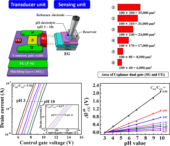
The sensitivity of conventional ion-sensitive field-effect transistors (ISFETs) is limited by the Nernst equation, which is not sufficient for detecting weak biological signals. In this study, we propose a silicon-on-insulator-based coplanar dual-gate (Cop-DG) ISFET pH sensor, which exhibits better performance than the conventional ISFET pH sensor. The Cop-DG ISFETs employ a Cop-DG consisting of a control gate (CG) and a sensing gate (SG) with a common gate oxide and an electrically isolated floating gate (FG). As CG and SG are capacitively coupled to FG, both these gates can efficiently modulate the conductance of the FET channel. The advantage of the proposed sensor is its ability to amplify the sensitivity effectively according to the capacitive coupling ratio between FG and coplanar gates (SG and CG), which is determined by the area of SG and CG. We obtained the pH sensitivity of 304.12 mV/pH, which is significantly larger than that of the conventional ISFET sensor (59.15 mV/pH, at 25 °C). In addition, we measured the hysteresis and drift effects to ensure the stability and reliability of the sensor. Owing to its simple structure, cost-effectiveness, and excellent sensitivity and reliability, we believe that the Cop-DG ISFET sensor provides a promising point-of-care biomedical applications.
Introduction
The portable lab-on-a chip biosensing platforms have made a remarkable progress in recent years.1−4 They enable the collection and processing of biological and chemical signals at the point-of-care (POC). The concept of ion-sensitive field-effect transistors (ISFETs) was proposed by Bergveld in 1970,5 and it is now the typically used FET for fabricating biosensors. Compared to the sensors based on surface plasmon resonance, quartz crystal microbalance, chemiluminescence, and chromatography, ISFETs are considered as the most promising sensors for building lab-on-a-chip platforms because of their compatibility with CMOS technology, which facilitates low cost through mass production while ensuring their portability and robustness.6 This allowed to develop a large-area ISFET-based biosensor array capable of detecting different biomaterials on the chip surface, which is suitable for the POC clinical diagnostics.7−10
Conventional ISFETs are metal–oxide–semiconductor field-effect transistors (MOSFETs) in which the metal gates are removed and the underlying gate oxide is exposed to an electrolyte solution. The theoretical maximum sensitivity of conventional ISFETs is inherently restricted to the Nernst limit (59.15 mV/pH at 25 °C) according to the site binding theory11 and double-layer capacitance of the electrolyte solution.12 The ion-sensing ability entirely depends on the surface potential (ψ) of binding ions and can be expressed as follows13
| 1 |
where k is the Boltzmann constant, T is the absolute temperature, q is the elementary charge, β is the dimensionless parameter that indicates the pH sensitivity of the sensing membrane, Ns is the surface site density, CDL is the double-layer capacitance at the insulator–electrolyte interface, Kb is the basic equilibrium constant, and Ka is the acid equilibrium constant. ψ represents the potential on the sensing membrane surface induced by the pH level of the electrolyte solution.
| 2 |
As ψ decreases according to the pH value, the threshold voltage (Vth) of ISFETs increases. Therefore, it is very important to use a sensing membrane with excellent sensing ability. We fabricated an extended gate (EG) using SnO2 as a sensing membrane with excellent sensing characteristics and stability.14 To overcome the low sensitivity of ISFETs, more advanced sensor architectures and extensive signal postprocessing circuits have been investigated. For example, dual-gate ISFETs have been reported that can amplify the sensitivity using capacitive coupling effects between the upper and lower gate oxide layers of the channel.15 However, to enhance the capacitive coupling effect, a vertical structure dual-gate (V-DG) ISFET sensor requires a thinner top gate oxide or a thicker bottom gate oxide. A thinner top gate oxide causes a gate leakage current. Meanwhile, increasing the bottom gate oxide layer is not efficient in terms of processing time and cost because the buried oxide (BOX) layer thickness must be increased in the fabrication of silicon-on-insulator (SOI) substrates.16−18 Moreover, advanced signal postprocessing circuits require large power consumption and auxiliary external hardware.19 These solutions are not suitable for POC diagnostic platforms. Therefore, in this study, we propose a coplanar dual-gate (Cop-DG) ISFET pH sensor to overcome the drawbacks of the V-DG ISFET pH sensor or advanced signal postprocessing circuits. The Cop-DG ISFETs consists of two coplanar gates: a control gate (CG) and a sensing gate (SG) formed in the same plane of the channel and a floating gate (FG) embedded between the common gate oxide and the shielding oxide layer. Because FG is electrically isolated, the voltages of CG and SG are simultaneously applied to FG. Subsequently, the voltage of FG is transferred to the channel of the silicon thin film. Figure 1 shows a schematic of the transducer unit and the EG sensing unit of the fabricated Cop-DG ISFET pH sensor. The conductance of the FET channel is modulated by the interaction between these gates, and the Cop-DG ISFETs amplify the sensing signal according to the capacitive coupling ratio between capacitances CCG (CG–FG) and CSG (SG–FG). As CCG and CSG possess a common gate oxide of the same thickness, this coupling is mainly determined by the area of each gate. Thus, Cop-DG ISFETs can modulate the capacitive coupling more efficiently than V-DG ISFETs, simplifying the device fabrication process and facilitating their cost effectiveness. The maximum sensitivity of the proposed Cop-DG ISFETs was measured in the DG sensing mode using SG and CG. SG receives the biological signal, while CG sweeps the voltage to measure the drain current (IDS). The threshold voltage of CG shifts according to the potential of SG, that is, the magnitude of the biological signal, causing a change in IDS. The pH sensitivity of Cop-DG ISFETs was defined as the threshold voltage shift of CG (ΔVCGth) according to the pH level. In addition, to realize a cost-effective and disposable biosensor, we have separated the sensing and transducer units using an inexpensive EG, which is the sensing unit, as shown in Figure 1.20 This isolated structure is advantageous because the transducer unit, which is more sophisticated and expensive than the sensing unit, can be used continuously while being completely protected from chemical instability.
Figure 1.
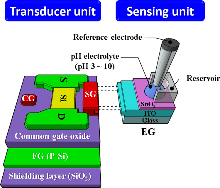
Schematic of the transducer unit and the EG sensing unit of the fabricated Cop-DG ISFET pH sensor.
Results and Discussion
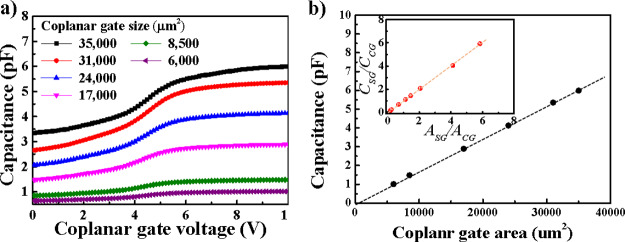
Figure 2a shows the C–V curves measured using MOS capacitors for various sizes of coplanar gates (SG and CG) and FG of the fabricated Cop-DG ISFETs. We measured the C–V curves with a frequency of 200 kHz, a voltage level of 0.03 V, and a delay time of 0.0001 s. The various sizes of the coplanar gates (SG and CG) are 5.99, 5.35, 4.13, 2.89, 1.48, and 1.01 pF for the gate sizes of 100 × 350, 100 × 310, 100 × 240, 100 × 170, 100 × 85, and 100 × 60 μm2, respectively. In the actual sensing operation, the deletion of p-Si does not occur rarely because the FG is floated. The capacitances of the coplanar gates (SG and CG) are 5.97, 5.16, 4.04, 2.89, 1.51, and 1.01 pF for coplanar gate sizes of 100 × 350, 100 × 310, 100 × 240, 100 × 170, 100 × 85, and 100 × 60 μm2, respectively. As shown in Figure 2b, the capacitance of the coplanar gates (SG and CG) is linearly proportional to the gate area. The capacitance of the coplanar gates (SG and CG) increases as the coplanar gate area increases. The inset in Figure 2b shows the relationship between CSG/CCG and ASG/ACG. As expected, CSG/CCG is linearly proportional to ASG/ACG. Therefore, we can control the CSG/CCG, which is related with the amplification factor of Cop-DG ISFFETs by controlling the ASG/ACG.
Figure 2.
(a) C–V curves for various gate sizes and (b) capacitance vs coplanar gate area for the fabricated Cop-DG ISFETs. Inset in (b) shows the relationship between CSG/CCG and ASG/ACG.
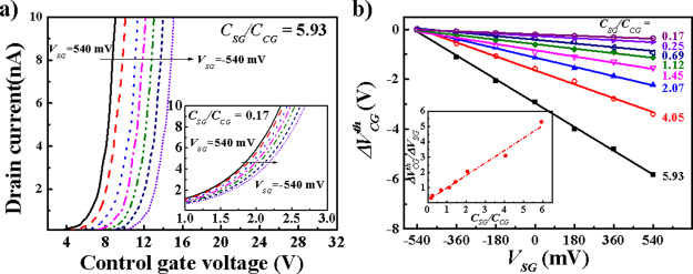
Figure 3a shows the transfer characteristic curve, that is, the drain current (IDS) versus the CG voltage (VCG) for CSG/CCG = 5.93. The inset shows the IDS–VCG curves for CSG/CCG = 0.17. It is evident that as VSG varies from 540 to −540 mV with an interval of 180 mV, VCGth shifts by the capacitance ratio of CSG/CCG. We calculate the VCG using a transconductance extrapolation method in the linear region (GMLE). This method suggests that VCGth corresponds to the x-axis intercept of the linear extrapolation of the gm-VCG characteristics at its maximum first derivative (slope) point.21 We extracted the coupling ratio of CG and SG from the linear relationship of ΔVCG/ΔVSG, as shown in Figure 3b. The practical coupling ratios (ΔVCGth/ΔVSG) between CG and SG of the fabricated Cop-DG ISFETs are 5.31, 3.10, 2.07, 1.39, 1.02, 0.84, 0.48, and 0.33 for CSG/CCG of 5.93, 4.05, 2.07, 1.45, 1.12, 0.69, 0.25, and 0.17, respectively. The inset shows the relationship between ΔVCG/ΔVSG and CSG/CCG, and it is clear that CSG/CCG is almost linearly proportional to ΔVCGth/ΔVSG.
Figure 3.
(a) Transfer characteristic (IDS–VCG) curves of the fabricated Cop-DG ISFETs, where the VSG changes from 540 to −540 mV with an interval of 180 mV for CSG/CCG = 5.93 and 0.17 (inset). (b) Practical coupling ratio (ΔVCGth/ΔVSG) for various CSG/CCG. The inset shows the relationship between ΔVCG/ΔVSG and CSG/CCG.
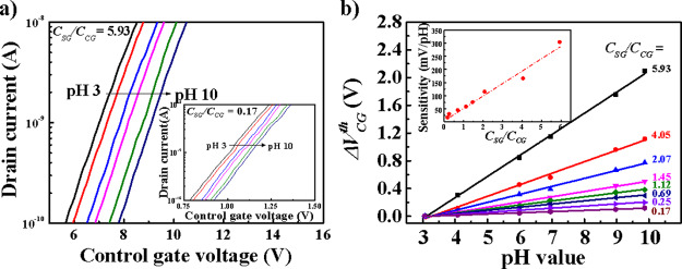
Figure 4 shows the IDS–VCG curves and measured pH sensitivity for various pH electrolyte solutions. Typical IDS–VCG curves with CSG/CCG = 5.93 are shown in Figure 4a, where the curve shifts to the right as the pH increases. The inset shows the IDS–VCG curves for CSG/CCG = 0.17. It is evident that the shift in the transfer characteristic curve for CSG/CCG = 0.17 is much smaller than that for CSG/CCG = 5.93. We can extract the pH sensitivity from the linear relationship of ΔVCGth/ΔpH, as shown in Figure 4b. The sensitivity of the fabricated Cop-DG ISFETs is 304.12, 166.27, 115.36, 75.36, 58.72, 45.67, 30.41, and 17.20 mV/pH for CSG/CCG = 5.93, 4.05, 2.07, 1.45, 1.12, 0.69, 0.25, and 0.17, respectively. It is important to note that we can achieve a much higher sensitivity than 59.15 mV/pH, which is the maximum sensitivity of conventional ISFETs. The main feature of the proposed Cop-DG ISFET sensor is that the capacitive coupling ratio and sensitivity can be adjusted by the capacitance ratio of SG and CG, which improves the pH sensitivity by reducing the ratio of the CG area to the SG area.
Figure 4.
(a) Transfer characteristic (IDS–VCG) curves of the fabricated Cop-DG ISFET sensor for various pH electrolyte solutions, where CSG/CCG = 5.93 and 0.17 (inset). (b) pH sensitivity (ΔVCGth/ΔpH) measured for various CSG/CCG. The inset shows the relationship between pH sensitivity and CSG/CCG.
Furthermore, we compared the coupling ratio between CG and SG (ΔVCGth/ΔVSG) and the amplification of pH sensitivity, as shown in the Supporting Information. In the proposed Cop-DG ISFET sensor, the coupling ratio is important because it determines the amplification of pH sensitivity, which is defined as the amplification factor. The reference sensitivity for obtaining the amplification factor corresponds to a sensor with CSG/CCG = 1, and we extracted a reference sensitivity of 56.98 mV/pH from the inset of Figure 4b. In addition, we simulated the amplification factor for the measured pH sensitivity using a Silvaco TCAD Atlas simulator, which is in excellent agreement with the experimental results. Table 1 summarizes the parameters that govern the amplification factor for the fabricated Cop-DG ISFET pH sensor.
Table 1. Parameters Governing the Amplification Factor in the Fabricated Cop-DG ISFET pH Sensor.
| capacitance ratio (CSG/CCG) | coupling ratio (ΔVCGth/ΔVSG) | pH sensitivity (mV/pH) | amplification factor of pH sensitivity |
|---|---|---|---|
| 5.93 | 5.31 | 304.12 | 5.34 |
| 4.05 | 3.1 | 166.27 | 2.92 |
| 2.07 | 2.07 | 115.36 | 2.02 |
| 1.45 | 1.39 | 75.36 | 1.32 |
| 1.12 | 1.02 | 58.72 | 1.03 |
| 0.69 | 0.84 | 45.67 | 0.8 |
| 0.24 | 0.48 | 30.41 | 0.53 |
| 0.17 | 0.33 | 17.20 | 0.3 |
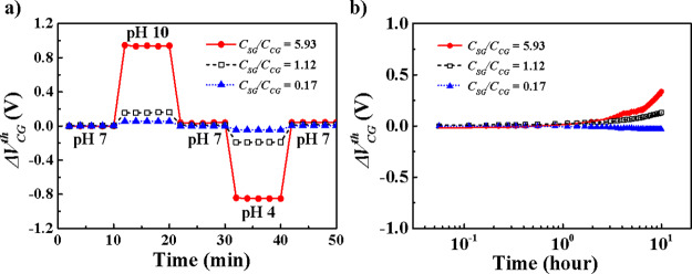
For efficient biosensing platforms, stability and reliability are also important in addition to sensitivity. To evaluate the long-term stability and reliability of the Cop-DG ISFET sensor in the pH electrolyte solution, we measured the hysteresis width and the drift rate, which are shown in Figure 5. In hysteresis and sensitivity measurements, EG was rinsed three times using de-ionized water. Besides, EG was replaced with a new one for every hysteresis loop and every drift measurement. As the sensing membrane reacts slowly with ions (H+ or OH–) in the pH electrolyte solution, the micropotential on the surface of the sensing membrane is changed, which causes hysteresis.22 We measured the hysteresis of the Cop-DG ISFET sensor in the pH loop of pH 7 → pH 10 → pH 7 → pH 4 → pH 7, which is shown in Figure 5a for three cases: CSG/CCG = 5.93, 1.12, and 0.17.
Figure 5.
Evaluation of stability and reliability for the fabricated Cop-DG ISFET sensor: (a) Hysteresis width and (b) drift rate for CSG/CCG = 5.93, 1.12, and 0.17.
The hysteresis width is defined as the voltage difference ΔVCGth between the initial pH 7 electrolyte solution and the final pH 7 electrolyte solution in the pH loop. The hysteresis widths corresponding to CSG/CCG = 5.93, 4.05, 2.07, 1.45, 1.12, 0.69, 0.24, and 0.17 are 41.40, 24.24, 18.40, 15.60, 13.80, 11.71, 8.31, and 4.83 mV, respectively. As CSG/CCG increases, the hysteresis seems to increase. However, the hysteresis for sensitivity, that is, the increase in hysteresis with respect to the increase in sensitivity, is relatively small, as shown in Table 2. In addition, the drift effect causes a voltage shift ΔVCG because of the change in the amount of micropotential as the ions (H+ or OH–) in the pH electrolyte solution penetrate into the sensing membrane for a long time.23 We measured the drift of Cop-DG ISFET sensors for a drift condition (pH 7 electrolyte solution for 10 h), as shown in Figure 5b. The drift rate is defined as ΔVCGth per hour in the drift condition. The drift rate for CSG/CCG = 5.93, 4.05, 2.07, 1.45, 1.12, 0.69, 0.24, and 0.17 is 32.04, 22.55, 16.60, 13.21, 12.11, 9.84, 7.50, and 4.75 mV/h, respectively. Similar to hysteresis, the drift rate seems to increase with the increase of CSG/CCG. However, the drift for sensitivity, that is, the increase in the drift rate with respect to the increased sensitivity, is relatively reduced, as shown in Table 2. These results demonstrate the efficacy of the proposed Cop-DG ISFET sensor, that is, the increase in sensitivity is greater than the increase in hysteresis and drift, and the sensor exhibits excellent reliability and stability. The reason for the relatively good drift for sensitivity and hysteresis for sensitivity is that the micropotential change on the surface because of instability of the sensing membrane, when applied to the CSG, becomes relatively small as the CSG becomes larger than CCG, as shown in eq 3, although the capacitive coupling effect amplifies the noise as well as the signal.
| 3 |
Table 2. Parameters Governing the Stability and Reliability of the Fabricated Cop-DG ISFET pH Sensor.
| capacitance ratio (CSG/CCG) | hysteresis width (mV) | drift rate (mV/h) | hysteresis for sensitivity (%) | drift for sensitivity (%) |
|---|---|---|---|---|
| 5.93 | 41.40 | 32.04 | 13.61 | 10.53 |
| 4.05 | 24.24 | 22.55 | 14.58 | 13.56 |
| 2.07 | 18.40 | 16.60 | 15.95 | 14.39 |
| 1.45 | 15.60 | 13.21 | 20.70 | 17.53 |
| 1.12 | 13.80 | 12.11 | 23.50 | 20.62 |
| 0.69 | 11.71 | 9.84 | 25.64 | 21.55 |
| 0.24 | 8.31 | 7.50 | 27.33 | 24.66 |
| 0.17 | 4.83 | 4.75 | 28.08 | 27.62 |
Conclusions
In this study, we have proposed a SOI-based Cop-DG ISFET pH sensor to overcome the inferior performance of the conventional ISFET pH sensor in detecting weak signals. The fabricated Cop-DG ISFETs employ a dual-gate consisting of CG and SG on the same plane of the Si channel, and FG is electrically isolated with a common gate oxide layer. We designed CG and SG to be capacitively coupled to FG so that both the gates can be used to modulate the conductance of the FET channel. As the amplification ratio of Cop-DG ISFETs is determined by the capacitive coupling ratio, the pH sensitivity can be adjusted by the capacitance ratio of CG to SG. Using this unique feature, we enhanced the pH sensitivity significantly by reducing the ratio of the CG area to the SG area. The sensitivity of the fabricated Cop-DG ISFET pH sensor was measured as 304.12 mV/pH, which is impossible to attain using the conventional single gate ISFET pH sensor with a Nernst limit of 59.15 mV/pH at 25 °C. Although the hysteresis and the drift rate increased simultaneously as the coupling ratio increased, their increase was relatively minor compared to the improvement in the sensitivity. This confirms that the Cop-DG ISFET sensor is effective in terms of sensitivity as well as reliability and stability. Therefore, we believe that the proposed SOI-based Cop-DG ISFET pH sensor provides a promising POC platform for biomedical applications.
Experimental Section
Fabrication Procedure of Cop-DG ISFETs and EG
We fabricated a high-performance Cop-DG ISFET pH sensor using a SOI wafer and a glass substrate. For the transducer unit, Cop-DG ISFETs were fabricated using a p-type (100) SOI wafer with a 20 nm thick top Si layer and a 200 nm thick BOX layer. The BOX layer serves as a common gate oxide for CG and SG. The BOX layer serves as a common gate oxide for CG and SG. In addition, by depositing a 300 nm thick SiO2 layer on the backside of the SOI wafers, the p+ (100) Si substrate of 0.001 Ω·cm under the BOX was electrically isolated and served as an FG. By using an SOI substrate, the proposed FET transducer does not require a well formation process for electrical isolation, which allows for a tighter layout and a simpler manufacturing process. Moreover, it has many advantages, such as leakage current and noise reduction from the body, a steep subthreshold slope, and improved short channel effect immunity.24,25 The active regions were defined with a 10 μm width and a 2 μm length by photolithography and etching processes. The defined thin-film active region can control the depletion region during the sensing operation. However, in the case of a bulk silicon substrate, it is not easy to control the depletion region.26 After the definition of the channel, the source/drain (S/D) regions were heavily doped by ion implantation, followed by rapid thermal annealing at 950 °C for 30 s to activate the implanted phosphorus ions. The coplanar gates (SG and CG) were simultaneously formed by depositing an Al film with a thickness of 150 nm using an electron beam evaporator. For various gate capacitances, the coplanar gates (SG and CG) were designed with sizes of 100 × 350, 100 × 310, 100 × 240, 100 × 170, 100 × 85, and 100 × 60 μm2. The microscopic image of a transducer unit is provided in the Supporting Information. It can play the role of both CG and SG, of which two gate combinations of different sizes were selected for various ratios of capacitive coupling and operated as CG or SG. Finally, forming gas annealing was performed at 400 °C for 30 min in a H2/N2 (5/95%, 50 sccm) ambient. Meanwhile, the EG for the sensing unit was prepared using a glass substrate by sequentially depositing a 300 nm thick indium tin oxide electrode and a 50 nm thick SnO2 sensing membrane on a glass substrate and then immobilizing the 0.6 cm inner diameter polydimethylsiloxane reservoir. The camera image of EG and the simplified cross-sectional schematic diagram of EG are described in the Supporting Information.
Measurements
As shown in the Supporting Information, the capacitance–voltage (C–V) curves were measured using a precision LCR meter (Agilent 4284A) to evaluate the capacitance of various sized gate electrodes. The capacitive coupling ratio was then obtained from the transfer characteristics measured using a precision semiconductor parameter analyzer (Agilent 4156B), as shown in the Supporting Information. The pH sensitivity of the sensor for various electrolytes was measured by connecting an EG sensing unit to the transducer unit, as shown in the Supporting Information, using an Ag/AgCl reference electrode (Horiba 2080A-06T and internal solution: KCl and AgCl) and a precision semiconductor parameter analyzer (Agilent 4156B). The stability and reliability of the pH sensors were evaluated by measuring the hysteresis and drift effects. Hysteresis was assessed by subjecting the sensor to a pH loop of 7 → 10 → 7 → 4 → 7, and the drift rate was obtained by long-term monitoring at pH 7. To avoid the effect of external parameters such as background light and noise, all the measurements were conducted in a dark box. In addition, we used the Silvaco Atlas TCAD tool to estimate the electric field between SG, CG, and FG; capacitive coupling ratios; and amplification factors.
Electrochemical Model
Cop-DG ISFETs employ a Cop-DG (SG and CG) capacitively coupled to FG via a common gate oxide (BOX) layer. A simplified cross-sectional schematic diagram of the sensor is shown in Figure 6a. The electrolyte solution is modeled with the Gouy–Chapman–Stern model.27 The condensed Stern and diffuse layers are represented by their equivalent capacitances CStern and CGouy, respectively. Cop-DG ISFETs are modeled as an n-channel MOSFET with three gates:28,29 CG, SG, and FG. The channel oxide (i.e., common gate oxide) capacitance is represented by COX. The capacitances between CG–FG and SG–FG are CCG and CSG, respectively. VCG is the voltage sweep applied to CG, VREF is the ground potential assigned to the reference electrode, and VSG is given by the surface potential ψ at the sensing film. Furthermore, as shown in Figure 6b, the voltage applied to the FG (VFG) node is defined as the weighted sum of input voltages (Vi), which consist of VSG and VCG. Meanwhile, the input capacitance (Ci) is composed of COX, CSG and CCG. Consequently, Cop-DG ISFETs operate according to the capacitively coupled nodes of input voltage. The net charge at the FG (QFG) is expressed as follows30
| 4 |
where VFG, Vi, and Ci are the voltage applied to the FG, input gate potential, and input capacitance, respectively. Although the actual Cop-DG ISFETs contain many parasitic capacitances, they have been ignored to simplify the modeling of the pH sensor. The simplified change in VFG from eq 4 can be given by eq 5.
| 5 |
where CTOT = CCG + CSG + COX. CCG and CSG are defined in terms of the respective gate area. The variation of VFG depends on the change in VCG and VSG. As CG and SG are capacitively coupled to FG, both of them can modulate the conductance of the sensor channel. If the VSG corresponding to the pH concentration changes the VFG, the result affects the sweeping VCG, leading to a change in the threshold voltage of CG (VCGth). Then, the threshold voltage shift of CG (ΔVCG) with respect to the potential change of SG (ΔVSG) is described as follows
| 6 |
where VCGth is the threshold voltage of FG. This implies that VCG shifts by the ratio of capacitances of SG and CG (CSG/CCG) depending on ψ (i.e., the pH level of the electrolyte). CSG/CCG is determined by the ratio of the Cop-DG area (ASG/ACG).
Figure 6.
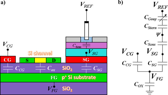
(a) Simplified cross-sectional schematic diagram of Cop-DG ISFETs. In particular, the Si channel was drawn by rotating 90°. (b) Equivalent circuit for modeling.
Acknowledgments
This research was supported by a research grant from Kwangwoon University in 2020 and the Basic Science Research Program through the National Research Foundation of Korea (NRF) funded by the Science and Technology (no. 2016R1A2B4008754) and Business for Cooperative R&D between Industry, Academy, and Research Institute funded by the Korea Small and Medium Business Administration in 2018. The work reported in this paper was conducted during the sabbatical year from the Kwangwoon University in 2020. This research was funded and conducted under (the Competency Development Program for Industry Specialists) of the Korean Ministry of Trade, Industry and Energy (MOTIE), operated by Korea Institute for Advancement of Technology (KIAT). (no. P0002397, HRD program for Industrial Convergence of Wearable Smart Devices)
Supporting Information Available
The Supporting Information is available free of charge at https://pubs.acs.org/doi/10.1021/acsomega.0c00427.
Micrograph of FET transducers and images of the coplanar dual-gates (SG and DG); photograph of the fabricated EG and the cross-sectional schematic of EG on the glass substrate; C–V characteristics of Cop-DG for CG and SG; capacitive coupling ratio between SG and CG; comparison of the amplification factor of pH sensitivity and coupling ratio of the Cop-DG ISFET sensor; development of eqs 5 and 6 from eq 4; extraction method of the threshold voltage (Vth); comparison of Cop-DG ISFETs and V-DG ISFETs; relationship of the drain current (IDS) of the Cop-DG ISFET sensor with the CG voltage (VCG); and IDS–T curve measurements (PDF)
Author Contributions
The manuscript was written through the contributions of all authors. All authors have given approval to the final version of the manuscript.
The authors declare no competing financial interest.
Supplementary Material
References
- Sun H.; Tian F.; Liang Z.; Sun T.; Yu B.; Yang S. X.; He Q.; Zhang L.; Liu X. Sensor array optimization of electronic nose for detection of bacteria in wound infection. IEEE Trans. Ind. Electron. 2017, 64, 7350–7358. 10.1109/tie.2017.2694353. [DOI] [Google Scholar]
- Lee H.; Choi T. K.; Lee Y. B.; Cho H. R.; Ghaffari R.; Wang L.; Choi H. J.; Chung T. D.; Lu N.; Hyeon T.; Choi S. H.; Kim D.-H. A graphene-based electrochemical device with thermoresponsive microneedles for diabetes monitoring and therapy. Nat. Nanotechnol. 2016, 11, 566. 10.1038/nnano.2016.38. [DOI] [PubMed] [Google Scholar]
- Imani S.; Mercier P. P.; Bandodkar A. J.; Kim J.; Wang J.. Wearable chemical sensors: Opportunities and challenges. 2016 IEEE International Symposium on Circuits and Systems (ISCAS); IEEE, 2016; pp 1122–1125.
- Rose D. P.; Ratterman M. E.; Griffin D. K.; Hou L.; Kelley-Loughnane N.; Naik R. R.; Hagen J. A.; Papautsky I.; Heikenfeld J. C. Adhesive RFID sensor patch for monitoring of sweat electrolytes. IEEE Trans. Biomed. Eng. 2015, 62, 1457–1465. 10.1109/tbme.2014.2369991. [DOI] [PubMed] [Google Scholar]
- Bergveld P. Development, operation, and application of the ion-sensitive field-effect transistor as a tool for electrophysiology. IEEE Trans. Biomed. Eng. 1972, BME-19, 342–351. 10.1109/tbme.1972.324137. [DOI] [PubMed] [Google Scholar]
- Bausells J.; Carrabina J.; Errachid A.; Merlos A. Ion-sensitive field-effect transistors fabricated in a commercial CMOS technology. Sens. Actuators, B 1999, 57, 56–62. 10.1016/s0925-4005(99)00135-5. [DOI] [Google Scholar]
- Zhang J. R.; Rupakula M.; Bellando F.; Cordero E. G.; Longo J.; Wildhaber F.; Herment G.; Guérin H.; Ionescu A. M.. All CMOS Integrated 3D-Extended Metal Gate ISFETs for pH and Multi-Ion (Na+, K+, Ca 2+) sensing. IEEE International Electron Devices Meeting (IEDM); IEEE, 2018; pp 12–21.
- Douthwaite M.; Koutsos E.; Yates D. C.; Mitcheson P. D.; Georgiou P. A thermally powered ISFET array for on-body pH measurement. IEEE Trans. Biomed. Circ. Syst. 2017, 11, 1324–1334. 10.1109/tbcas.2017.2727219. [DOI] [PubMed] [Google Scholar]
- Rosenstein J. K.; Lemay S. G.; Shepard K. L. Single-molecule bioelectronics. Wiley Interdiscip. Rev.: Nanomed. Nanobiotechnol. 2015, 7, 475–493. 10.1002/wnan.1323. [DOI] [PMC free article] [PubMed] [Google Scholar]
- Ma D.; Rodriguez-Manzano J.; de Mateo Lopez S.; Kalofonou M.; Georgiou P.; Toumazou C. Adapting ISFETs for Epigenetics: An Overview. IEEE Trans. Biomed. Circ. Syst. 2018, 12, 1186–1201. 10.1109/tbcas.2018.2838153. [DOI] [PubMed] [Google Scholar]
- Meixner L. K.; Koch S. Simulation of ISFET operation based on the site-binding model. Sens. Actuators, B 1992, 6, 315–318. 10.1016/0925-4005(92)80077-b. [DOI] [Google Scholar]
- Bousse L.; De Rooij N. F.; Bergveld P. Operation of chemically sensitive field-effect sensors as a function of the insulator-electrolyte interface. IEEE Trans. Electron Devices 1983, 30, 1263–1270. 10.1109/t-ed.1983.21284. [DOI] [Google Scholar]
- Knopfmacher O.; Tarasov A.; Fu W.; Wipf M.; Niesen B.; Calame M.; Schönenberger C. Nernst limit in dual-gated Si-nanowire FET sensors. Nano Lett. 2010, 10, 2268–2274. 10.1021/nl100892y. [DOI] [PubMed] [Google Scholar]
- Chou J. C.; Wang Y. F. Preparation and study on the drift and hysteresis properties of the tin oxide gate ISFET by the sol–gel method. Sens. Actuators, B 2002, 86, 58–62. 10.1016/s0925-4005(02)00147-8. [DOI] [Google Scholar]
- Jang H.-J.; Bae T.-E.; Cho W.-J. Improved sensing performance of polycrystalline-silicon based dual-gate ion-sensitive field-effect transistors using high-k stacking engineered sensing membrane. Appl. Phys. Lett. 2012, 100, 253703. 10.1063/1.4729762. [DOI] [Google Scholar]
- Lee I.-K.; Lee K. H.; Lee S.; Cho W.-J. Microwave annealing effect for highly reliable biosensor: dual-gate ion-sensitive field-effect transistor using amorphous InGaZnO thin-film transistor. ACS Appl. Mater. Interfaces 2014, 6, 22680–22686. 10.1021/am506805a. [DOI] [PubMed] [Google Scholar]
- Yeo Y.-C.; King T.-J.; Hu C. Direct tunneling leakage current and scalability of alternative gate dielectrics. Appl. Phys. Lett. 2002, 81, 2091–2093. 10.1063/1.1506941. [DOI] [Google Scholar]
- Jang H. J.; Cho W. J. Performance enhancement of capacitive-coupling dual-gate ion-sensitive field-effect transistor in ultra-thin-body. Sci. Rep. 2015, 4, 5284. 10.1038/srep05284. [DOI] [PMC free article] [PubMed] [Google Scholar]
- Moser N.; Lande T. S.; Toumazou C.; Georgiou P. ISFETs in CMOS and emergent trends in instrumentation: A review. IEEE Sens. J. 2016, 16, 6496–6514. 10.1109/jsen.2016.2585920. [DOI] [Google Scholar]
- Cho W.-J.; Lim C.-M. Sensing properties of separative paper-based extended-gate ion-sensitive field-effect transistor for cost effective pH sensor applications. Solid State Electron. 2018, 140, 96–99. 10.1016/j.sse.2017.10.025. [DOI] [Google Scholar]
- Ortiz-Conde A.; Sànchez F. J. G.; Liou J. J.; Cerdeira A.; Estrada M.; Yue Y. A review of recent MOSFET threshold voltage extraction methods. Microelectron. Reliab. 2002, 42, 583–596. 10.1016/s0026-2714(02)00027-6. [DOI] [Google Scholar]
- Tsai C.-N.; Chou J.-C.; Sun T.-P.; Hsiung S.-K. Study on the sensing characteristics and hysteresis effect of the tin oxide pH electrode. Sens. Actuators, B 2005, 108, 877–882. 10.1016/j.snb.2004.11.050. [DOI] [Google Scholar]
- Jamasb S.; Collins S.; Smith R. L. A physical model for drift in pH ISFETs. Sens. Actuators, B 1998, 49, 146–155. 10.1016/s0925-4005(98)00040-9. [DOI] [Google Scholar]
- Celler G. K.; Cristoloveanu S. Frontiers of silicon-on-insulator. J. Appl. Phys. 2003, 93, 4955–4978. 10.1063/1.1558223. [DOI] [Google Scholar]
- Sreedhar N.; Andrew M.. SOI Design: Analog, Memory and Digital Techniques, 1st ed.; Sreedhar N., Andrew M., Eds.; Academic Publishers: Newyork, Boston, Dordrecht, London, and Moscow, 2002; pp 1–22. [Google Scholar]
- Jayant K.; Kan E. C.. Floating gate based sensor apparatus and related floating gate based sensor applications. U.S. Patent 10,309,924 B2, 2019.
- Oldham K. B. Gouy–Chapman–Stern model of the double layer at a (metal)/(ionic liquid) interface. J. Electroanal. Chem. 2008, 613, 131–138. 10.1016/j.jelechem.2007.10.017. [DOI] [Google Scholar]
- Kaisti M.; Zhang Q.; Levon K. Compact model and design considerations of an ion-sensitive floating gate FET. Sens. Actuators, B 2017, 241, 321–326. 10.1016/j.snb.2016.10.051. [DOI] [Google Scholar]
- Kaisti M.; Zhang Q.; Prabhu A.; Lehmusvuori A.; Rahman A.; Levon K. An ion-sensitive floating gate FET model: operating principles and electrofluidic gating. IEEE Trans. Electron Devices 2015, 62, 2628–2635. 10.1109/ted.2015.2441878. [DOI] [Google Scholar]
- Shibata T.; Ohmi T. A functional MOS transistor featuring gate-level weighted sum and threshold operations. IEEE Trans. Electron Devices 1992, 39, 1444–1455. 10.1109/16.137325. [DOI] [Google Scholar]
Associated Data
This section collects any data citations, data availability statements, or supplementary materials included in this article.


