Abstract
Mitral valve repair or replacement is important in the treatment of mitral regurgitation. For valve replacement, a transcatheter approach had the possibility of decrease the invasiveness of the procedure while retaining the benefit of replacement over repair. However, fluoroscopy images acquired during the procedure provide no anatomical information regarding the placement of the probe tip once the catheter has entered a cardiac chamber. By using 3D ultrasound and registering the 3D ultrasound images to the fluoroscopy images, a physician can gain a greater understanding of the mitral valve region during transcatheter mitral valve replacement surgery. In this work, we present a graphical user interface which allows the registration of two co-planar X-ray images with 3D ultrasound during mitral valve replacement surgery.
1. INTRODUCTION
One of the most common cardiac valve-related diseases is mitral regurgitation, which leads to increased morbidity in patients due to left ventricle volume overload and elevated diastolic wall stress, among other causes1. Previously, left untreated, mitral regurgitation caused by flail leaflets was observed to cause a 6.3% increase in mortality rate per year2. As the human life expectancy increased, the number of patients suffering from mitral regurgitation has also increased. Therefore, there has been an increased interest in seeking minimally invasive surgical methods for repairing the mitral valve. According to Grigioni et al.3 2008, in severe cases of mitral regurgitation, surgery has shown to increases the chance of patient survival and decreases postoperative cardiac complication3. From previous patient data, it has been observed that surgical mitral valve repair is a highly durable procedure and reduces the likelihood of reoperation by 92.9% after ten years.
Mitral regurgitation is often seen in cases of myocardial infarction, where remodeling of the left ventricle prevents the mitral valve from forming a proper seal4, with a common treatment option being mitral valve replacement5. Transcatheter mitral valve replacement is now a clinical reality. Endoscopic and robotic surgical approaches are becoming progressively favored over sternotomy access by physicians worldwide6. In comparison to full sternotomy, transcatheter surgery of the mitral valve results in reduction of perioperative morbidity and short-term mortality. Patients who have undergone transcatheter mitral valve replacement reported the following benefits: less postoperative discomfort, improved postoperative breathing, and higher postoperative satisfaction. It also increased long term survival rate in patients7. Shehada et al. searched MEDLINE, EMBASE, and the Cochrane Central Register and analyzed seven studies between January 2011 and December 20158. The studies had data from 1148 patients who underwent cardiac surgeries. 49.2% of the patients had transcatheter aortic valve replacement and 50.8% had surgical aortic valve replacement. It was observed that the patients who underwent transcatheter approach had significantly less strokes (3.8 vs 7.9%) and major bleeding (8.3 versus 15.3%) compared to the surgical approach. Additionally, the duration of the transcatheter procedure (48 to 225 versus 145 to 384 minutes) was also significantly less than surgical approach. However, the transcatheter approach lead to patients suffering from severe paravalvular leakages (10.9% versus 0%) and pacemaker implantation (11.3 versus 3.9%) was significantly higher than in the surgical approach. There were no significant difference in terms of acute kidney injury, major adverse cardiac complications, 30 day mortality, and 1 year mortality3. Moreover, Shehada et al. emphasizes that transcatheter aortic valve replacement is a better approach for patients with aortic valve diseases with prior cardiac surgeries. Each of the seven studies considered by Shehada et al. used echocardiogram to check the preoperative and postoperative condition of the heart. In the study conducted by Conte et al., it was suggested that the high incidence of paravalvular leakage was due to the limitations in imaging with echocardiogram9. They suggest a more accurate form of imaging system for the guidance procedure could significantly reduce paravalvular leakage in transcatheter aortic valve replacements.
Transcatheter mitral valve replacement is a difficult procedure, requiring simultaneous imaging and careful manipulation of a catheter based on imaging. Most often, fluoroscopy is used to track the movement of the catheter in the body. However, this does not provide soft tissue contrast and localization in 3D. Ultrasound imaging offers real-time soft tissue imaging of the heart in 3D10. In this work, we incorporate segmentation, point-cloud registration, and target region transformation and display to aid transcatheter mitral valve replacement.
2. METHODS
2.1. Prototype Robotic Catheter
A 3D-printed, steerable robotic catheter is currently being developed for mitral valve replacement surgery. These steerable catheters have the potential to reduce system fabrication time while allowing patient-specific approaches to be developed as needed11, 12. This robotic catheter will have a synthetic valve attached to the tip, which will be guided into place using X-Ray and ultrasound imaging. Segments of the robotic catheter can be seen in Figure 1.
Figure 1:
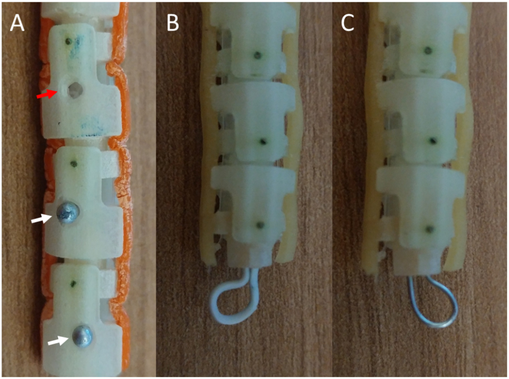
Different approaches to fiducial markers for improved orientation estimation under ultrasound visualization. A) Holes (red arrow) and partially recessed steel pin heads (white arrows) as fiducial markers on a robotic catheter. B) A plastic-coated steel wire loop fiducial attached to the tip of the catheter. C) A similar loop fiducial made using an uncoated steel wire.
2.2. Ultrasound Fiducial
The orientation of the robotic catheter can be difficult to determine under ultrasound, where a rotation about the long axis of the catheter would change which control tendons are needed to induce a bend in the robot tip. In order to aid in the localization, several approaches to fiducials were tested (Figure 1). The first method involved drilling 1.5 mm holes into the robot body (Figure 1A, red arrow). Another approach used partially recessed steel pin heads, with diameters of approximately 1.8 mm, as markers along the body of the robot catheter (Figure 1A, white arrows). The final two methods used a steel wire loop, with and without a plastic coating (Figure 1B and 1C, respectively).
2.3. Guidance Procedure
The guidance procedure is comprised of three parts: (1) binocular catheter imaging using fluoroscopy and soft tissue visualization using ultrasound, (2) catheter point extraction and registration, and (3) target point selection and visualization for catheter guidance.
Point selection on the X-ray images was performed manually. After segmentation, the binary mask is propagated to make a false 3D volume for each catheter. These two binary volumes are overlaid and used to create a point cloud of the catheter in 3D space. Corresponding points from the catheter are then selected by the user on the 3D US volume. A point cloud is then created from the selected points.
Registration of the 3D US and 2D X-ray images was performed using a series of point-cloud affine deformations in a multi-step process. First, the point cloud from the US volume is translated to the point cloud from the X-ray images during a coarse registration. This accounts for the difference in the number of pixels between the imaging modalities and the spatial difference between the different imaging systems. Next, an intermediate ICP registration is applied to adjust rotational differences. For the final step, a fine ICP registration is applied, with a small scaling factor permitted in the registration. The final transformation matrix is preserved and applied to the additional US volumes acquired throughout the surgery.
To demonstrate future feasibility for real-time segmentation, the entire catheter was segmented using a trained U-Net, deployed in MATLAB 2019a. The architecture is shown in Figure 2, with the Dice similarity coefficient13 being used as the loss function. Only two levels were used in the U-Net in order to reduce the segmentation time and enable real-time segmentation, if required. The results of the segmentation will only be analyzed qualitatively.
Figure 2:
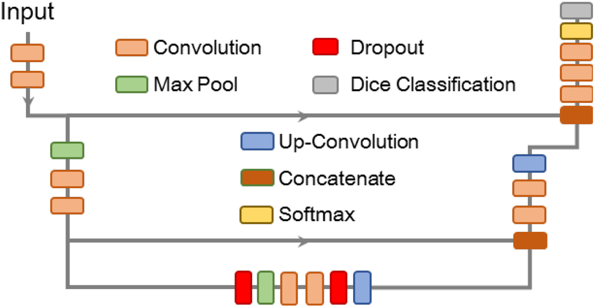
The U-Net architecture used for catheter segmentation for eventual point extraction.
2.4. Graphical User Interface Construction and Interaction
A graphical user interface (GUI) was developed to incorporate user input and assist in data display (Figure 3). The main window shows the data from each imaging modality: two fluoroscopy (or other 2D imaging systems) and a slice from a 3D volume. Alternatively, each imaging feed can be shown by itself in a larger image by selecting the appropriate radio button at the bottom of the GUI. Along the left side of the GUI are buttons a user can select to perform various actions. From the top, they all selection of points on the first 2D image, selection of points on the second 2D image, selection of points on the 3D ultrasound volumes, ICP registration between the 2D and 3D-sourced point clouds, the selection of target points to deform to aid guidance around a particular area of interest, loading of the next images in a time series, and manual point removal of points from the 3D ultrasound point cloud. The drop-down menu below the buttons allows the user to select a different data source for each modality.
Figure 3:
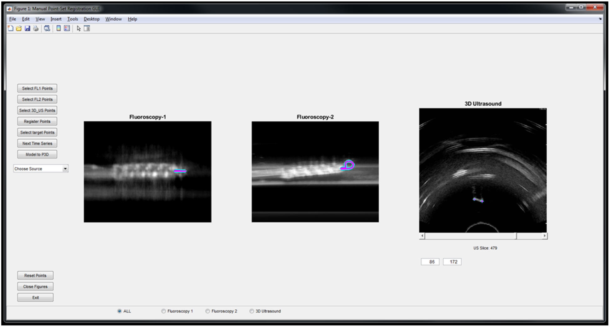
The graphical user interface for incorporating user input during the procedure and displaying the selected catheter points. The display shows points selected on the loop fiducial both simulated fluoroscopy views and a slice from the 3D US volume.
The GUI is also equipped with eight push buttons, a drop-down menu, a slider for the 3D Ultrasound Slices, and controls to set the Window and Level for each imaging modalities. The drop-down menu allows the user to choose the source for each imaging modality. The user can then set the Window and Level for each image by right-clicking the mouse and dragging it around the screen. Right-clicking on the first one third of the GUI will set the Window and Level for the first imaging modality i.e. Fluoroscopy-1, the second one third will set it for Fluoroscopy-2, and the third one third will set it for the 3D Ultrasound. After setting the desired Window and Level for all three imaging modalities, the user can then use the push buttons to select the points in each modality and register them. After the registration is completed the GUI generates two 3D graph showing the registration. The entire workflow is shown on the flowchart in Figure 4.
Figure 4:

User workflow for the imaging aspect of the procedure.
2.5. Registration Evaluation
Registration accuracy was determined using two metrics. The first is the bidirectional Hausdorff distance DH (Equation 1) between the fixed F and moving M point clouds. Here, dH is the Hausdorff distance in one direction between two point clouds.
| (1) |
The other evaluation metric for registration accuracy used is the mean absolute distance (MAD) between each 3DUS-selected point to the nearest pseudo-3D-selected point (Equation 2), where mi is the ith point in the 3DUS point cloud and nM is the total number of points in the 3DUS point cloud.
| (2) |
These two metrics allow quantification of the registration accuracy while still accounting for possible differences in the number of points in each point cloud.
2.6. Datasets
Static imaging conditions were first simulated using 3D ultrasound of a prostate and a CT from the same patient. A synthetic catheter segmentation was added to both the CT and 3D ultrasound, after which two pseudo X-ray images were made by projecting the 3D CT imaging onto two 2D planes.
To test the method with the prototype catheter, a phantom with a smooth curve was constructed using 3% agar solution (Figure 5). The translation stage was used to move the ultrasound probe across the phantom while a video was recorded. This process was repeated ten times, and each time the catheter was moved 12mm forward. In Figure 5A, the top view of the agar phantom without the catheter is shown, whereas Figure 5B shows the same phantom with the catheter inserted.
Figure 5:
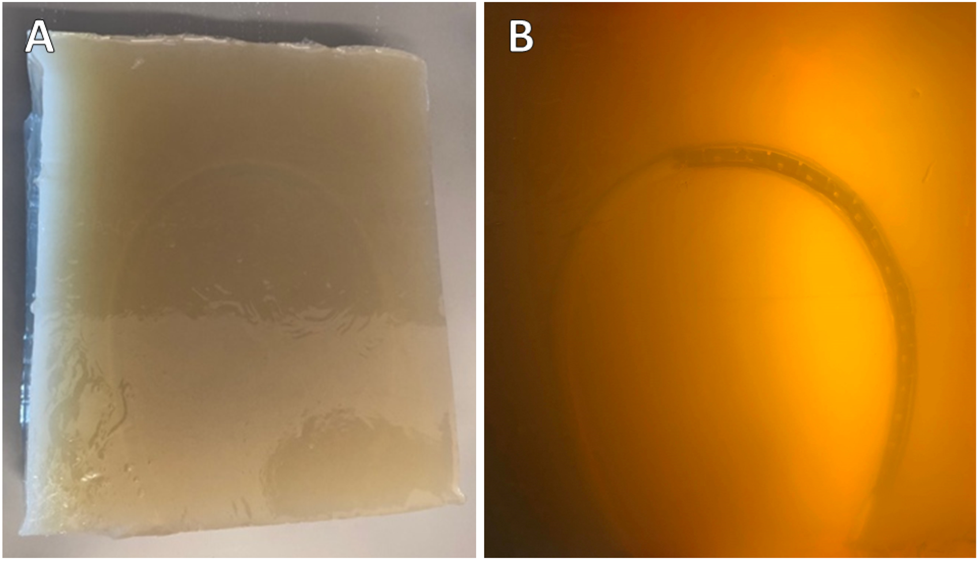
A: Top view of the agar phantom (A) without a catheter and (B) with a catheter inserted.
3. RESULTS
3.1. Automatic Segmentation
An example of catheter segmentation using U-Net on an X-ray image is shown in Figure 6. Part of the catheter is unsegmented, but as this is on the periphery and outside the view of the ultrasound probe, the registration would be unaffected.
Figure 6:
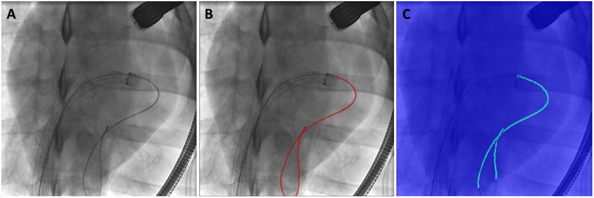
Example of a (A) 2D X-ray, (B) the segmented catheter on the X-ray, and (C) the catheter segmentation from the UNet.
3.2. Fiducial Imaging
Under ultrasound, the drilled hole was most visible when the hole was in-plane with the US frame (Figure 7A, red arrow), and less visible if the hole bisected the ultrasound frame (Figure 7B). The recessed steel pin head fiducial markers were found to be barely visible against the background (white arrows in Figure 7A & B). Due to size restrictions on the width of the catheter, the pin head could not extend further from the catheter. The uncoated steel wire was visible, but faint. The coated wire fiducial performed the best under ultrasound imaging when considering various catheter orientations (Figure 7C), while the uncoated wire loop would vanish when perpendicular to the ultrasound beam direction (Figure 7D). Thus, for the fiducial-based registration, a plastic-coated wire was chosen.
Figure 7:
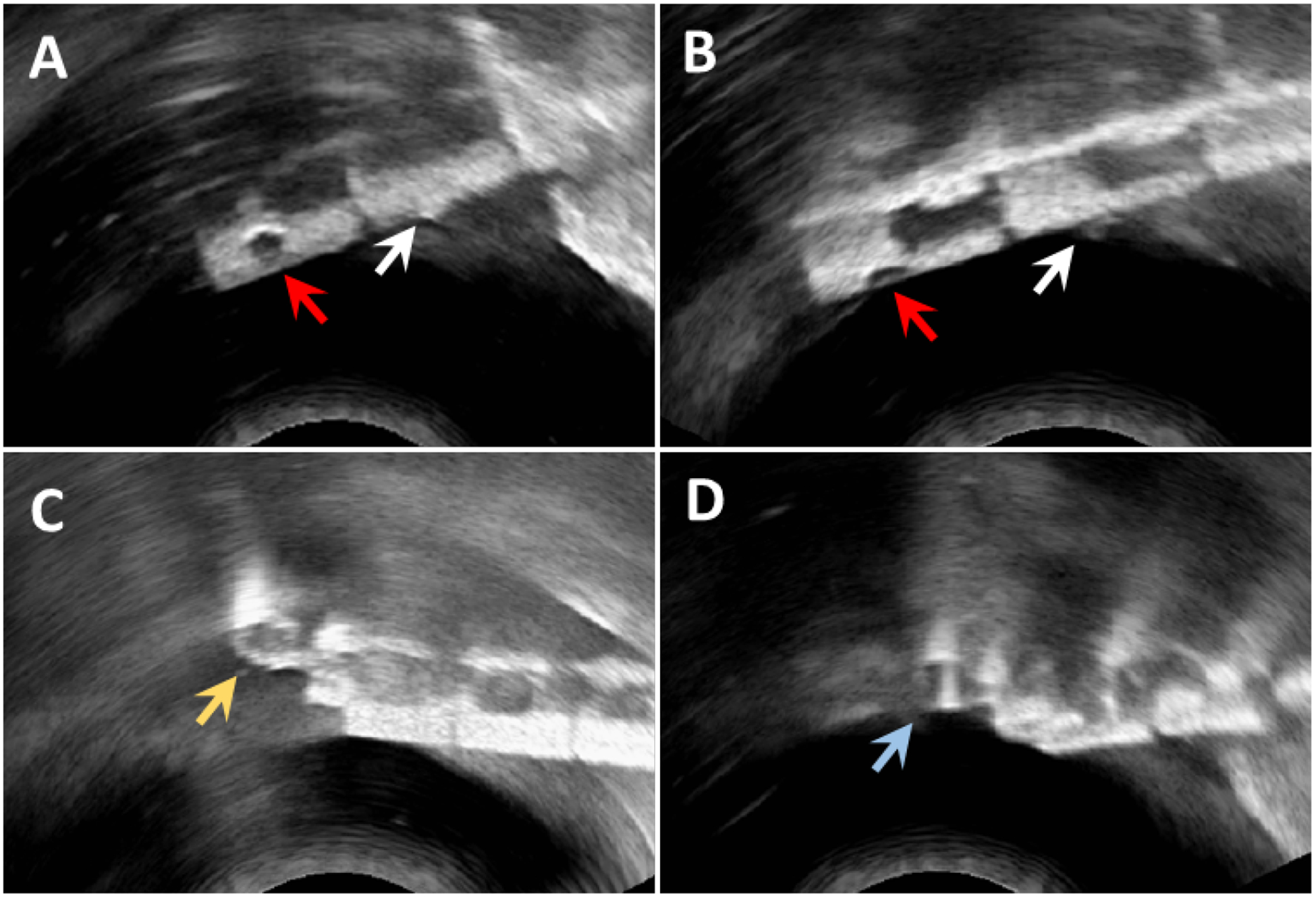
Results of viewing the fiducials under ultrasound. Red arrows in A and B denote the drilled-hole fiducials, while the white arrows indicate the steel pin heads. The partially recessed pin heads are less visible, and both the drilled-hole and pin head fiducial markers exhibit reduced visibility when the marker bisects the imaging plane of the ultrasound probe. The coated (C, yellow arrow) and uncoated (D, blue arrow) wire loop fiducials are visible under any rotation of the catheter.
3.3. Registration
The registration method was first tested using the simulated catheter on the registered 3DUS and CT images of a prostate patient (Figure 8A–B). For this test, the point clouds for registration were generated from segmentations of the entire catheter body on each projected X-ray view and the 3DUS. A mean distance error of 1.28 mm was found, with a Hausdorff distance of 4.34 mm.
Figure 8:
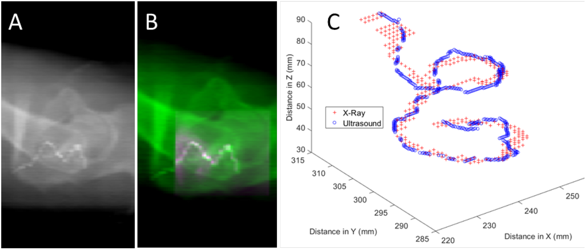
One X-ray view (A) and an example of the registration for the synthetic catheter after the ultrasound volume (pink shading in B) has been overlaid onto the X-ray image (green shading in B). (C) Registered point clouds from the X-ray (red crosses) and ultrasound (blue circles) images.
Results for testing of the robotic catheter with the coated wire fiducial in the water bath are shown in Figure 9 and Table I. Overall, bidirectional Hausdorff distances below 1 mm were achievable, with MAD values below 0.2 mm after the final ICP registration.
Figure 9:

Point clouds after the coarse, intermediate, and fine registration of the coat wire fiducial using points selected from the synthetic 2D images generated from ultrasound and points from a 3D ultrasound volume. Dimensions along each axis are in mm.
Table I.
Results from coated loop fiducial-based registration of the robotic catheter.
| Registration Step | Hausdorff (mm) | MAD (mm) |
|---|---|---|
| Starting Point Clouds | 20.85 | 17.97 |
| After Coarse ICP | 0.92 | 0.22 |
| After Intermediate ICP | 0.84 | 0.20 |
| After Fine ICP | 0.78 | 0.18 |
4. DISCUSSION
Point selection on the 2D images and 3D volume are currently performed manually. However, we can show qualitatively that the catheter itself can be segmented using a simple UNet architecture in X-Ray images. With a proper training dataset of the finalized catheter design and fiducial marker, a robust segmentation model can be made for the X-Ray images for real-time segmentation and thus point generation. The same can be performed for point selection on 3DUS. However, we would expect a deeper neural network would be required, as the 3DUS volumes would contain more noise than the 2D X-Ray images.
Another consideration when using segmentation, as opposed to the current point-selection method, for generating the point clouds is the total number of points selected. In this case, each segmented pixel would correspond to a point in the point cloud. As the total time required for registration of the point clouds scales with the number of points selected, an effort should be made to ensure as sparse a point cloud as possible is used for registration. Careful selection of appropriate fiducials can assist with limiting the number of points required for accurate registration. A large fiducial, while easier to see under ultrasound and X-Ray, would also have more points for registration. This could be mitigated by sparsely sampling the point cloud generated from the segmentation.
In addition to size, the material comprising a fiducial must also be considered. While mostly visibly under ultrasound in Figure 7A and B, a drilled-hole fiducial is unlikely to be clearly visible on X-Ray images. This type of fiducial can also affect the structural integrity of the catheter, especially when several would be required in order to correctly register point clouds between the 2D and 3D images. In contrast, the coated wire would be visible under X-Ray imaging as well as ultrasound. By shaping the wire into a ‘P-shaped’ loop, the long-axis rotation of the catheter can also be found. This knowledge is vital to accurate control of the robotic catheter.
5. CONCLUSION
In this work, we present a method for reconstructing a coarse 3D model of a catheter from two X-ray images and registering the reconstruction with a 3D ultrasound volume. The transformation matrix can then be applied to additional US volumes acquired throughout the procedure. This is vital, as 3D ultrasound enables real-time guidance during mitral valve replacement surgery while also providing soft tissue information.
Future work extends the functionality of the method by incorporating real-time data directly into MATLAB using a frame-grabber connected to the ultrasound system and a magnetic tracker attached to a 2D ultrasound probe, as described by Morgan et al.14. The 2D free-hand ultrasound frames can be combined into a 3D volume in near-real time, allowing the presented method to be used with a larger variety of ultrasound systems.
ACKNOWLEDGMENTS
This research was supported in part by the U.S. National Institutes of Health (NIH) grants (R01CA156775, R01CA204254, R01HL140325, and R21CA231911) and by the Cancer Prevention and Research Institute of Texas (CPRIT) grant RP190588.
REFERENCES
- [1].Grigioni F, Enriquez-Sarano M, Zehr KJ, Bailey KR, and Tajik AJ, “Ischemic mitral regurgitation: long-term outcome and prognostic implications with quantitative Doppler assessment,” Circulation, 103(13), 1759–1764 (2001). [DOI] [PubMed] [Google Scholar]
- [2].Enriquez-Sarano M, “Timing of mitral valve surgery,” Heart, 87(1), 79–85 (2002). [DOI] [PMC free article] [PubMed] [Google Scholar]
- [3].Grigioni F, Tribouilloy C, Avierinos JF, Barbieri A, Ferlito M, Trojette F, Tafanelli L, Branzi A, Szymanski C, Habib G, Modena MG, and Enriquez-Sarano M, “Outcomes in Mitral Regurgitation Due to Flail Leaflets: A Multicenter European Study,” JACC: Cardiovascular Imaging, 1(2), 133–141 (2008). [DOI] [PubMed] [Google Scholar]
- [4].Barzilai B, Gesslr C Jr, Pérez JE, Schaab C, and Jaffe AS, “Significance of Doppler-detected mitral regurgitation in acute myocardial infarction,” The American journal of cardiology, 61(4), 220–223 (1988). [DOI] [PubMed] [Google Scholar]
- [5].Acker MA, Parides MK, Perrault LP, Moskowitz AJ, Gelijns AC, Voisine P, Smith PK, Hung JW, Blackstone EH, Puskas JD, Argenziano M, Gammie JS, Mack M, Ascheim DD, Bagiella E, Moquete EG, Ferguson TB, Horvath KA, Geller NL, Miller MA, Woo YJ, D’Alessandro DA, Ailawadi G, Dagenais F, Gardner TJ, O’Gara PT, Michler RE, and Kron IL, “Mitral-Valve Repair versus Replacement for Severe Ischemic Mitral Regurgitation,” New England Journal of Medicine, 370(1), 23–32 (2013). [DOI] [PMC free article] [PubMed] [Google Scholar]
- [6].van der Merwe J, and Casselman F, “Mitral Valve Replacement-Current and Future Perspectives,” Open Journal of Cardiovascular Surgery, 9, 1179065217719023 (2017). [DOI] [PMC free article] [PubMed] [Google Scholar]
- [7].Lucà F, Van Garsse L, Rao CM, Parise O, La Meir M, Puntrello C, Rubino G, Carella R, Lorusso R, and Gensini GF, “Minimally invasive mitral valve surgery: a systematic review,” Minimally invasive surgery, 2013, (2013). [DOI] [PMC free article] [PubMed] [Google Scholar]
- [8].Shehada S-E, Elhmidi Y, Öztürk Ö, Kasel M, Frangieh AH, Mourad F, Benedik J, El Bahi J, El Gabry M, Thielmann M, Jakob H, and Wendt D, “Transcatheter versus Surgical Aortic Valve Replacement after Previous Cardiac Surgery: A Systematic Review and Meta-Analysis,” Cardiology research and practice, 2018, 4615043–4615043 (2018). [DOI] [PMC free article] [PubMed] [Google Scholar]
- [9].Conte JV, Gleason TG, Resar JR, Adams DH, Deeb GM, Popma JJ, Hughes GC, Zorn GL, and Reardon MJ, “Transcatheter or surgical aortic valve replacement in patients with prior coronary artery bypass grafting,” The Annals of thoracic surgery, 101(1), 72–79 (2016). [DOI] [PubMed] [Google Scholar]
- [10].Jenkins C, Bricknell K, and Marwick TH, “Use of real-time three-dimensional echocardiography to measure left atrial volume: Comparison with other echocardiographic techniques,” Journal of the American Society of Echocardiography, 18(9), 991–997 (2005). [DOI] [PubMed] [Google Scholar]
- [11].Sheng J, Deaton NJ, and Desai JP, “A Large-Deflection FBG Bending Sensor for SMA Bending Modules for Steerable Surgical Robots.” 900–906. [Google Scholar]
- [12].Desai JP, Sheng J, Cheng SS, Wang X, Deaton NJ, and Rahman N, “Toward Patient-Specific 3D-Printed Robotic Systems for Surgical Interventions,” IEEE Transactions on Medical Robotics and Bionics, 1(2), 77–87 (2019). [DOI] [PMC free article] [PubMed] [Google Scholar]
- [13].Dormer J, Qin X, Shen M, Wang S, Zhang X, Jiang R, Wagner MB, and Fei B, “Determining cardiac fiber orientation using FSL and registered ultrasound/DTI volumes,” SPIE Medical Imaging, 979015–979015–7 (2016). [DOI] [PMC free article] [PubMed] [Google Scholar]
- [14].Morgan MR, Broder JS, Dahl JJ, and Herickhoff CD, “Versatile Low-Cost Volumetric 3-D Ultrasound Platform for Existing Clinical 2-D Systems,” IEEE Transactions on Medical Imaging, 37(10), 2248–2256 (2018). [DOI] [PubMed] [Google Scholar]


