Abstract
Multimaterial bioprinting provides a promising strategy to recapitulate complex heterogeneous architectures of native tissues in artificial tissue analogs in a controlled manner. However, most of the existing multimaterial bioprinting techniques relying on multiple printing nozzles and complicate control program make it difficult to flexibly change the material composition during the printing process. Here, we developed a multicomponent bioprinting strategy to produce heterogeneous constructs using a microfluidic printhead with multiple inlets and one outlet. The composition of the printed filaments can be flexibly changed by adjusting volumetric flow rate ratio. Heterogeneous hydrogel constructs were successfully printed to have predefined spatial gradients of inks or microparticles. A rotary microfluidic printhead was used to maintain the heterogeneous morphology of the printed filaments as the printing path direction changed. Multicellular concentric ring constructs with two kinds of cell types distribution in the printed filaments were fabricated by utilizing coaxial microfluidic printhead and rotary collecting substrate, which significantly improves the printing efficiency for multicomponent concentric structures. The presented approach is simple and promising to potentially print multicomponent heterogeneous constructs for the fabrication of artificial multicellular tissues.
Keywords: multicomponent printing, microfluidic printhead, bioprinting, heterogeneous constructs
1. Introduction
Recent achievements in bioprinting have showed significant promise in fabricating artificial tissues to meet the increasing demands for tissue engineering and drug screening[1,2]. The most prevailing bioprinting techniques are based on jetting and extrusion, which have less damage to cells during printing and widely adopted to produce structures mimicking native tissues[3-6]. However, native tissues are extremely complicated in both architectures and cell compositions. Extrusion-based printing with a single printhead cannot meet the increasing demands for complex tissues with multiple cell types. To address this challenge, multimaterial printing strategies are developed by incorporating multiple separated printheads to print several kinds of inks[7-14]. During printing, different inks can be deposited at predefined positions through switching the printheads. However, as types of inks increase, the number of printheads in a printing system increases correspondingly, which brings complexity of design and printing control. The printing efficiency and accuracy might be negatively affected due to the switching of different printhead. In addition, it is almost impossible to continuously change the concentrations of various inks during the printing process.
Microfluidics showed great advantages in manipulating multiple types of material flows by flexibly designing internal microchannel networks, which provide a promising way to achieve multimaterial bioprinting in a relatively simple manner[15-22]. Amir et al. designed a stereolithography-based bioprinting platform which used a microfluidic device to fabricate multicomponent hydrogel constructs. It enabled different bioinks flow into the microfluidic device and cross-link by ultraviolet[23]. Ghorbanian et al. developed a microfluidic direct writer who is capable of alternatively delivering two different alginate gel solutions during the fabrication three-dimensional (3D) hydrogel constructs[24]. Hardin et al. developed a microfluidic printhead for the printing of multiple viscoelastic inks such as polydimethylsiloxane (PDMS) and investigated the interface of two inks during printing[25]. However, the effect of laminar flow within the printhead and proportion of flow rate are neglected, which can change the morphology of the printed heterogeneous filaments and further influence printing controllability.
Here, we developed a multicomponent bioprinting system based on microfluidic printhead with three inlets and one outlet, which enables simultaneous multicomponent extrusion and printing of heterogeneous constructs through only one printhead. During the printing process, different inks were connected to different inlets of the printhead and simultaneously or alternatively extruded through the same outlet. We mainly studied spatially controlled distribution of different inks when altering the proportion of volumetric flow rate of different inlets in printing process. In this way, heterogeneous filaments and constructs can be printed along which diverse materials could be spatiotemporally coded. In addition, a rotating motor was added into printing system for printing heterogeneous filament along different printing directions and a coaxial printhead was developed to improve the cross-linking. It could be a possible way to create macro-microscopic integrative multicomponent constructs mimicking native tissues with multiple cells.
2. Materials and Methods
2.1 Materials
Polydimethylsiloxane (PDMS, Sylgard 184) was obtained from Dow Corning (Midland, MI, USA). Alginate with medium viscosity was purchased from Sigma Aldrich (St. Louis, MO, USA). Calcium chloride powder was bought from Aladdin (Shanghai, China). Agarose powder with low melting temperature (87–89°C) was bought from Biowest (Spain). Green fluorescent particles with a particle size of 10 µm and red fluorescent particles with particle size of 10 µm and 3.2 µm were purchased from Base Line (Tianjin, China). Red/green/blue/yellow pigment was purchased from M and G (China). Alginate solutions with different concentration of 1%, 2%, and 3% (w/v) were prepared by dissolving alginate powder into distilled water or culture medium. About 2% (w/v) agarose solution with 2% (w/v) calcium chloride was prepared by dissolving agarose and calcium chloride powders into distilled water at 100°C. After boiling, agarose solution was poured in a Petri dish and cooled down to form a flat agarose hydrogel with a thickness of 3 mm as the collecting substrate. For cell printing, GFP expressing human umbilical vein endothelial cells (GFP-HUVEC; ATCC, Manassas, VA, USA) and red fluorescent protein embryonic rat cardiomyocytes (H9C2, ATCC, Manassas, VA, USA) were added into 3% alginate solution with a density of 5 × 10⁵ cells mL−1.
2.2 Design and Fabrication of Microfluidic Printhead for Multicomponent Printing
The microfluidic printhead was designed to have three inlets and an outlet as shown in Figure 1A. The width (w1) and height (h1) of the inlet channels are 200 µm. The width (w2) and the height (h2) of the outlet channel are 300 µm and 200 µm, respectively. The length of different channels is l1=5 mm and l2=3 mm, respectively. To fabricate the microfluidic printhead, two PDMS components with semi-channels were created by casting PDMS in the designed molds printed by stereolithography technique. During the cast process, the PDMS components were vacuum treated to remove any bubbles and cured at 65ºC for a minimum of 2 h. Then, they were bonded together after oxygen plasma treatment. Finally, the capillary nozzle was inserted into the cylindrical channel (Figure S1, supporting information). The diameter (d1) and the length (l3) of the nozzle is 200 µm and 12 mm. Figure 1B schematically illustrates components of the microfluidic printhead and the fabricated microfluidic printhead is shown in Figure 1C.
Figure 1.
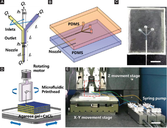
Design of microfluidic printhead for multicomponent bioprinting. (A) Schematic illustration of microfluidic printheads with multiple inlets and an outlet. (B) The assembly of the printhead. (C) Photograph of the fabricated microfluidic printhead. Scale bar=5 mm. (D and E) Schematic and photograph of multicomponent bioprinting platform with microfluidic printhead. Scale bar=5 cm.
2.3 Multicomponent Printing Platform Based on Microfluidic Printhead
The microfluidic printhead was connected with a rotating motor and then mounted on the z moving stage (Xiamen Heidelstar Co., China). Different alginate inks were separately loaded into 1 mL syringes, respectively, and the flow rate was controlled by a syringe pump (TJ-2A, Longer Pump, Baoding, China). Each syringe was connected to different inlets of the printhead through PTEE soft tubes. Agarose hydrogel with calcium ions was placed on the x-y moving stage (Xiamen Heidelstar Co., China) as the collecting substrate (Figure 1D and E). The distance between the nozzle tip and the collecting substrate was fixed at 100 µm. During printing, different inks were pushed into the separate inlets and then extruded out of the printhead through the same nozzle. The proportion of different inks in printed filaments was adjusted by controlling the volumetric flow ratio when the total volume flow rate of all inlets was fixed. A 3D structure with different materials can be printed by precisely stacking the filaments in a layer-by-layer manner.
2.4 Printing of Heterogeneous Filaments
The effect of volumetric flow ratio of different inks on the composition of heterogeneous filament was studied. To code compositions in single printed filament, 3% alginate solutions mixed with green and yellow pigments were used and the flow rate of each inlet was independently controlled by a multichannel syringe pump system. The volumetric flow ratio of two kinds of inks (Q1:Q2) was gradually changed from 3:7 to 7:3 when the total flow rate was 600 µL/h and the speed of moving stage was fixed at 5 mm/s. The line width of different compositions within a single filament was measured, respectively, and the ratio of them was compared with the proportion of flow rate (Q1:Q2). The filaments with three kinds of inks can also be printed by injecting alginate solution with green fluorescent beads through the middle inlet and alginate solution with red fluorescent beads through the left and right inlets. The flow rate of the middle inlet was changed from 200 µL/h to 120 µL/h when the total flow rate of the three inlets was kept at 600 µL/h.
2.5 Printing of Multilayer Heterogeneous Constructs
To demonstrate the ability of microfluidic printhead to print heterogeneous constructs, a heterogeneous grid was printed by altering the proportion of flow rate of different 3% alginate solutions mixed with black and white pigment, respectively. The proportion of flow rate was changes from Qblack: Qwhite=0:1 to Qblack: Qwhite=1:0. In a similar way, 3% alginate solutions mixed with yellow and blue pigment were chosen to fabricate heterogeneous parallel and multilayered grid constructs. When printing the heterogeneous parallel construct, the proportion of flow rates was altered every 10 lines (Qblue:Qyellow=2:1, 1:1, 1:2, and 0:1). During the printing of multilayer heterogeneous construct, the proportion of flow rate was changed every two layers (Qblue:Qyellow=0:1, 1:3, 1:1, 3:1, and 1:0).
To quantitatively analyze and simulate the distribution of different cells in one construct, a coded compositional gradient structure was printed. Green and red fluorescent particles (10 μm) were added into 3% alginate solution and printed by the microfluidic printhead. During printing, the proportion of their flow rate was changed every four layers (Qtotal=600 µL/h, Qred: Qgreen=0:1, 1:2, 1:1, 2:1, and 1:0). The fluorescent profiles of the printed constructs were reconstructed using a confocal laser scanning microscope (OLS4000, Olympus, USA). The number of fluorescent particles in specific layers with different flow rate proportion was quantified by ImageJ software.
2.6 Design of Coaxial Microfluidic Printhead for 3D Multicellular Constructs
To realize the instant cross-linking of the printed filaments for the fabrication of 3D constructs, a coaxial microfluidic printhead was developed. Two kinds of 3% alginate solutions were loaded into two syringes and injected into the printhead at the same flow rate of 300 µL/h. The collecting substrate was fixed on a rotating motor, which was mounted on the x-y moving stage. During the printing process, the collecting substrate was rotating and the heterogeneous filaments were deposited to form a layer of concentric ring structure. Multilayer structures can be obtained by repeating this process in a layer-by-layer manner and simultaneously moving up the nozzle to a certain distance after the completion of each layer printing. The diameter of the ring was determined by eccentric distance between axes of the nozzle and the rotating motor. A multicellular concentric ring was printed using two kinds of inks mixed with HUVECs and H9C2s, respectively.
3. Results and Discussion
3.1 Printing of Heterogeneous Filaments
Unlike laminar flow of two solutions in microfluidic channel, the printing of heterogeneous filaments with microfluidic printhead will subsequently experience deposition and cross-linking processes as shown in Figure 2A. To investigate the effect of these processes on the filament morphology and composition, two kinds of 3% alginate solutions mixed with different color were injected into the microfluidic printhead and extruded from the same outlet. Figure 2B, C, D, E, F illustrates the printed heterogeneous filaments as the flow rate ratio of the two solutions was gradually changed. When the total volumetric flow rate was 600 µL/h, the width of printed filaments was 250±8.89 µm. Since the viscosity of the two solutions was similar, the variation of flow rate ratio had little effect on the filament size. There was a clear boundary of two colored inks in the printed filament. The proportion of two colored materials was approximately equal to that of the flow rate (Figure 2G). This verified that the deposition and cross-linking processes will not affect the printing of heterogeneous filaments. Figure 2H, I, J shows fluorescent images of the filaments printed by injecting different ink from three inlets. As the flow rate of the solution in the middle inlet increased, the number of green fluorescent microbeads in the printed filament increased correspondingly (Figure 2K). Such capability can potentially find various biomedical applications such as accurate patterning of multiple cell types in a single hydrogel filament.
Figure 2.
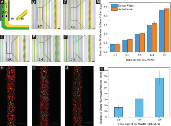
Printing of heterogeneous filaments by changing flow rate ration of different solutions in the microfluidic printhead. (A) Schematic for the deposition of heterogeneous filaments from the microfluidic printhead. (B, C, D, E, F) Microscopic images of heterogeneous filaments printed by changing the flow rate ratio of two solutions. Scale bar=200 µm. (G) Quantification of the composition distribution of two inks in the printed filaments. (H, I, J) Fluorescent images of the heterogeneous filaments printed through the three inlets with different flow rate of middle inlet. Scale bar=200 µm. (K) Quantification of the number of green fluorescent particles at different flow rate of the middle inlet.
We further investigated the influence of solution viscosity on the morphology of heterogeneous filaments by injecting 3% alginate solution (high viscosity) and 1% alginate solution (low viscosity) into the microfluidic printhead simultaneously (Figure 3). It was found that the ink viscosity significantly affected the flow pattern in the microfluidic channel and further changed the spatial distribution of different bioinks in the printed filament. When two kinds of solutions were initially injected into the printhead at the same flow rate, only a small proportion of low-viscous ink flowed into the outlet channel and gradually diffused into the high-viscous side along the flow direction forming a slanted interface (Figure 3C). When the two inks were extruded out from the nozzle, low-viscous ink was found to fully cover the surface of high-viscous inks (Figure 3D). Parallel heterogeneous filaments were not clearly formed even when the flow rate of low-viscous solution gradually increased (Figure S2A, B, C, D). This implied that the presented multicomponent bioprinting is applicable to the inks with similar viscosity. The previous studies indicated that when the fluids have various viscosities, multiphase flow (liquid-liquid two phase) occurs[26-31]. Since most of the bioinks are miscible fluid and surface tension, diffusivity at the interface is an important factor to regulate the flow pattern[32].
Figure 3.
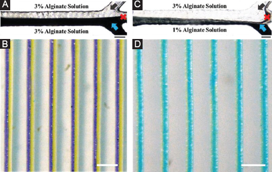
Flow pattern and printed filaments of alginate solution with different viscosities. (A) Injecting 3% alginate solution (high viscosity) simultaneously and (B) printed heterogeneous filaments. (C) Injecting 3% alginate solution and 1% alginate solution and (D) printed filaments. Scale bars are 200 µm and 1 mm.
3.2 Printing of Constructs With Graded Component Composition
Figure 4A demonstrated a 2D filament pattern with gradually changed ink proportion by continuously varying the flow rate ratio of two color-coded inks from 2:1 to 0:1 during printing. A grid pattern with five layers was printed with continuous changed composition as shown in Figure 4B. For each layer, the color of the printed filaments gradually changed from black to white through dynamically adjusting the flow rate of each inlet. Figure 4C schematically illustrates the printing of a multilayered construct with serials of color coding. By sequentially printing two kinds of colored inks with five different flow rate ratios, a vertically gradient structure with 10 layers was finally printed and color of the specific layer was gradually changed from yellow to green and finally to blue as shown in Figure 4D, E, F, G, H.
Figure 4.
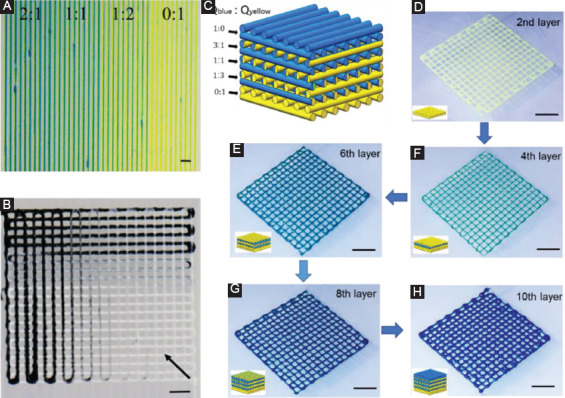
Color-coded heterogeneous constructs. (A and B) Dynamically altering the proportion of different inks during printing. (C) Schematic of color-coded gel structure (10 layers) printed under different proportion of flow rate (Qtotal=600 µL/h, Qblue: Qyellow=0:1, 1:3, 1:1, 3:1, and 1:0) changed per two layers. (D, E, F, G, H) Photograph showing a gradient of colors from yellow to blue during printing. Scale bar=2 mm.
The microfluidic printhead can also be potentially used to fabricate gradient multicellular 3D constructs. As a proof of concept, fluorescent microparticles with a similar size to living cells were used to demonstrate the feasibility. As schematically shown in Figure 5A, the concentration of green fluorescent particles gradually decreased while that of red fluorescent particles increased from the bottom layer to the top layer by dynamically changing the flow rate ratio of two kinds of inks from 1:0 to 0:1 during printing. Figure 5B illustrates the actual spatial distribution of green and red fluorescent particles within the printed grid hydrogel structure, which are accordant with the predefined situation. Figure 5C, D, E, F, G shows the representative distribution of fluorescent particles within different heights ranging from 65 µm to 585 µm with spacing of 130 µm, which related to the layers consisted of different ink proportion. To quantitatively evaluate the spatial distribution of fluorescent particles, the number of green and red fluorescent particles within these specific heights was counted as shown in Figure 5H. It indicates that the ratio of green and red particles was approximately equal to the ratio of flow rate of two kinds of inks within the printhead, which can finally achieve the spatial gradient distribution of the particles as designed. The unique advantage of this method is that it can generate multicellular constructs with spatiotemporal cell positioning in a controllable manner. These kinds of heterogeneous constructs have the potential to meet the demand of biological scaffold involving different kinds of matrix. Together these results demonstrated the unique ability to continuously print heterogeneous construct in both horizontal and altitude direction without interrupt, which could be an efficient and promising method to create constructs with different properties and functions.
Figure 5.
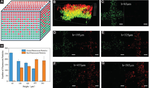
Heterogeneous constructs containing red and green fluorescent microparticles. (A) Schematic of distribution of green/red fluorescent particles in printed constructs. (B) The 3D fluorescence profile of local part of the printed constructs. (C, D, E, F, G) The representative distribution of green/red fluorescence particles at the different heights of the printed construct. Scale bar=100 µm. (H) Quantification of green/red fluorescence particles at different heights in hydrogel structure.
Although the switching process among different printheads is avoided using microfluidic printhead, the transition time to change the proportion of the inks exists during the printing process, which means when changing the flow rates through the syringes, the proportion of inks in the printhead cannot be switched simultaneously. It was found that both flow rate and the concentration influence the transition time (Figure S3 and S4). For inks of alginate solution with concentration ranging from 1% to 3%, all of their transition time decreased with the increase of the flow rate. However, there existed a great drop for the 3% alginate solution, whose transition time was about 430 s at the flow rate of 100 µL/h and about 50 s at the flow rate of 1000 µL/h. For the 1% alginate solution, the transition time was below 50 s at the flow rate of 100 µL/h and 1000 µL/h. The effect of concentration on the transition time might be due to the different viscosity of the alginate solution, which will produce different resistance for ink transition. Thus, the optimum flow rate (600 µL/h) was chose and proportion of flow rate was changed in advance before the designed position. For achieving real-time transition among different inks, integrating small pneumatic valves into microfluidic printhead might be a possible way in the future work.
3.3 Rotating Microfluidic Printhead
As shown in Figure 6A, multicomponent filaments with half-green and half-yellow color can be obtained along the printing direction using microfluidic printhead. However, when the printing direction was changed with 90° to print the next layer of the grid structure, the filaments changed from the left-right multicolor into the top-bottom multicolor. To address this issue, a rotating motor was introduced to this printing system, which enabled the printhead to rotate with the designed angles during the printing process for creating heterogeneous filaments along different directions. Figure 6B shows a grid structure consisting of the filaments with left-right multicolor along the different directions, which is achieved by rotating printhead with 90° as designed during the printing process. Furthermore, a triangular pattern with heterogeneous filaments along three directions and a grid structure coded with three compositions within the filaments was printed through rotating printhead (Figure 6C and D). It could provide a way to create a heterogeneous constructs for bioengineering research, such as controlling of cell distribution and study of the interaction among different types of cells.
Figure 6.
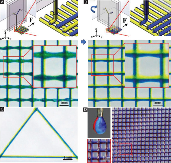
Printing of multicomponent grid structure using rotating microfluidic printhead. (A) Schematic and photograph illustrating printed grid structure without the rotating printhead. (B) Schematic and photograph illustrating printed grid structure with the rotating printhead. (C) Printed triangular pattern with the rotating printhead. (D) Grid structure consists of heterogeneous filaments (red, blue, and purple).
3.4 Printing of Multicellular Constructs Using Coaxial Microfluidic Printheads
To cross-link the printed hydrogel filament during the printing process, a coaxial microfluidic printhead was designed and added into the printing system, as shown in Figure 7A and B. The inner and outer channels were used to deliver the hydrogel ink solution and cross-linking solution independently. The gelation of the inks took place at the tip of the inner nozzle, where these two kinds of solution met. Here, alginate hydrogel solution was printed, which underwent instantaneous gelation when exposed to calcium ions solution. Figure 7C shows the 25-layer heterogeneous hydrogel constructs successfully printed by coaxial printhead.
Figure 7.
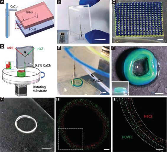
Printing heterogeneous constructs through coaxial microfluidic printheads. (A) Schematic of the coaxial microfluidic printhead. (B) Photograph of the coaxial microfluidic printhead. Scale bar=1 cm. (C) Heterogeneous grid structure (25 layers) printed through using the coaxial microfluidic printhead. Scale bar=2 mm. (D) Schematic of rotating substrate for creating concentric ring “on-the-fly.” (E and F) Fabrication of a heterogeneous concentric ring. Scale bars are 2 mm and 1 mm, respectively. (G) Fabrication of multicellular (H9C2 and HUVEC) concentric rings through coaxial microfluidic printhead. Scale bar=4 mm. (H and I) Fluorescence microscopy image (top view) of multicellular rings. Scale bars are 1 mm and 500 µm, respectively.
To improve efficiency of printing multicomponent concentric ring, a rotary substrate was introduced here (Figure 7D). During the printing process, the printhead did not move while the collecting substrate rotated along printhead as the center. Figure 7E and F shows a heterogeneous concentric ring with the yellow-coded and green-coded alginate hydrogel at the inner and outer side, respectively. As a proof of concept, a multicellular concentric ring was fabricated “on-the-fly” with the diameter of about 8 mm (Figure 7G). Most of the red H9C2s distributed at the inner side, while green HUVECs mainly distributed at the outer side (Figure 7H and I). This printing method shows the promise to fabricate artificial vessels with multilayer in an “on-the-fly” way, especially those with large diameters such as the inferior vena cava whose internal diameter is approximately from 1.7 cm to 2 cm.
4. Conclusion
Here, we demonstrated a multicomponent bioprinting technique based on microfluidic printheads for printing heterogeneous constructs. The microfluidic printhead enables printing of heterogeneous filaments and constructs spatially incorporated with different materials such as particles and cells. Moreover, the constructs consisting of continuous compositional gradient can be fabricated by dynamically altering the flow rates during printing, which is difficult for the multicomponent system with separated printheads to achieve. It was found that the rotating printhead enabled printing the filaments of heterogeneous morphology along different printing directions. The coding of diverse materials on the printed filaments could offer a new way to create functional constructs. Coaxial microfluidic printheads could significantly improve the cross-linking condition. Further exploration of printing multimaterial/cellular concentric rings through the rotating collecting substrate will allow fabrication of artificial vessels efficiently. The proposed method is able to print heterogeneous construct with different components as designed flexibly, which shows promise for a various applications including tissue engineering and soft robots.
Acknowledgments
This work was supported by the National Natural Science Foundation of China (51675412), Shaanxi Key Research and Development Program (2017ZDXM-GY-058), the Youth Innovation Team of Shaanxi Universities and the Fundamental Research Funds for the Central Universities.
References
- 1.Seidi A, Ramalingam M, Elloumi-Hannachi I, et al. Gradient Biomaterials for Soft-to-hard Interface Tissue Engineering. Acta Biomater. 2011;7(4):1441–51. doi: 10.1016/j.actbio.2011.01.011. DOI 10.1016/j.actbio.2011.01.011. [DOI] [PubMed] [Google Scholar]
- 2.Khademhosseini A, Langer R, Borenstein J, et al. Microscale Technologies for Tissue Engineering and Biology. Proc Natl Acad Sci U S A. 2006;103(8):2480–7. doi: 10.1073/pnas.0507681102. [DOI] [PMC free article] [PubMed] [Google Scholar]
- 3.Sakai S, Ueda K, Gantumur E, et al. Drop-on-drop Multimaterial 3D Bioprinting Realized by Peroxidase-mediated Cross-linking. Macromol Rapid Commun. 2018;39(3):1700534. doi: 10.1002/marc.201700534. DOI 10.1002/marc.201700534. [DOI] [PubMed] [Google Scholar]
- 4.Colosi C, Costantini M, Barbetta A, et al. Microfluidic Bioprinting of Heterogeneous 3D Tissue Constructs. Adv Mater. 2016;28(4):677–84. doi: 10.1002/adma.201503310. DOI 10.1002/adma.201503310. [DOI] [PMC free article] [PubMed] [Google Scholar]
- 5.Rutz AL, Hyland KE, Jakus AE, et al. A Multimaterial Bioink Method for 3D Printing Tunable, Cell-compatible Hydrogels. Adv Mater. 2015;27(9):1607–14. doi: 10.1002/adma.201405076. DOI 10.1002/adma.201405076. [DOI] [PMC free article] [PubMed] [Google Scholar]
- 6.Kang HW, Sang JL, Ko IK, et al. A 3D Bioprinting System to Produce Human-scale Tissue Constructs with Structural Integrity. Nat Biotechnol. 2016;34(3):312–9. doi: 10.1038/nbt.3413. DOI 10.1038/nbt.3413. [DOI] [PubMed] [Google Scholar]
- 7.Khalil S, Nam J, Sun W. Multi-nozzle Deposition for Construction of 3D Biopolymer Tissue Scaffolds. Rapid Prototyp J. 2005;11(1):9–17. DOI 10.1108/13552540510573347. [Google Scholar]
- 8.Shim JH, Lee JS, Kim JY, et al. Bioprinting of a Mechanically Enhanced Three-dimensional Dual Cell-laden Construct for Osteochondral Tissue Engineering using a Multi-head Tissue/Organ Building System. J Micromech Microeng. 2012;22(8):85014–24. DOI 10.1088/0960-1317/22/8/085014. [Google Scholar]
- 9.Edward K, Gi Seok J, Young CY, et al. Digitally Tunable Physicochemical Coding of Material Composition and Topography in Continuous Microfibres. Nat Mater. 2011;10(11):877. doi: 10.1038/nmat3108. [DOI] [PubMed] [Google Scholar]
- 10.Pati F, Jang J, Ha DH, et al. Printing Three-dimensional Tissue Analogues with Decellularized Extracellular Matrix Bioink. Nat Commun. 2014;5:3935. doi: 10.1038/ncomms4935. DOI 10.1038/ncomms4935. [DOI] [PMC free article] [PubMed] [Google Scholar]
- 11.Kolesky DB, Truby RL, Sydney GA, et al. 3D Bioprinting of Vascularized, Heterogeneous Cell-laden Tissue Constructs. Adv Mater. 2014;26(19):2966–6. doi: 10.1002/adma.201305506. DOI 10.1002/adma.201305506. [DOI] [PubMed] [Google Scholar]
- 12.Valentine AD, Busbee TA, Boley JW, et al. Hybrid 3D Printing of Soft Electronics. Adv Mater. 2017;29(40):1703817. doi: 10.1002/adma.201703817. DOI 10.1002/adma.201703817. [DOI] [PubMed] [Google Scholar]
- 13.Lind JU, Busbee TA, Valentine AD, et al. Instrumented Cardiac Microphysiological Devices via Multimaterial Three-dimensional Printing. Nat Mater. 2017;16(3):303–8. doi: 10.1038/nmat4782. DOI 10.1038/nmat4782. [DOI] [PMC free article] [PubMed] [Google Scholar]
- 14.Sutanto E, Shigeta K, Kim YK, et al. A Multimaterial Electrohydrodynamic Jet (E-jet) Printing System. J Micromech Microeng. 2012;22(4):45008–18. DOI 10.1088/0960-1317/22/4/045008. [Google Scholar]
- 15.Cheng Y, Zheng F, Lu J, et al. Bioinspired Multicompartmental Microfibers from Microfluidics. Adv Mater. 2014;26(30):5184–90. doi: 10.1002/adma.201400798. DOI 10.1002/adma.201400798. [DOI] [PubMed] [Google Scholar]
- 16.Jun Y, Kang E, Chae S, et al. Microfluidic Spinning of Micro-and Nano-scale Fibers for Tissue Engineering. Lab Chip. 2014;14(13):2145–60. doi: 10.1039/c3lc51414e. DOI 10.1039/c3lc51414e. [DOI] [PubMed] [Google Scholar]
- 17.Kang E, Jeong GS, Choi YY, et al. Digitally Tunable Physicochemical Coding of Material Composition and Topography in Continuous Microfibres. Nat Mater. 2011;10(11):877. doi: 10.1038/nmat3108. DOI 10.1038/nmat3108. [DOI] [PubMed] [Google Scholar]
- 18.Ouyang L, Highley CB, Sun W, et al. A Generalizable Strategy for the 3D Bioprinting of Hydrogels from Nonviscous Photo-crosslinkable Inks. Adv Mater. 2017;29(8):1604983. doi: 10.1002/adma.201604983. DOI 10.1002/adma.201604983. [DOI] [PubMed] [Google Scholar]
- 19.Shi X, Ostrovidov S, Zhao Y, et al. Microfluidic Spinning of Cell-responsive Grooved Microfibers. Adv Funct Mater. 2015;25(15):2250–9. DOI 10.1002/adfm.201404531. [Google Scholar]
- 20.Yu Y, Shang L, Gao W, et al. Microfluidic Lithography of Bioinspired Helical Micromotors. Angew Chem Int Ed. 2017;56(40):12127–31. doi: 10.1002/anie.201705667. DOI 10.1002/anie.201705667. [DOI] [PubMed] [Google Scholar]
- 21.Yu Y, Wei W, Wang Y, et al. Simple Spinning of Heterogeneous Hollow Microfibers on Chip. Adv Mater. 2016;28(31):6649. doi: 10.1002/adma.201601504. DOI 10.1002/adma.201601504. [DOI] [PubMed] [Google Scholar]
- 22.Zhu Y, Wang L, Yin F, et al. A Hollow Fiber System for Simple Generation of Human Brain Organoids. Integr Biol. 2017;9(9):774–81. doi: 10.1039/c7ib00080d. DOI 10.1039/c7ib00080d. [DOI] [PubMed] [Google Scholar]
- 23.Miri AK, Nieto D, Iglesias L, et al. Microfluidics-enabled Multimaterial Maskless Stereolithographic Bioprinting. Adv Mater. 2018;30(27):e1800242. doi: 10.1002/adma.201800242. DOI 10.1002/adma.201800242. [DOI] [PMC free article] [PubMed] [Google Scholar]
- 24.Ghorbanian S, Qasaimeh MA, Akbari M, et al. Microfluidic Direct Writer with Integrated Declogging Mechanism for Fabricating Cell-laden Hydrogel Constructs. Biomed Microdevices. 2014;16(3):387–95. doi: 10.1007/s10544-014-9842-8. DOI 10.1007/s10544-014-9842-8. [DOI] [PubMed] [Google Scholar]
- 25.Hardin JO, Ober TJ, Valentine AD, et al. 3D Printing:Microfluidic Printheads for Multimaterial 3D Printing of Viscoelastic Inks. Adv Mater. 2015;27(21):3279–84. doi: 10.1002/adma.201500222. DOI 10.1002/adma.201570145. [DOI] [PubMed] [Google Scholar]
- 26.Zhao Y, Chen G, Quan Y. Liquid–liquid Two-phase Mass Transfer in the T-junction Microchannels. AIChE J. 2010;53(12):3042–53. DOI 10.1002/aic.11333. [Google Scholar]
- 27.Kakavandi FH, Rahimi M, Jafari O, et al. Liquid–liquid Two-phase Mass Transfer in T-type Micromixers with Different Junctions and Cylindrical Pits. Chem Eng Process Process Intensification. 2016;107:58–67. DOI 10.1016/j.cep.2016.06.011. [Google Scholar]
- 28.Pandey S, Gupta A, Chakrabarti DP, et al. Liquid–liquid Two Phase Flow Through a Horizontal T-junction. Chem Eng Res Des. 2006;84(10):895–904. DOI 10.1205/cherd05061. [Google Scholar]
- 29.Kamholz AE, Weigl BH, Finlayson BA, et al. Quantitative Analysis of Molecular Interaction in a Microfluidic Channel:The T-sensor. Anal Chem. 1999;71(23):5340–7. doi: 10.1021/ac990504j. DOI 10.1021/ac990504j. [DOI] [PubMed] [Google Scholar]
- 30.Ameya J. Numerical Simulation of Immiscible Liquid-liquid Flow in Microchannels using Lattice Boltzmann Method. Sci China Chem. 2011;54(1):244–56. DOI 10.1007/s11426-010-4164-z. [Google Scholar]
- 31.Chakraborty D, Bose N, Sasmal S, et al. Effect of Dispersion on the Diffusion Zone in Two-phase Laminar Flows in Microchannels. Anal Chim Acta. 2012;710(2):88–93. doi: 10.1016/j.aca.2011.10.040. DOI 10.1016/j.aca.2011.10.040. [DOI] [PubMed] [Google Scholar]
- 32.Govindarajan R, Sahu KC. Instabilities in Viscosity-stratified Flow. Annu Rev Fluid Mech. 2014;46(1):331–53. DOI 10.1146/annurev-fluid-010313-141351. [Google Scholar]


