

Abstract
Three-dimensional (3D) printing has been emerging as a new technology for scaffold fabrication to overcome the problems associated with the undesirable microstructure associated with the use of traditional methods. Solvent-based extrusion (SBE) 3D printing is a popular 3D printing method, which enables incorporation of cells during the scaffold printing process. The scaffold can be customized by optimizing the scaffold structure, biomaterial, and cells to mimic the properties of natural tissue. However, several technical challenges prevent SBE 3D printing from translation to clinical use, such as the properties of current biomaterials, the difficulties associated with simultaneous control of multiple biomaterials and cells, and the scaffold-to-scaffold variability of current 3D printed scaffolds. In this review paper, a summary of SBE 3D printing for tissue engineering (TE) is provided. The influences of parameters such as ink biomaterials, ink rheological behavior, cross-linking mechanisms, and printing parameters on scaffold fabrication are considered. The printed scaffold structure, mechanical properties, degradation, and biocompatibility of the scaffolds are summarized. It is believed that a better understanding of the scaffold fabrication process and assessment methods can improve the functionality of SBE-manufactured 3D printed scaffolds.
Keywords: Solvent-based extrusion 3D printing, Ink materials, Ink rheology, Fabrication process parameters, Tissue scaffolds
1 Introduction
3D printing, which is also referred as additive manufacturing, is a process in which a scaffold architecture is initially designed with computer-aided design (CAD) file and subsequently fabricated in a layer-by-layer manner[1]. 3D printing can overcome the limitations of traditional scaffold fabrication methods in terms of scaffold interconnectivity and reproducibility[2-5]. SBE 3D printing is one of the most popular 3D printing techniques. The biomaterials are placed in solvents to create inks; these inks are extruded from nozzles as filaments in layer-by-layer manner to form the scaffold structure[6-10]. The currently utilized ink biomaterials are natural polymers, synthetic polymers, ceramics, and their combinations. SBE 3D printing has been performed with or without cells to create tissue scaffolds for heart valve tissue[11,12], bone tissue[13,14], cartilage tissue[15], blood vessel[16], and skin tissue[17]. Recently, a concept study has described building a scaffold with simultaneous control over multiple biomaterial inks in the desired combination to create biomimetic and functional scaffolds that closely mimic natural tissue[18]. Despite these advances, the lack of feasible inks, particularly bio-composite ink, prevents the clinical use of current SBE 3D printed scaffolds. Scaffolds with appropriate levels of filament uniformity cannot easily be obtained; in addition, there is a poor fidelity between the structures of printed scaffolds and the computer models of these structures[11,19].
In this review paper, the biomaterials used in SBE 3D printing of TE scaffolds are considered. The ink rheology, cross-linking mechanisms, and processing parameters are described. The SBE structure, mechanical properties, biodegradation mechanisms, and biocompatibility, of 3D printed scaffolds, are also discussed. This paper also provides an overview of SBE 3D printing for TE applications and discussed printing-related factors. Hopefully this paper will provide guidance to 3D printing researchers, which facilitates improvements of scaffold design and reproducibility.
2 SBE 3D printing types in TE
The SBE 3D printing technique involves extruding a continuous filament of ink containing biomaterials with or without cells through a nozzle to form 3D woodpile structures in a layer-by-layer manner. The SBE 3D printer includes a three-axis position system, print head, and print platform. The print head is moved to appropriate locations on the build platform by the three-axis position system; inks are extruded from the syringe on the print head in the X, Y, and Z directions[9,10,20]. The printed filament resolution is dependent on the print head nozzle diameter, which can be varied in the range of 10–1000 μm. As shown in Figure 1A-C, SBE 3D printing can be classified as pneumatic driven, piston-driven, and screw-driven based 3D printing. In pneumatic-driven based printing, the inks are forced through the nozzle by control over the compressive air pressure. In the piston and screw-driven based 3D printing, inks are extruded by regulating the motor rotation speed. Among these three classifications of SBE 3D printing approaches, pneumatic-driven based 3D printing is more suitable for printing ink containing cells since the sterilized air can minimize contamination[21,22]. Piston and screw-driven based 3D printing can provide larger deposition forces compared with pneumatic-driven based 3D printing; these approaches are compatible with the printing of relatively high viscosity inks. However, screw-driven based 3D printing is not suitable for the printing of cell-laden inks since the shear stress generated on the blade may cause cell damage[23,24].
Figure 1.
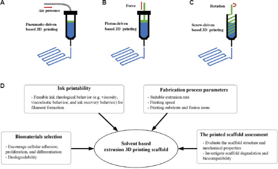
SBE 3D printing types, pneumatic-driven based 3D printing (A); piston-driven based 3D printing (B); screw-driven based 3D printing (C); a schematic showing the factors that influence SBE 3D printing.
There is a wide variability among different tissues and organs in terms of their material composition and mechanical properties[25-27]. As such, functionalization of 3D scaffolds is dependent on material and mechanical parameters and should be tailored according to these parameters as appropriate. For the development of such scaffolds with SBE 3D printing, several factors should be considered (summarized in Figure 1D). These include (a) biomaterial selection for the ink, (b) investigation of the ink rheological behavior, (c) printing process parameters, and (d) assessment of printed scaffold regarding structure, mechanical properties, degradation, and biocompatibility.
3 Ink biomaterials for SBE 3D printing in TE
3.1 Ink materials with cells for SBE 3D printing
Biomaterials used in scaffold fabrication are mixed with solvents to create the liquid feedstock for SBE 3D printing. Table 1 summarizes the use of SBE 3D printing with or without living cells for TE. Biomaterials used with living cells in scaffold fabrication should not only provide an appropriate environment for cell survival but also should be compatible with the printing process. The formulated biomaterial solution is often called a bioink and the processing approach is referred as bioprinting. The most commonly used biomaterials for bioprinting are hydrogels (either natural or synthetic hydrogels); these biomaterials can provide mild aqueous environment to the cells during the printing process. The hydrogels used in SBE 3D printing with cells includes alginate, hyaluronic acid, collagen, gelatin, and silk[12,17,28-30].
Table 1.
The summary of tissue scaffold fabrication using SBE 3D printing
| SBE 3D printing types | Ink materials | Ink rheology properties | Cross-linking mechanisms | Printing process parameters | Scaffold characterization methods | Biological outcomes | Reference | |
|---|---|---|---|---|---|---|---|---|
| Printing with cells | Pneumatic-driven based 3D printing | Alginate, nanocellulose and human chondrocyte mixed in D-mannitol solvent | Ink shear viscosity was measured at the applied shear rate from 0.01 to 1000s−1. Oscillation shear testing was performed to define the linear viscoelastic region. | CaCl2 solution bath | Print speed was at 20 mm/s | The optimal ink was selected by the measurement of the filament width from microscopy images of the printed scaffold. | Human chondrocyte printed with the nanocellulose based ink and the cell viability of 86% after 3D culture for 7 days. | [15] |
| Pneumatic-driven based 3D printing | Hyaluronic acid, gelatin and HAVIC mixed in cell culture medium | Ink shear viscosity was measured at applied shear stress from 1 to 1000 Pa. The elastic modulus of various concentration hydrogels inks was measured. | UV light | No specific mentioned | The printing accuracy was determined by evaluating the measured area and the design. | Increasing gelatin concentration facilitated cell spreading and better maintained HAVIC phenotype. | [12] | |
| Piston-driven based 3D printing | Alginate, gelatin, and hMSCs with different concentration HA mixed in PBS | The viscosity of inks with different HA concentration was at the shear rate from 0.0001 to 100 s−1. Oscillatory shear tests over a temperature ramp from 50 to 10°C to investigate the gel point. | CaCl2 solution bath | Print speed was 2 mm/s and extrusion rate was 0.45 × 10⁻³ mm mm−1 | HA enabled the visualization of the patterns using micro-CT. | hMSCs survived the printing process and showed high cell viability of 85% living cells after three days of subsequent in vitro culture. | [31] | |
| Printing without cells | Pneumatic-driven based 3D printing | PLA and a bioactive CaP glass dissolved in chloroform | CaP glass improved ink viscosity, but no ink rheology test was involved. | Solvent evaporation | The print speed was 3 mm/s | Scaffold pores size and porosity were accessed from the SEM image and micro-CT generated structure to compare with the theoretical values. The compressive modulus of printed scaffolds with different patterns was evaluated by uniaxial compression testing. | The glass particles increased roughness, hydrophilicity, and mechanical property of scaffolds. CaP glass improved MSCs adhesion. | [35] |
| Pneumatic-driven based 3D printing | PCL, HA, and CNT dissolved in dichloromethane | CNT concentration was adjusted to achieve an optimum viscosity between 2.5 and 7 Pa.s. | Solvent evaporation | No specific mentioned | The compressive modulus of printed scaffolds with different CNT concentrations was evaluated by uniaxial compression testing. | HA improved the bioactivity, there was good cell adhesion and spreading at the scaffold surface in vitro. | [36] | |
| Pneumatic-driven based 3D printing | PCL, PLGA, and HA particles mixed in dichloromethane. | The optimal viscosity of 30–35 Pa·s was reached. | Solvent evaporation | The print speed was 15 cm/s, and extrusion rates were as 275 cm3/h | The compressive modulus of printed scaffolds was evaluated by uniaxial compression testing. | Supported cell viability and proliferation and induced osteogenic differentiation of hMSCs in vitro and rapidly integrated with the tissue in vivo. | [13] |
HAVIC: Human aortic valve interstitial cells, PLA: Polylactic acid, MSCs: Mesenchymal stem cells, PCL: Polycaprolactone, HA: Hydroxyapatite, CNT: Carbon nanotubes, PLGA: Poly (lactic-glycolic acid), SBE: Solvent-based extrusion, TE: Tissue engineering, hMSCs: Human mesenchymal stem cells
Duan et al.[12] formulated hydrogel inks with hyaluronic acid and gelatin; they incorporated human aortic valve interstitial cells (HAVICs) within these inks for 3D bioprinting of heart valve conduits. An increase in the gelatin concentration resulted in a lower ink stiffness and a higher viscosity; these parameters facilitated cell spreading and maintenance of a better HAVIC fibroblastic phenotype. They described the dependence of the bioprinting accuracy on the hydrogel concentration; optimization of the ink concentration enable the fabrication of a heart valve shape that matches the original design. Wüst et al.[31] evaluated a combination of alginate and gelatin with various amounts of hydroxyapatite (HA); human mesenchymal stem cells (hMSCs) mixed into the hydrogel/HA inks survived the printing process. The in vitro results show high cell viability, with an 85% cell viability rate after 3 days. The elastic modulus of the alginate-gelatin composite discs increased with the HA concentration. However, the ink became more viscous as the HA concentration was increased; as such, it is difficult to print HA-containing inks. They indicated that control of the tip temperature affected the viscosity of the bioink; increasing the temperature can convert the ink to liquid form, eliminating the clogging issues at the dispenser tips.
Notably, more viscous inks require larger pressures for extrusion from the nozzle; as such, cells in the bioinks are exposed to process-induced forces (i.e., shear stress). The deformation of the cell membrane can occur if the applied force is too high. As such, the shear stress is a key factor that needs to be evaluated during bioprinting. Blaeser et al.[32] developed a fluid dynamics model and performed in vitro experiments to understand shear stress at the nozzle site. The results show that the generated shear stress is affected by the hydrogel ink viscosity, extrusion pressure, and nozzle dimensions. Mouse fibroblasts can exhibit cell viability of 96% if exposed to shear stress of <5 KPa; viability is decreased to 90% and 75% for the shear stress of 5–10 kPa and more than 10 KPa, respectively.
3.2 Ink materials without cells for SBE 3D printing
The cells do not need to be placed within the inks. The printed scaffolds can serve as a support structure to facilitate tissue regeneration on the inherent recovery properties of the tissue. Direct ink writing (DIW) is a common applied method for printing inks that do not contain cells. Ghosh et al.[33] printed tissue scaffolds and microvascular networks using the DIW technique; they fabricated a scaffold with a silk fibroin solution ink; the extruded filament was deposited in a methanol-rich reservoir for crystallization. In vitro studies suggest that the scaffolds supported hMSC adhesion and growth as well as higher chondrogenic differentiation under chondrogenic conditions. Miranda et al.[34] used the DIW technique to produce scaffolds with precise porous features using concentrated TCP and HA inks with suitable viscoelastic properties. The 3D printed ceramic scaffolds have shown promising results for potential use in bone tissue repair; their application is limited due to their brittleness. The incorporation of a polymer material with a ceramic ink is a promising approach to overcome this limitation. The combination of polymer and ceramic components can also mimic the organic and inorganic components of natural bone tissue. Sun et al.[16] developed scaffolds composed of a gradient array of silk/HA, which supported the cocultures of hMSCs and human mammary microvascular endothelial cells (hMMECs). The histology results indicate that the hMSCs and hMMECs form intricate networks of extracellular matrix within the 3D scaffolds.
Some synthetic polymers are not water-soluble and must be mixed with organic solvents to form solutions; these polymers can often provide better mechanical strength than natural polymers. Considering the toxicity of many organic solvents, cells may not be incorporated within synthetic polymer-laden inks. Several synthetic polymers have been used in SBE 3D printing, including polycaprolactone (PCL), polylactic acid (PLA), poly (lactic-glycolic acid) (PLGA), and their copolymers. Serra et al.[35] used PCL and bioactive CaP glass to fabricate 3D scaffolds with orthogonal and displaced double-layer patterns. Their results indicate that scaffolds containing CaP glass particles exhibited increased roughness and hydrophilicity. The preliminary cell response of these materials was studied with MSCs; this study revealed that CaP glass improved cell adhesion. Gonçalves et al.[36] fabricated scaffolds out of composites containing PCL, nano-HA, and carbon nanotubes (CNT). The CNT improved the mechanical behavior of the scaffolds. The in vitro results showed that HA improved bioactivity; good cell adhesion and spreading were noted on the scaffold surface. Although the use of SBE 3D printing to create polymer/ceramic composites is promising for TE applications, only a few studies to this point have investigated the ink printability and processing parameters. Additional studies should be performed to understand optimization of the ink rheology, processing parameters, and cross-linking mechanisms for fabrication of SBE scaffolds.
3.3 Ink rheological behavior in SBE 3D printing
The biomaterial ink solution should have appropriate rheology since the printed structure is prone to collapse if the viscosity of the solution is low. Inks with the non-Newtonian flow and shear thinning behavior are preferred. In shear thinning, high shear rate causes the viscosity of the material solutions to decrease so that it easily flows through the needle. The cells within the ink can influence ink rheology; they can be seen as “non-soluble” microparticles suspended in the solution. Ning et al.[37] investigated the influence of various types of cells and cell density on the viscosity of alginate ink. The results reveal that the viscosity of pure alginate ink was higher than those of inks containing three types of cells. As the cell density in the alginate inks is increased, a reduction in viscosity can be obtained. The results suggest that cells containing cytoplasm can be treated as a fluid with low viscosity; as such, the interactions among cells likely act as lubricants and reduce the viscosity[38]. Dávila and d’Ávila[39] formulated laponite/alginate inks without cells and analyzed the ink rheology in terms of viscosity, viscoelasticity behavior, and ink recovery behavior. As the laponite concentration increased from 0 to 6 wt%, an increase in viscosity was noted at the same shear rate (Figure 2A). Higher laponite concentrations causes strong shear-thinning behaviors. Understanding the viscoelastic behavior of the ink through evaluation of storage and loss modulus values can determine if the material behaves more like a “viscous flow” or “elastic gel.” Figure 2B shows the oscillation shear test results of laponite/alginate inks; by increasing the concentration of laponite particles, the gap between storage modulus and loss modulus is increased. In addition, the ink recovery behavior was also investigated to mimic the ink extrusion process from the nozzle. Figure 2C shows the results of viscosity recovery studies. It was observed that the ink viscosity recovered almost instantaneously when a high shear load was removed; this result is associated with elastic energy stored by the alginate chains. As shown in Figure 2D, filament formation with several concentrations of laponite was evaluated; filaments were formed at laponite concentrations greater than 5 wt%. The ink solution with higher viscosity is relatively more difficult to flow or spread; this phenomenon can serve to maintain the printed filament shape.
Figure 2.
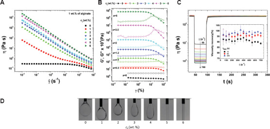
The relationship between viscosity (η) and shear rate (γ̇) for the inks with 1 wt% alginate and a laponite concentration (cL) between 0 and 6 wt% (A); storage modulus (G’) (elastic modulus) and loss modulus (G’’) (viscous modulus) as a function of strain (γ) (B); viscosity as a function of the time (t) for the ink recovery test (C); microscopy images of the extrusion of alginate/laponite inks with the laponite between 0 and 6 wt%. The scale bar is 1 mm (D)[39].
3.4 Ink cross-linking mechanisms for SBE 3D printing
Apart from increasing the ink concentration[40] and adding ceramic nanoparticles[39], ink cross-linking is a method to improve the ink elastic modulus and facilitate filament formation. Particularly in the case of a hydrogel-based ink, the cross-linking procedure can facilitate the transition from solution to gel. The most common used cross-linking procedures include ionic, covalent, thermal, and photo-cross-linking. Ionic cross-linking occurs when a water-soluble and charged polymer undergoes cross-linking with an ion of opposite charge[38]. It is an important mechanism in bioprinting since it enables mild and instant gelation of hydrogel bioinks. The cross-linking solution can be mixed, immersed, or sprayed with the ink during the printing process. Freeman and Kelly[41] investigated alginate ink stiffness by varying the calcium chloride (CaCl2) crosslinking ratio. The results indicate that the spatial microenvironment was found to have a significant effect on the differentiation of MSCs within the alginate bioinks; stiffer regions of the printed construct preferentially supported osteogenesis over adipogenesis. Chung et al.[42] incorporated gelatin within an alginate solution; the alginate/gelatin scaffold showed better print resolution than the alginate scaffold after CaCl2-crosslinking. In addition, alginate hydrogels can form covalent crosslinking through reacting with poly (ethylene glycol)-diamine[43]. Liu and Li[40] combined a covalent cross-linking polyacrylamide and ionic cross-linking k-carrageenan to synthesize the k-carrageenan/polyacrylamide double-network hydrogels. Their results showed that newly synthesized hydrogels displayed high elastic modulus values and biological functionality[44]. Ouyang et al.[45] studied thermal cross-linking by investigating the influence of printing temperature on ink printability and the viability of embryonic stem cells. They defined the bioink printability based on the printing of a square shape. The temperature was shown to affect the gelation degree. Samples at 30°C were proper gelatin; on the other hand, 25°C resulted in over gelation. It should be noted that gels formed by thermal cross-linking usually lack sufficient mechanical strength; furthermore, the incorporated cells would be sensitive to temperature changes.
Photo-cross-linking is the photoinduced formation of a covalent bond between macromolecules to form a cross-linked network with illuminated light. Ultraviolet (UV) light is commonly used for polymer cross-linking[38,46]. Schuurman et al.[47] investigated the stiffness of gelatin methacrylate after exposure to various UV light doses. The results shows that compressive modulus increases with UV exposure time. Hyaluronic acid is a material that is commonly used for cartilage tissue repair due to its structural and biological properties. However, unmodified hyaluronic acid exhibits poor stability. To solve this issue, photo-cross-linkable dextran derivates[48] or acrylate pluronic[30] were added to improve the mechanical properties and printability of hyaluronic acid ink. The incorporated chondrocytes showed good compatibility with the formulated inks and high cell viabilities. They indicate that the photo-cross-linking procedure can be used with cell-containing inks since light exposure is a minimally invasive process.
3.5 The processing parameters for SBE 3D printing
In addition to the ink material, ink rheology, and cross-linking mechanism, the processing parameters also affect the performance of the SBE 3D printing process. The processing parameters in SBE 3D printing include the extrusion rate, needle-moving speed, substrate, and parameters of the scaffold. The extrusion rate can be affected by several factors, including the ink rheology, extrusion pressure, and needle parameters. The ink velocity alongside the needle (Vz(nozzle)). and the corresponding extrusion rate (Qz(extrusion)). follow the power-law equation; these parameters can be calculated using Equation 3.1 and 3.2[49]:
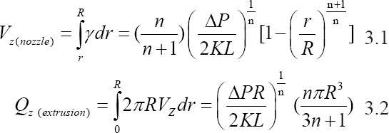
In this equation, K is the consistency index, and n is the power-law index. K is associated with the magnitude of the viscosity, and n defines the viscosity behavior; n < 1 for a shear-thinning ink[49]. As shown in Figure 3A, R is the needle radius, L is the length of the needle, and ∆P is the extrusion pressure drop along the needle. Equation 3.1 represents the velocity along the needle length; this equation shows that the velocity distribution of printed inks inside the needle is not constant. The parameter Vz(nozzle) reaches a maximum in the core of the needle and is zero at the needle wall. Equation 3.2 shows that the extrusion rate is associated with the extrusion pressure and needle radius. The filaments are formed depending on the movement of the needle in the XY plane. The printed filament can be quantitively described; it can be simplified as a cylindrical object by neglecting the spreading of the ink. There is a relationship between the extrusion rate and the printed filament speed Vnozzle(xy) within a certain period of time. The relationship among these parameters is represented in Equation 3.3[38].
Figure 3.
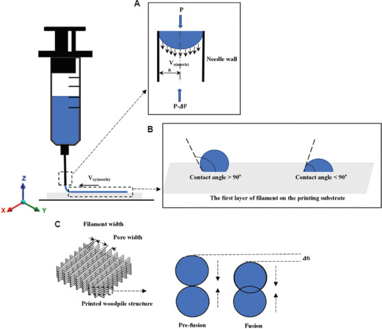
The schematic of ink flow inside the printing needle (A); the first layer of filament formation on the substrate (B); the fusion process of two filament layers in the vertical direction within the printed woodpile structure (C).

In this equation, D is the inner diameter of the applied syringe. The equation indicates that the printed filament diameter is proportional to the extrusion rate at a constant printing speed Vnozzle(xy). Ideally, the printed filament diameter should be the same as the nozzle diameter by manipulating the printing speed and extrusion rate within a defined range. If the printing speed higher than the range, the printed filament will be stretched; the filament diameter will subsequently decrease. If the printing speed lower than the range, ink accumulation will occur and the filament diameter will increase.
The substrate can affect filament formation. As shown in Figure 3B, two filaments were formed with different contact angle values on the substrate; the structure of a filament with a large contact angle value can be maintained. On the other hand, a small contact angle value can improve the stability of the scaffold. In most cases, the substrate (e.g., glass) can have large contact angles with the filament. By coating the substrate with a thin layer of one or more chemicals (e.g., polyethyleneimine), the substrate properties can be modified to decrease the contact angle[38,50]. Meanwhile, the pore geometry in the Z direction is more determined by the ink rheology, needle dimensions, and needle movement distance in the Z direction. In Figure 3 (C), ∆h is caused by two adjacent filament layers that vertically fusion together. Since the scaffold is formed in a layer-by-layer manner, a dripping ink will form at the needle tip if the distance between the needle tip and the substrate is larger; this process interrupts the continuity of filament formation. If the needle tip is too close to the substrate, the extruded filament will be scratched by the needle; as a result, the filament diameter will be increased.
Appropriate maintenance of the shape of the extruded filament is necessary to support the structure without collapsing. He et al.[19] studied ink printability by investigating filament printing of the first layer and optimized printing parameters. As shown in Figure 4A, they indicate that an overlapping problem may occur when printing filaments with different angle orientations. This problem can result in material accumulation at the overlap site and cause uneven layer heights. Furthermore, diffusion should be considered when designing scaffold. As shown in Figure 4B, the lattice structures with various pore width (DL) values were compared. The results showed that diffusion between two adjacent lines on the same layer could cause overlapping when the DL was1 mm; when the DL was 4 mm, the extent of diffusion was much less.
Figure 4.
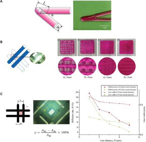
The schematic of overlap area in acute angle printing (A); the ink diffusion and fusion on the same layer when the DL was at 1-4 mm (B); the comparison of lattice area from theory and experiment as well as the relationship among line distance, line width, and diffusion rate (C)[19].
4 SBE 3D printed scaffold assessment
4.1 SBE 3D printed scaffold structure and mechanical properties
The solvents used in SBE 3D printing can cause scaffold shrinkage after drying; shrinkage can result in changes to the scaffold structural and mechanical properties. The 3D printed scaffold structures need to be evaluated before use in vitro or in vivo. There is no standardized method to quantify the difference between the theoretical CAD design and the printed structure. A common evaluation approach involves the measurement of the printed filament diameter and the filament distance from microscopy or SEM images. He et al.[19] developed a method to measure the intersection area formed by filaments in microscopy images (Figure 4C). They found that the area of the rectangle (ARe) obtained from experiments was much smaller than the theoretical rectangle area (ARt). They also investigated the relationship between filament distance and diffusion rate (φ). Micro-computed tomography (micro-CT) can also be used to evaluate the scaffold pore dimensions, porosity, and pore interconnectivity. Hockaday et al.[11] performed surface deviation analysis by micro-CT imaging of SBE 3D printed valve scaffolds with inner diameters of 22, 17, and 12 mm. The results of this study indicate that the printing accuracy decreased as the scaffold geometric size was reduced.
The SBE 3D printed scaffold should have appropriate mechanical properties (e.g., stiffness) that match with those of the host tissue. Natural polymer and synthetic polymers are often combined with bioactive materials to achieve higher mechanical strength and better biological activity. Serra et al.[35] fabricated scaffolds with two types of geometries using two groups of materials, namely PLA/PEG and PLA/PEG/bioactive CaP. The results indicate that the compressive modulus of scaffolds with bioactive CaP was higher than those without bioactive CaP for both scaffold geometries. Jakus et al.[13] formulated inks with PCL/PLGA/nano-HA mixtures; the printed scaffolds had hyperelastic characteristics. The results of the axial compressive loading showed that the scaffolds remained compliant and elastic; they underwent cycles of up to 25% compression without permanent deformation. Although scaffolds fabricated with SBE 3D printing have shown some success for bone tissue repair, the mechanical properties of the scaffolds are currently inferior to those of human cortical bone. Several studies tried to solve this problem by reinforcing the material. Srivas et al.[51] produced porous polymer/Ti6Al4V scaffolds using SBE 3D printing; the porosity and pore size of the printed scaffolds were assessed using micro-CT scanning. The results indicate that the scaffold exhibited less drying shrinkage. The compressive strength and elastic modulus values were 39.58±4.56 MPa and 450±7.21 MPa, respectively. Lacroix[52] applied a computational method to investigate the fluid dynamic environment within the micro-CT reconstructed scaffolds at the pore level. Their results indicate that the 3D printed scaffold samples did not replicate the CAD design; the generated fluid velocity and fluid shear stress magnitude for the 3D printed scaffold samples were up to 5 times higher than those for the CAD design. The variability among the 3D printed samples was also evaluated. These studies indicate that inspection methods should be used to understand the structure, mechanical properties, and mechanical properties of the printed scaffolds.
4.2 SBE 3D printed scaffold degradation and biocompatibility
Degradation and biocompatibility are important parameters that affect the use of SBE 3D printed scaffolds for tissue repair. The degradation rate of scaffold material should be controllable, allowing the scaffold to be gradually replaced by an extracellular matrix that is released by nearby cells. The degradation rate can be manipulated by optimizing the cell/hydrogel ratio. Lowering the cell density and increasing the hydrogel level can extend the degradation time. Controlling the cross-linking procedure is another approach for optimizing the degradation rate[53]. A slower degradation rate can also be obtained by increasing the degree of cross-linking in the polymer[54,55]. Mixing the polymer with other polymers can also alter the polymer degradation rate[15,56,57]. Collagen, gelatin, and alginate hydrogel constructs were printed with human corneal epithelial cells incubated with a medium containing sodium citrate to obtain degradation-controllable cell-laden tissue constructs. The results indicate that the degradation time of the bioprinting constructs can be controlled by altering the mole ratio of sodium citrate to sodium alginate. The results of this study showed that the printed cells exhibited a higher proliferation rate and greater cytokeratin-3 expression[58].
For cell-free scaffolds, the degradation rate can be controlled by incorporating various combinations of hydrophobic and hydrophilic synthetic polymers[59-61]. Bioceramics can provide a range of degradation rates; in addition, these materials are capable of stimulating biomineralization for bone tissue repair[62,63]. Kolan et al.[64] plotted PCL/bio-glass composite scaffolds with and without the presence of hydrogel; the biodegradation rate was investigated by soaking the scaffold in the culture medium. A consistently higher weight loss was noted over one week for PCL/bio-glass scaffolds printed with hydrogel in comparison to those printed without hydrogel. The combination of biodegradables material with ceramics or polymers has also been investigated[65,66]. For example, Wong et al.[66] developed a biodegradable composite composed of PCL and magnesium; they indicated that magnesium hydroxide was formed during the degradation of magnesium microparticles. This process may help to neutralize the pH since acidic by-products are produced during PCL degradation. The scaffolds containing magnesium microparticles exhibited low scaffold degradation rates; in addition, the elastic modulus of the composite scaffolds showed no differences after a 2-month immersion period. The biological results showed significantly higher specific ALP activity and upregulation of bone-related markers in the Mg/PCL scaffold than in the pure PCL scaffold.
5 Summary and future perspective
Despite the remarkable achievements of SBE 3D printing in TE, challenges remain that have prevented the translation of 3D printed scaffolds for clinical applications. First, new types of biomaterials, particularly bio-composite materials, would facilitate the clinical use of SBE 3D printing. The use of a single type of material is currently not able to produce a suitable environment for more than one functional cell type. The use of bio-composite materials in an organized pattern that matches the biodegradability, biocompatibility, and mechanical properties of natural tissue may be a more effective approach to create a suitable environment for more than one functional cell type[67].
Second, the ink rheology and processing parameters should be adjusted carefully so that multiple biomaterials and cell types can be simultaneously processed during scaffold fabrication[18]. The ink should exhibit a shear-thinning behavior and recover quickly after the extrusion from the nozzle. The filament formation process should be evaluated to confirm that the printed filament diameter is close to the needle diameter. The processing parameters should be investigated to confirm the scaffold stackability. In addition, the shear stress that the cell experiences should be evaluated. A cell damage model should be developed to investigate the cell damage caused by shear stress, which is induced by cell-cell and cell-material interactions during the printing process.
Third, there is a difference between the scaffold CAD model and SBE 3D printed scaffold after drying due to the solvent-based process; these variations also affect scaffold reproducibility. These differences can lead to unexpected variations affecting mechanical stimuli and cellular responses[68]. Micro-CT technology can be used to evaluate the scaffold pore size, porosity, and interconnectivity. Computational modeling is a cost-effective method, which can predict the mechanical stimuli that are detected by cells under in vitro or in vivo settings. Computational modeling methods and biological experiments can be used together to better understand the correlations among scaffold design, mechanical stimuli, and tissue regeneration performance[69,70].
The SBE 3D printing process begins with scaffold design, followed by biomaterial/cell ink formulation, scaffold manufacturing, scaffold culture, and implantation. The use of SBE 3D printing technologies for scaffold fabrication with or without cells remains fraught with many challenges. The ink biomaterials, ink rheology, processing parameters, and cross-linking mechanism affect the results of SBE 3D printing. Although encouraging results have been obtained from SBE 3D printing, challenges remain concerning the properties of current biomaterials, incorporation of multiple materials and cells, and poor reproducibility of the 3D printed scaffolds. Addressing these challenges will facilitate clinical translation and commercialization of SBE 3D printing.
Conflicts of interest
The authors declare that they have no conflicts of interest.
Acknowledgments
This work was supported by a grant of the Ministry of Research and Innovation, CNCS – UEFISCDI, Project Number PNIII-P4-ID-PCE-2016-0884 within PNCDI III, the Charles M. Vest National Academy of Engineering Grand Challenges for Engineering International Scholarship Program, and US National Science Foundation Award #1762202.
References
- 1.Gross BV, Erkal JL. Evaluation of 3d Printing and its Potential Impact on Biotechnology and the Chemical Sciences. Anal. Chem. 2014;86:3240–53. doi: 10.1021/ac403397r. [DOI] [PubMed] [Google Scholar]
- 2.Do AV, Khorsand B, Geary SM, et al. 3D Printing of Scaffolds for Tissue Regeneration Applications. Adv Healthc Mater. 2015;4(12):1742–62. doi: 10.1002/adhm.201500168. DOI:10.1002/adhm.201500168. [DOI] [PMC free article] [PubMed] [Google Scholar]
- 3.Wüst S, Müller R, Hofmann S. Controlled Positioning of Cells in Biomaterials Approaches towards 3D Tissue Printing. J Funct Biomater. 2011;2(3):119–54. doi: 10.3390/jfb2030119. DOI:10.3390/jfb2030119. [DOI] [PMC free article] [PubMed] [Google Scholar]
- 4.Gloria A, Russo T, De Santis R, et al. 3D Fiber Deposition Technique to Make Multifunctional and Tailor-made Scaffolds for Tissue Engineering Applications. J Appl Biomater Biomech. 2009;7(3):141–52. [PubMed] [Google Scholar]
- 5.Malda J, Woodfield TB, van der Vloodt F, et al. The Effect of PEGT/PBT Scaffold Architecture on the Composition of Tissue Engineered Cartilage. Biomaterials. 2005;26(1):63–72. doi: 10.1016/j.biomaterials.2004.02.046. DOI:10.1016/j.biomaterials.2004.02.046. [DOI] [PubMed] [Google Scholar]
- 6.Melchels FP, Tonnarelli B, Olivares AL, et al. The Influence of the Scaffold Design on the Distribution of Adhering Cells After Perfusion Cell Seeding. Biomaterials. 2011;32(11):2878–84. doi: 10.1016/j.biomaterials.2011.01.023. DOI:10.1016/j.biomaterials.2011.01.023. [DOI] [PubMed] [Google Scholar]
- 7.Phillippi JA, Miller E, Weiss L, et al. Microenvironments Engineered by Inkjet Bioprinting Spatially Direct Adult Stem Cells Toward Muscle-and Bone-like Subpopulations. Stem Cells. 2008;26(1):127–34. doi: 10.1634/stemcells.2007-0520. DOI:10.1634/stemcells.2007-0520. [DOI] [PubMed] [Google Scholar]
- 8.Woodfield T, Van Blitterswijk CA, De Wijn J, et al. Polymer Scaffolds Fabricated with Pore-size Gradients as a Model for Studying the Zonal Organization within Tissue-engineered Cartilage Constructs. Tissue Eng. 2005;11(9-10):1297–311. doi: 10.1089/ten.2005.11.1297. DOI:10.1089/ten.2005.11.1297. [DOI] [PubMed] [Google Scholar]
- 9.Gao F, Xu Z, Liang Q, et al. Direct 3D Printing of High Strength Biohybrid Gradient Hydrogel Scaffolds for Efficient Repair of Osteochondral Defect. Adv Funct Mater. 2018;28(13):1706644. DOI:10.1002/adfm.201706644. [Google Scholar]
- 10.Trachtenberg JE, Placone JK, Smith BT, et al. Extrusion-based 3D Printing of Poly (Propylene Fumarate) Scaffolds with Hydroxyapatite Gradients. J Biomater Sci Polym Ed. 2017;28(6):532–54. doi: 10.1080/09205063.2017.1286184. DOI:10.1080/09205063.2017.12↪4. [DOI] [PMC free article] [PubMed] [Google Scholar]
- 11.Hockaday L, Kang KH, Colangelo NW, et al. Rapid 3D Printing of Anatomically Accurate and Mechanically Heterogeneous Aortic Valve Hydrogel Scaffolds. Biofabrication. 2012;4(3):035005. doi: 10.1088/1758-5082/4/3/035005. DOI:10.1088/1758-5082/4/3/035005. [DOI] [PMC free article] [PubMed] [Google Scholar]
- 12.Duan B, Kapetanovic E, Hockaday LA, et al. Three-dimensional Printed Trileaflet Valve Conduits Using Biological Hydrogels and Human Valve Interstitial Cells. Acta Biomater. 2014;10(5):1836–46. doi: 10.1016/j.actbio.2013.12.005. DOI:10.1016/j.actbio.2013.12.005. [DOI] [PMC free article] [PubMed] [Google Scholar]
- 13.Jakus AE, Rutz AL, Jordan SW, et al. Hyperelastic “Bone”:A Highly Versatile, Growth Factor-free, Osteoregenerative, Scalable, and Surgically Friendly Biomaterial. Sci Transl Med. 2016;8(358):358ra127. doi: 10.1126/scitranslmed.aaf7704. DOI:10.1126/scitranslmed.aaf7704. [DOI] [PubMed] [Google Scholar]
- 14.Gonçalves RM, Pereira AC, Pereira IO, et al. Macrophage Response to Chitosan/poly-(γ-glutamic Acid) Nanoparticles Carrying an Anti-inflammatory Drug. J Mater Sci. 2015;26(4):167. doi: 10.1007/s10856-015-5496-1. DOI:10.1007/s10856-015-5496-1. [DOI] [PubMed] [Google Scholar]
- 15.Markstedt K, Mantas A, Tournier I, et al. 3D Bioprinting Human Chondrocytes with Nanocellulose-alginate Bioink for Cartilage Tissue Engineering Applications. Biomacromolecules. 2015;16(5):1489–96. doi: 10.1021/acs.biomac.5b00188. DOI:10.1021/acs.biomac.5b00188. [DOI] [PubMed] [Google Scholar]
- 16.Sun L, Parker ST, Syoji D, et al. Direct-Write Assembly of 3D Silk/Hydroxyapatite Scaffolds for Bone Co-Cultures. Adv Healthc Mater. 2012;1(6):729–35. doi: 10.1002/adhm.201200057. DOI:10.1002/adhm.201200057. [DOI] [PMC free article] [PubMed] [Google Scholar]
- 17.Lee W, Debasitis JC, Lee VK, et al. Multi-layered Culture of Human Skin Fibroblasts and Keratinocytes Through Three-dimensional Freeform Fabrication. Biomaterials. 2009;30(8):1587–95. doi: 10.1016/j.biomaterials.2008.12.009. DOI:10.1016/j.biomaterials.2008.12.009. [DOI] [PubMed] [Google Scholar]
- 18.Liu W, Zhang YS, Heinrich MA, et al. Rapid Continuous Multimaterial Extrusion Bioprinting. Adv Mater. 2017;29(3):1604630. doi: 10.1002/adma.201604630. [DOI] [PMC free article] [PubMed] [Google Scholar]
- 19.He Y, et al. Research on the Printability of Hydrogels in 3D Bioprinting. Sci Rep. 2016;6:29977. doi: 10.1038/srep29977. [DOI] [PMC free article] [PubMed] [Google Scholar]
- 20.Lewis JA, Gratson GM. Direct Writing in Three Dimensions. Mater Today. 2004;7(7-8):32–39. [Google Scholar]
- 21.Jang TS, Jung HD, Pan HW, et al. 3D Printing of Hydrogel Composite Systems:Recent Advances in Technology for Tissue Engineering. Int J Bioprint. 2018;4(1):126. doi: 10.18063/IJB.v4i1.126. [DOI] [PMC free article] [PubMed] [Google Scholar]
- 22.Ozbolat IT. Academic Press; London: 2016. 3D Bioprinting:Fundamentals, Principles And Applications. [Google Scholar]
- 23.Derakhshanfar S, Mbeleck R, Xu K, et al. 3D Bioprinting for Biomedical Devices and Tissue Engineering:A Review of Recent Trends and Advances. Bioact Mater. 2018;3(2):144–56. doi: 10.1016/j.bioactmat.2017.11.008. DOI:10.1016/j.bioactmat.2017.11.008. [DOI] [PMC free article] [PubMed] [Google Scholar]
- 24.Placone JK, Engler AJ. Recent Advances in Extrusion-Based 3D Printing for Biomedical Applications. Adv Healthc Mater. 2018;7(8):e1701161. doi: 10.1002/adhm.201701161. DOI:10.1002/adhm.201701161. [DOI] [PMC free article] [PubMed] [Google Scholar]
- 25.Schaefer D, Martin I, Jundt G, et al. Tissue-engineered Composites for the Repair of Large Osteochondral Defects. Arthritis Rheum. 2002;46(9):2524–34. doi: 10.1002/art.10493. [DOI] [PubMed] [Google Scholar]
- 26.Chen J, Chen H, Li P, et al. Simultaneous Regeneration of Articular Cartilage and Subchondral Bone in vivo Using MSCs Induced by a Spatially Controlled Gene Delivery System in Bilayered Integrated Scaffolds. Biomaterials. 2011;32(21):4793–805. doi: 10.1016/j.biomaterials.2011.03.041. DOI:10.1016/j.biomaterials.2011.03.041. [DOI] [PubMed] [Google Scholar]
- 27.Schaefer D, Martin I, Shastri P, et al. In vitro Generation of Osteochondral Composites. Biomaterials. 2000;21(24):2599–606. doi: 10.1016/s0142-9612(00)00127-7. DOI:10.1016/s0142-9612(00)00127-7. [DOI] [PubMed] [Google Scholar]
- 28.Schacht K, Jungst T, Schweinlin M, et al. Biofabrication of Cell-loaded 3D Spider Silk Constructs. Angew Chem Int Ed. 2015;54(9):2816–20. doi: 10.1002/anie.201409846. DOI:10.1002/anie.201409846. [DOI] [PubMed] [Google Scholar]
- 29.Gao G, Yonezawa T, Hubbell K, et al. Inkjet-bioprinted Acrylated Peptides and PEG Hydrogel with Human Mesenchymal Stem Cells Promote Robust Bone and Cartilage Formation with Minimal Printhead Clogging. Biotechnol J. 2015;10(10):1568–77. doi: 10.1002/biot.201400635. DOI:10.1002/biot.201400635. [DOI] [PubMed] [Google Scholar]
- 30.Müller M, Becher J, Schnabelrauch M, et al. Nanostructured Pluronic Hydrogels as Bioinks for 3D Bioprinting. Biofabrication. 2015;7(3):035006. doi: 10.1088/1758-5090/7/3/035006. DOI:10.1088/1758-5090/7/3/035006. [DOI] [PubMed] [Google Scholar]
- 31.Wüst S, Godla ME, Müller R, et al. Tunable Hydrogel Composite with Two-step Processing in Combination with Innovative Hardware Upgrade for Cell-based Three-dimensional Bioprinting. Acta Biomater. 2014;10(2):630–40. doi: 10.1016/j.actbio.2013.10.016. DOI:10.1016/j.actbio.2013.10.016. [DOI] [PubMed] [Google Scholar]
- 32.Blaeser A, Campos DF, Puster U, et al. Controlling Shear Stress in 3D Bioprinting is a Key Factor to Balance Printing Resolution and Stem Cell Integrity. Adv Healthc Mater. 2016;5(3):326–33. doi: 10.1002/adhm.201500677. DOI:10.1002/adhm.201500677. [DOI] [PubMed] [Google Scholar]
- 33.Ghosh S, Parker ST, Wang X, et al. Direct-write Assembly of Microperiodic Silk Fibroin Scaffolds for Tissue Engineering Applications. Adv Funct Mater. 2008;18(13):1883–9. DOI:10.1002/adfm.200800040. [Google Scholar]
- 34.Miranda P, Pajares A, Saiz E, et al. Mechanical Properties of Calcium Phosphate Scaffolds Fabricated by Robocasting. J Biomed Mater Res Part A. 2008;85(1):218–27. doi: 10.1002/jbm.a.31587. DOI:10.1002/jbm.a.31587. [DOI] [PubMed] [Google Scholar]
- 35.Serra T, Planell JA, Navarro M. High-resolution PLA-based Composite Scaffolds Via 3-D Printing Technology. Acta Biomater. 2013;9(3):5521–30. doi: 10.1016/j.actbio.2012.10.041. DOI:10.1016/j.actbio.2012.10.041. [DOI] [PubMed] [Google Scholar]
- 36.Gonçalves EM, Oliveira FJ, Silva RF, et al. Three-dimensional Printed PCL-hydroxyapatite Scaffolds Filled with CNTs for Bone Cell Growth Stimulation. J Biomed Mater Res Part B. 2016;104(6):1210–9. doi: 10.1002/jbm.b.33432. DOI:10.1002/jbm.b.33432. [DOI] [PubMed] [Google Scholar]
- 37.Ning L, Guillemot A, Zhao J, et al. Influence of Flow Behavior of Alginate Cell Suspensions on Cell Viability and Proliferation. Tissue Eng Part C. 2016;22(7):652–62. doi: 10.1089/ten.TEC.2016.0011. DOI:10.1089/ten.tec.2016.0011. [DOI] [PubMed] [Google Scholar]
- 38.Chen DX, Glaser C. Springer, Cham; 2019. Extrusion Bioprinting of Scaffolds for Tissue Engineering Applications. [Google Scholar]
- 39.Dávila JL, d'Ávila MA. Rheological Evaluation of Laponite/alginate Inks for 3D Extrusion-based Printing. Int J Adv Manuf Technol. 2019;101(1-4):675–86. DOI:10.1007/s00170-018-2876-y. [Google Scholar]
- 40.Liu S, Li L. Recoverable and Self-healing Double Network Hydrogel Based on κ-Carrageenan. ACS Appl Mater Interfaces. 2016;8(43):29749–58. doi: 10.1021/acsami.6b11363. DOI:10.1021/acsami.6b11363. [DOI] [PubMed] [Google Scholar]
- 41.Freeman FE, Kelly DJ. Tuning Alginate Bioink Stiffness and Composition for Controlled Growth Factor Delivery and to Spatially Direct MSC fate Within Bioprinted Tissues. Sci Rep. 2017;7(1):17042. doi: 10.1038/s41598-017-17286-1. DOI:10.1038/s41598-017-17286-1. [DOI] [PMC free article] [PubMed] [Google Scholar]
- 42.Chung JH, Naficy S, Yue Z, et al. Bio-ink Properties and Printability for Extrusion Printing Living Cells. Biomater Sci. 2013;1(7):763–73. doi: 10.1039/c3bm00012e. DOI:10.1039/c3bm00012e. [DOI] [PubMed] [Google Scholar]
- 43.Donderwinkel I, van Hest JC, Cameron NR. Bio-inks for 3D Bioprinting:Recent Advances and Future Prospects. Polym Chem. 2017;8(31):4451–71. DOI:10.1039/c7py00826k. [Google Scholar]
- 44.Li H, Tan C, Li L. Review of 3D Printable Hydrogels and Constructs. Mater Des. 2018;159:20–38. DOI:10.1016/j.matdes.2018.08.023. [Google Scholar]
- 45.Ouyang L, Yao R, Zhao Y, et al. Effect of Bioink Properties on Printability and Cell Viability for 3D Bioplotting of Embryonic Stem Cells. Biofabrication. 2016;8(3):035020. doi: 10.1088/1758-5090/8/3/035020. DOI:10.1088/1758-5090/8/3/035020. [DOI] [PubMed] [Google Scholar]
- 46.Knowlton S, Yenilmez B, Anand S, et al. Photocrosslinking-based Bioprinting:Examining Crosslinking Schemes. Bioprinting. 2017;5:10–8. DOI:10.1016/j.bprint.2017.03.001. [Google Scholar]
- 47.Schuurman W, Levett PA, Pot MW, et al. Gelatin-methacrylamide Hydrogels as Potential Biomaterials for Fabrication of Tissue-engineered Cartilage Constructs. Macromol Biosci. 2013;13(5):551–61. doi: 10.1002/mabi.201200471. DOI:10.1002/mabi.201200471. [DOI] [PubMed] [Google Scholar]
- 48.Pescosolido L, Schuurman W, Malda J, et al. Hyaluronic Acid and Dextran-based Semi-IPN Hydrogels as Biomaterials for Bioprinting. Biomacromolecules. 2011;12(5):1831–8. doi: 10.1021/bm200178w. DOI:10.1021/bm200178w. [DOI] [PubMed] [Google Scholar]
- 49.Morrison F. Oxford University Press; New York: 2001. Understanding Rheology. [Google Scholar]
- 50.You F, Wu X, Chen X. 3D Printing of Porous Alginate/gelatin Hydrogel Scaffolds and Their Mechanical Property Characterization. Int J Polym Mater Polym Biomater. 2017;66(6):299–306. DOI:10.1080/00914037.2016.1201830. [Google Scholar]
- 51.Srivas PK, Kapat K, Dadhich P, et al. Osseointegration Assessment of Extrusion Printed Ti6Al4V Scaffold Towards Accelerated Skeletal Defect Healing Via Tissue In-growth. Bioprinting. 2017;6:8–17. DOI:10.1016/j.bprint.2017.04.002. [Google Scholar]
- 52.Campos Marin A, Lacroix D. The Inter-sample Structural Variability of Regular Tissue-engineered Scaffolds Significantly Affects the Micromechanical Local Cell Environment. Interface Focus. 2015;5(2):20140097. doi: 10.1098/rsfs.2014.0097. DOI 10.1098/rsfs.2014.0097. [DOI] [PMC free article] [PubMed] [Google Scholar]
- 53.Colosi C, Shin SR, Manoharan V, et al. Microfluidic Bioprinting of Heterogeneous 3D Tissue Constructs Using Low-viscosity Bioink. Adv Mater. 2016;28(4):677–84. doi: 10.1002/adma.201503310. DOI:10.1002/adma.201503310. [DOI] [PMC free article] [PubMed] [Google Scholar]
- 54.Jeon O, Song SJ, Lee KJ, et al. Mechanical Properties and Degradation Behaviors of Hyaluronic Acid Hydrogels Cross-linked at Various Cross-linking Densities. Carbohydr. Polym. 2007;70(3):251–7. DOI:10.1016/j.carbpol.2007.04.002. [Google Scholar]
- 55.Jia W, Gungor-Ozkerim PS, Zhang YS, et al. Direct 3D Bioprinting of Perfusable Vascular Constructs Using a Blend Bioink. Biomaterials. 2016;106:58–68. doi: 10.1016/j.biomaterials.2016.07.038. DOI:10.1016/j.biomaterials.2016.07.038. [DOI] [PMC free article] [PubMed] [Google Scholar]
- 56.Duan B, Hockaday LA, Kang KH, et al. 3D Bioprinting of Heterogeneous Aortic Valve Conduits with Alginate/gelatin Hydrogels. J Biomed Mater Res. 2013;101(5):1255–64. doi: 10.1002/jbm.a.34420. DOI:10.1002/jbm.a.34420. [DOI] [PMC free article] [PubMed] [Google Scholar]
- 57.Rutz AL, Hyland KE, Jakus AE, et al. A Multimaterial Bioink Method for 3D Printing Tunable, Cell-Compatible Hydrogels. Adv Mater. 2015;27(9):1607–14. doi: 10.1002/adma.201405076. DOI:10.1002/adma.201405076. [DOI] [PMC free article] [PubMed] [Google Scholar]
- 58.Wu Z, Su X, Xu Y, et al. Bioprinting Three-dimensional Cell-laden Tissue Constructs with Controllable Degradation. Sci Rep. 2016;6:24474. doi: 10.1038/srep24474. DOI:10.1038/srep24474. [DOI] [PMC free article] [PubMed] [Google Scholar]
- 59.Ragaert K, Maeyaert G, Martins CI, et al. Bulk Compounding of PCL-PEO Blends for 3D Plotting of Scaffolds for Cardiovascular Tissue Engineering. J Mater Sci Eng. 2014;3(1) DOI:10.4172/2169-0022.1000136. [Google Scholar]
- 60.Remya K, Chandran S, Mani S, et al. Hybrid Polycaprolactone/Polyethylene Oxide Scaffolds with Tunable Fiber Surface Morphology, Improved Hydrophilicity and Biodegradability for Bone Tissue Engineering Applications. J Biomater Sci. 2018;29(12):1444–62. doi: 10.1080/09205063.2018.1465664. DOI:10.1080/09205063.2018.1465664. [DOI] [PubMed] [Google Scholar]
- 61.Lyons JG, Blackie P, Higginbotham CL. The Significance of Variation in Extrusion Speeds and Temperatures on a PEO/PCL Blend Based Matrix for Oral Drug Delivery. Int J Pharm. 2008;351(1):201–8. doi: 10.1016/j.ijpharm.2007.09.041. DOI:10.1016/j.ijpharm.2007.09.041. [DOI] [PubMed] [Google Scholar]
- 62.Kuo M, Yen S. The Process of Electrochemical Deposited Hydroxyapatite Coatings on Biomedical Titanium at Room Temperature. Mater Sci Eng C. 2002;20(1):153–60. DOI:10.1016/s0928-4931(02)00026-7. [Google Scholar]
- 63.Murugan R, Ramakrishna S. Development of Nanocomposites for Bone Grafting. Compos Sci Technol. 2005;65(15-16):2385–406. [Google Scholar]
- 64.Kolan K, Liu Y, Baldridge J, et al. Solvent Based 3D Printing of Biopolymer/Bioactive Glass Composite and Hydrogel for Tissue Engineering Applications. Procedia CIRP. 2017;65:38–43. DOI:10.1016/j.procir.2017.04.022. [Google Scholar]
- 65.Zheng Y, Gu X, Witte F. Biodegradable Metals. Mater Sci Eng. 2014;77:1–34. [Google Scholar]
- 66.Wong HM, Wu S, Chu PK, et al. Low-modulus Mg/PCL Hybrid Bone Substitute for Osteoporotic Fracture Fixation. Biomaterials. 2013;34(29):7016–32. doi: 10.1016/j.biomaterials.2013.05.062. DOI:10.1016/j.biomaterials.2013.05.062. [DOI] [PubMed] [Google Scholar]
- 67.Ning L, Chen X. A Brief Review of Extrusion-based Tissue Scaffold Bio-printing. Biotechnol J. 2017;12(8):1600671. doi: 10.1002/biot.201600671. DOI:10.1002/biot.201600671. [DOI] [PubMed] [Google Scholar]
- 68.Marin AC. Thesis. University of Sheffield; 2016. In silico Study of the Mechanisms of Cell Deposition into 3D Rapid Prototyping Scaffolds Under in vitro Hydrodynamic Conditions. [Google Scholar]
- 69.Melchels FP, Bertoldi K, Gabbrielli R, et al. Mathematically Defined Tissue Engineering Scaffold Architectures Prepared by Stereolithography. Biomaterials. 2010;31(27):6909–16. doi: 10.1016/j.biomaterials.2010.05.068. DOI:10.1016/j.biomaterials.2010.05.068. [DOI] [PubMed] [Google Scholar]
- 70.Grayson WL, Fröhlich M, Yeager K, et al. Engineering Anatomically Shaped Human Bone Grafts. Proc Natl Acad Sci. 2010;107(8):3299–304. doi: 10.1073/pnas.0905439106. DOI:10.1073/pnas.0905439106. [DOI] [PMC free article] [PubMed] [Google Scholar]