Abstract
Nanoparticles (NPs) have left their mark on the field of bioengineering. Fabricated from metallic, magnetic, and metal oxide materials, their applications include drug delivery, bioimaging, and cell labeling. However, as they enter the body, the question remains – where do they go after fulfilling their designated function? As most materials used to produce NPs are not naturally found in the body, they are not biodegradable and may accumulate overtime. There is a lack of comprehensive, long-term studies assessing the biodistribution of non-biodegradable NPs for even the most widely studied NPs. There is a clear need for NPs produced from natural materials capable of degradation in vivo. As peptides exist naturally within the human body, their non-toxic and biocompatible nature comes as no surprise. Ultrashort peptides are aliphatic peptides designed with three to seven amino acids capable of self-assembling into helical fibers within macromolecular structures. Using a microfluidics flow-focusing approach, we produced different peptide-based NPs that were then three-dimensional (3D) printed with our novel printer setup. Herein, we describe the preparation method of NPs from ultrashort self-assembling peptides and their morphology in both manual and 3D-printed hydrogels, thus suggesting that peptide NPs are capable of withstanding the stresses involved in the printing process.
Keywords: Nanoparticles, Ultrashort peptides, Self-assembly, Microfluidics, Biomaterials
1. Introduction
Given the interest surrounding nanomaterials, it is of little surprise that recent advancements have only led to an increase in the number of applications for nanoparticles (NPs) in biomedicine, optics, and electronics. Their unique size- and material-dependent properties have made them an excellent option in the search for new materials to address global challenges[1]. NPs made from semiconductors yield quantum confinement[2], whereas NPs produced from metals such as gold and silver, and magnetic materials exhibit surface plasmon resonance and superparamagnetism, respectively[3,4]. For biomedical applications, it is crucial to ensure that the material used is biocompatible and non-immunogenic to avoid inducing adverse effects within the host. Gold NPs are perhaps the most widely studied type in the realm of nanomedicine, and, however, they lack the inherent biodegradability of peptide[5-8]. As they are derived from naturally occurring amino acids, peptides are biocompatible, biodegradable, and generally non-toxic, thus an excellent material choice for the production of NPs. Self-assembling peptide has been used to form NPs of different types such as tubes, vesicles, and hydrogels[9,10]. Various preparation methods for peptide NPs exist, including pH variation, spray drying, rapid laminar jet, milling, polymer chain collapse, coacervation, and phase separation[11-18].
The intrinsic properties of a material are often dependent on its composition, and peptides are no different. One class of peptides, ultrashort peptides, is comprised peptides with no more than 7 amino acid residues, capable of self-assembly into supramolecular fibrous network structures due to their peptide motifs. Through a microfluidics flow-focusing method[19], we can prepare NPs from ultrashort peptides of different sequences for applications ranging from drug delivery to bioimaging[20,21]. This fabrication method is particularly advantageous due to its ability to continually produce peptide NPs at a scale that allows for use in experiments.
In the past, our laboratory has reported on the use of peptide hydrogels as scaffolds for tissue engineering and regenerative medicine, as well as on the preparation of hydrogels with slow-releasing silver NPs (AgNPs) for antimicrobial applications[22-25]. The addition of peptide NPs to peptide hydrogels allows for the localized delivery of any drugs or growth factors conjugated to the surface of the NPs. This is facilitated by way of a composite of sorts made entirely from a single material. In addition, we have published on our novel three-dimensional (3D) printer setup where we have explored the printability of bioinks produced in the laboratory in conjunction with various cell types[26-30]. Inspired by the potential of peptide NPs and 3D bioprinting, we decided to combine the two technologies to study the printability of our NPs. Two sequences of self-assembling peptides are tested and assessed for shape fidelity. The promising results indicate that different to the manual approach the 3D printing of ultrashort self-assembling peptide NPs may result in hydrogels embedded with a more homogenous distribution of NPs.
2. Materials and Methods
The NPs are fabricated through a microfluidic-driven flow-focusing method. The system is comprised a Dolomite 6 Junction microfluidic chip (dimensions: 45 mm × 15 mm, channel depth and width at cross-section: 50 µm × 55 µm), Nikon Eclipse TS 100 inverted microscope, Harvard Apparatus PhD Ultra syringe pump, Chemyx Fusion 200 syringe pump, and plastic syringes (BD, Luer Lok in 10 mL and 1 mL). About 50% (v/v) of ethanol solution was prepared by diluting absolute ethanol (Sigma-Aldrich) and then filtering through a Millex-GP syringe filter with a pore size of 0.22 µm. Tetrameric self-assembling peptides CH-01 and CH-02 were custom synthesized in our laboratory for nanomedicine through solid-phase peptide synthesize and purified to higher than 95% using preparative high-performance liquid chromatography.
2.1 Manual Hydrogel Sample Preparation
The CH-01 and CH-02 peptide powders were dissolved in Milli-Q water, then mixed with ×10 phosphate-buffered saline (PBS) at a final volume ratio of 9:1 (peptide solution to PBS). Gelation of both peptides occurred within a few minutes at a minimum concentration of 4 mg/mL and 3 mg/mL for CH-01 and CH-02, respectively, as shown in Figure 1. As described in section 2.3, the 3D printing system prints using a higher concentration of peptide solution as the increased viscosity enables printing at a higher resolution. Due to this, to prepare the manual hydrogel samples for these experiments, a concentration of 10 mg/mL of peptide was used to ensure a final concentration comparable to those of the printed samples. For manual sample conditions made with NPs, approximately 0.9 mg of NPs were added to the peptide solution before the addition of the PBS either by volume from the product of the microfluidic chip or in the form of lyophilized NPs.
Figure 1.
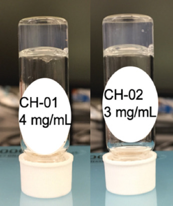
The self-assembling peptides CH-01 (4 mg/ml) and CH-02 (3 mg/ml) produce hydrogels in aqueous solution; the gelation was enhanced using phosphate-buffered saline.
2.2 NP Fabrication and Characterization
2.2.1 NP Fabrication Process
NPs were fabricated through a microfluidic flow-focusing method by way of a Dolomite 6 Junction Droplet Chip. This chip has six separate junctions that combine into one output channel for increased product. At the junction, the main channel is intersected perpendicularly by the two side channels (Figure 2A). The peptide solution in water flowing through the main channel is funneled by two side channels containing 50% (v/v) ethanol solution into a jet-like stream. The pressure from the side channels, through which 50% of ethanol in water solution (v/v) is running focuses the mainstream and leads to NP formation. Through the flow-focusing mechanism, the peptide aggregates in the water. The ultrashort peptide of a given sequence was dissolved in Milli-Q water and loaded into a 1 mL syringe to be pushed through the central channel in the junctions of the chip, and an aqueous solution of 50% filtered ethanol was loaded into a 10 mL syringe to be pushed through the side channels of the junctions, as shown in Figure 2.
Figure 2.
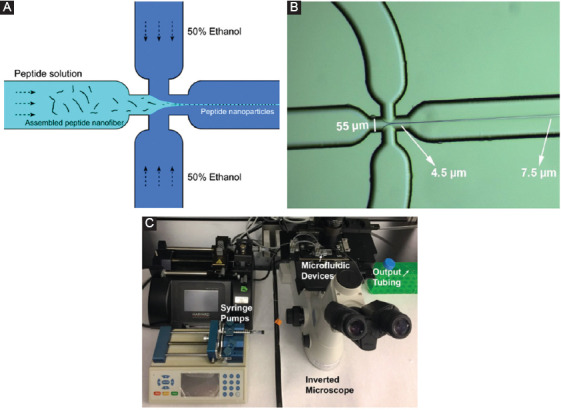
Peptide nanoparticles (NPs) preparation. Schematic representation of flow-focusing chip junctions (A), the diameter of the stream is started from 4.5 μm to higher than 7.5 μm (B), and image of the setup of the microfluidic platform for peptide NP fabrication (C).
The ratios of the flow rates of the ethanol solution to the peptide solution were found to be crucial for NP production and thus an optimization process, described in the following section, was employed to determine the ideal ratio. Before starting the actual NP production process, the microfluidic chip was stabilized by running the syringe pumps at the desired starting flow rates with the ethanol solution and with water replacing the peptide solution. This stabilization step ensures that the flow is constant and consistent across all the channels and junctions to avoid variations in morphology or decreases in NP yield due to potential blockages. Once the system started running with the peptide solution loaded, the junctions were closely watched using the optical microscope to ensure that no blockages or disruptions to the flow occur. Produced NPs were suspended in ethanol solution which was collected in a 15 mL polystyrene conical falcon tube. The NPs in solution were then frozen with liquid nitrogen and lyophilized in preparation for the printing process.
2.2.2 NP Characterization with Dynamic Light Scattering (DLS)
The NP samples were also characterized using DLS on a Zetasizer (Model X) to determine the average size. This was done during the optimization process to decide which flow rates were best for each peptide as several options were tested to obtain the largest quantity of NPs with the most uniform size distribution.
2.3 Printed Hydrogel Sample Preparation
Two vials of CH-01 and CH-02 peptide powders, 18 mg each, were weighed out and then dissolved in 1 mL of Milli-Q water by vortexing and sonicating into a homogenous solution. For the samples containing NPs, around 0.9 mg of lyophilized NPs were weighed out and dissolved in the peptide solution.
A custom-designed 3D bioprinter was set up with commercial microfluidic pumps as described in our previous publications, and a homemade two-inlet nozzle was used for extrusion[29,30]. Structures were printed directly onto 18 mm × 18 mm glass coverslips from Thermo Fischer to facilitate imaging later. Two syringe pumps were loaded for extrusion and the samples were printed into a grid construct made up of two layers using gcode.
The first syringe pump was loaded with the peptide solution and set to a flow rate of 55 µL/min. The second pump was loaded with ×5 PBS and set to a flow rate of 20 µL/min. Three samples were printed for each condition (whether CH-01 or CH-02 and printed with or without NPs) with a height of two to three layers for each sample for easier imaging. The same procedure was conducted for both peptides.
2.4 Scanning Electron Microscopy (SEM) Characterization of the Peptide NPs
During the optimization process, the peptide NPs were characterized using SEM to visualize the morphology and size distribution of the particles. Samples were prepared on SEM silicon wafers polished with acetone and isopropanol before drying with KimWipes and nitrogen gas. The silicon wafers were placed on double-stick conductive carbon tape attached to the SEM aluminum pin stub. The collected NP solutions were vortexed briefly before pipetting 15 µL of solution onto the silicon wafer. Prepared samples were left overnight to dry in a vacuum desiccator, then sputter coated with a 5 nm thickness of iridium before imaging. Images were taken with FEI Magellan XHR and FEI Quanta 600 FEG.
2.5 SEM Characterization of the Peptide Hydrogels
The peptide NPs were characterized using SEM to visualize the morphology of the NPs. This was done for samples with NPs that were printed and made manually, as well as for samples with NPs straight from the ethanol solution and those that were lyophilized to compare the integrity of the NPs. As the samples were printed on 18 × 18 mm glass coverslips, the samples were left to solidify for 10-20 min post-formation. At this point, the hydrogel samples were dehydrated by gradually immersing in increasing concentrations of 20%, 40%, 60%, 80%, and 100% (v/v) ethanol solutions for 5 min in each solution. Further, dehydration in 100% ethanol solution was continued by changing the absolute ethanol solution with a fresh one twice for 5 min each followed by the 3rd time for 2 h. The dehydrated samples were subsequently placed into the critical point dryer for evaporation before being mounted onto SEM aluminum pin stubs with double-stick conductive carbon tape and a final sputter coating of 10 nm of iridium. Images were taken with FEI Teneo SEM.
3. Results
3.1 NPs Fabrication
We first optimized the concentration of ethanol for use in the flow-focusing microfluidic platform. This was done by running the system as described above while modifying the ethanol concentration. We did this by running 1 mg/mL CH-01 through the microfluidic platform with 25%, 50%, and 75% filtered aqueous ethanol solutions at the same flow rates. The products were imaged at ×20,000, and the results can be shown in Figure 3. We then continued to optimize the flow rate ratio of the peptide and ethanol solutions for the production of peptide NPs. These experiments were done in the same way as the ethanol optimization process only changing the ratio of the flow rates used (Figure 3A and B). The parameters were selected based on fabrication throughput and a qualitative analysis of the size distribution.
Figure 3.
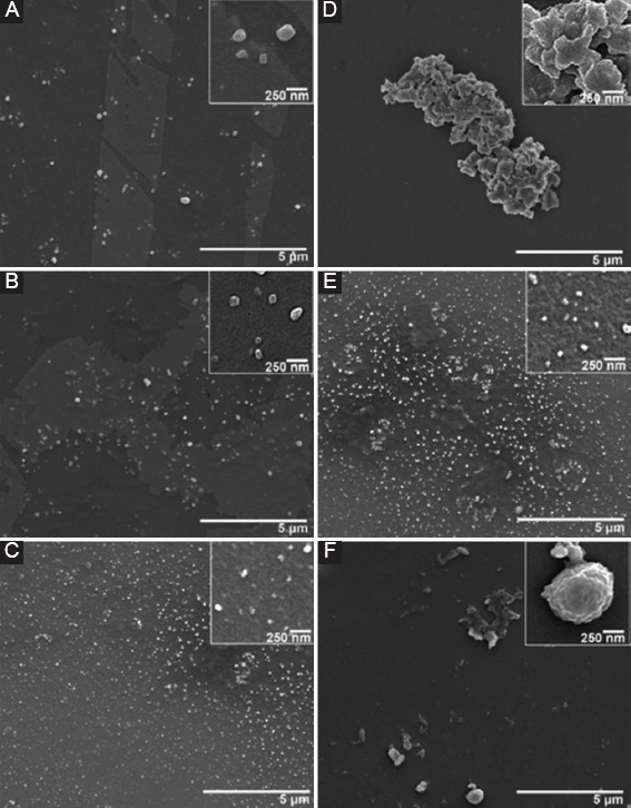
Scanning electron microscopy images of CH-01 during optimization of nanoparticles fabrication process. Left: Flow rate optimization, 1 mg/mL CH-01 run with 50% ethanol, at peptide-to-ethanol flow rate ratios of (A) 1:1 µL/min, (B) 1:5 µL/min, and (C) 1:10 µL/min. Right: Ethanol concentration optimization, 1 mg/mL CH-01 run at a peptide-to-ethanol flow rate ratio of 1:10 µL/min, with differing ethanol concentrations of (D) 25% ethanol, (E) 50% ethanol, and (f) 75% ethanol.
3.2 NPs Characterization
The prepared NPs were characterized with DLS using a Zetasizer to compare samples prepared at different flow rates. The plots of the distribution of NPs size are shown in Figure 4 and a table of the distribution analysis for the CH-01 and CH-02 NPs is presented in Table 1. The average diameter for the CH-01 NPs was measured to be around 73.05 ± 0.14 nm and that of the CH-02 NPs was found to be 73.02 ± 0.20 nm. The average size for the NPs of both peptides was observed to be very similar, around 73 nm. An explanation for this is provided in the discussion section.
Figure 4.
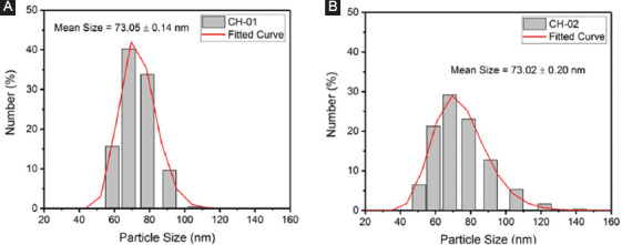
Plots of the number percent of (A) CH-01 and (B) CH-02 nanoparticles at a range of sizes obtained through dynamic light scattering.
Table 1.
Distribution analysis of NPs for CH-01 and CH-02.
| CH-01 | CH-02 | ||
|---|---|---|---|
| Size (nm) | NPs (%) | Size (nm) | NPs (%) |
| 45-55 | 0 | 45-55 | 6.48 |
| 55-65 | 15.7 | 55-65 | 21.3 |
| 65-75 | 40.3 | 65-75 | 29.1 |
| 75-85 | 33.8 | 75-85 | 23.0 |
| 85-95 | 9.67 | 85-95 | 12.7 |
| 95-105 | 0 | 95-105 | 0 |
| 105-115 | 0.414 | 105-115 | 5.33 |
| Mean: 73.05 ± 0.14 nm | Mean: 73.02 ± 0.20 nm | ||
NPs: Nanoparticles
3.3 SEM Imaging of Hydrogel Samples
The SEM imaging of the samples can be shown in Figure 5 at ×20,000 and ×80,000. The conditions imaged are as follows: CH-01 manually prepared hydrogel, CH-02 manually prepared hydrogel, CH-01 3D-printed hydrogel, CH-02 3D-printed hydrogel, CH-01 manually prepared hydrogel with lyophilized NPs, CH-02 manually prepared hydrogel with lyophilized NPs, CH-01 3D-printed hydrogel with lyophilized NPs, and CH-02 3D-printed hydrogel with lyophilized NPs. The images were taken and analyzed for NPs embedded within the hydrogel structure. This was done to confirm that the NPs did not collapse under the stress of the printing process. NPs are labeled within each sample image for easier viewing.
Figure 5.
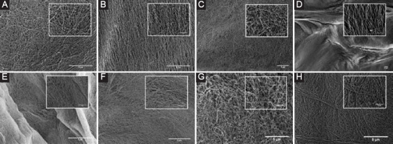
Scanning electron microscopy images taken at ×20,000 and ×80,000 (inset) of the following samples: (A) CH-01 manually prepared hydrogel, (B) CH-02 manually prepared hydrogel, (C) CH-01 manually prepared hydrogel with lyophilized nanoparticles (NPs), (D) CH-02 manually prepared hydrogel with lyophilized NPs, (E) CH-01 three-dimensional (3D) printed hydrogel, (F) CH-02 3D-printed hydrogel, (G) CH-01 3D-printed hydrogel with lyophilized NPs, and (H) CH-02 3D-printed hydrogel with lyophilized NPs.
4. Discussion
The peptide self-assembles through a combination of non-covalent interactions that are the driving force behind the observed secondary structure, and thus size and shape, of the assembled peptide molecules[31-36]. These interactions are affected by a number of parameters including the solvent choice, solvent concentration, peptide concentration, ethanol-to-peptide flow rate ratio, and the actual flow rates themselves. To assess the efficacy of each ethanol concentration tested for use in the flow-focusing microfluidic platform, the output solution for each condition was imaged using SEM. This experiment was run several times and the resulting images were compared to determine which concentration produced the largest number of homogenous NPs. From Figure 4, it is clear that the run with 50% ethanol performed the best. As such, the subsequent experiments were all performed using an optimized ethanol concentration of 50% for the side streams at each junction. Following the optimization of the ethanol concentration, the flow rate ratio of the peptide to ethanol solutions for the production of peptide NPs was also optimized using the same criteria described for the ethanol optimizations. In the experiments with lower peptide to ethanol flow rate ratios – such as 1:1 or 1:5, we observed that significantly more of the peptide formed a fiber network in the background (Figure 3A and B). Our results from several trials of these experiments suggest that as the flow rate of the ethanol increases relative to that of the peptide, more peptide NPs form. As such, the flow rate ratio of peptide to ethanol of 1:10 was used in all of the following experiments.
Characterization of the NPs using DLS revealed that the average size of both the CH-01 and CH-02 NPs was around 73.0 nm. The size distribution plot shown in Figure 4 suggests a homogenous batch of NPs, and the average size of the NPs from the DLS results is consistent with the measured sizes of the NPs seen in the SEM images in Figure 5. The similar average size for NPs produced from both peptides is due to the fact that similar parameters were used during their production with the microfluidic flow-focusing chip. As such, the original peptide solutions were subject to very similar forces and pressure from the ethanol side stream, thus resulting in similar behavior. On close examination of the SEM images of the hydrogels in Figure 5, we can draw comparisons between the size, morphology, and relative distribution of the NPs within each printed versus manually prepared hydrogel sample. As the images are quite similar, the results suggest that the NPs are capable of withstanding the stress associated with the printing process. A comparison of the manually prepared and 3D-printed samples without the addition of NPs to those made with NPs provides confirmation that the NPs observed in SEM are only present in the samples with the NPs added. The samples prepared with the addition of the NPs in ethanol solution serve as a reference to ensure that the general morphology of the NPs is not affected by the lyophilizing process.
5. Conclusion
The discovery and characterization of biomaterials suitable for use in medicine are an area of keen interest in the world of research. For tissue engineering, peptide-based hydrogels have emerged as an excellent material to serve as a scaffold that is biocompatible, biodegradable, and promotes cell proliferation and migration as it mimics the natural extracellular matrix. One of the biggest challenges with using these peptide hydrogels in conjunction with specific therapeutic molecules or growth/differentiation factors is the diffusion gradient that emerges as a result of the nanofibrous network that hinders the ability of the species to migrate to the center of the hydrogel[37]. This means that the therapeutic molecules or specific factors needed for cell growth are not evenly distributed within the sample. By producing peptide NPs modified to have these specific molecules attached to their surface[38] and by distributing these NPs throughout the hydrogel, we can overcome the diffusion gradient and allow for a slow, controlled release of these therapeutics/specific factors to the surrounding cells. The previous reports on the controlled release of NPs within a peptide hydrogel have focused on AgNPs[25] used for antimicrobial applications. The use of peptide NPs allows for the introduction of a scaffold and carriers comprised only a single foreign material to the body of the host, thus minimizing the likelihood of any adverse effects. This series of experiments serves as a proof of principle study of the ability to produce and print NPs from ultrashort self-assembling peptides into peptide-based hydrogels. Perhaps, the best way to ensure a uniform distribution of NPs within each sample is to automate the process through the use of 3D printing technology. Although future experiments are needed to further confirm and optimize the homogenous distribution of NPs within the hydrogel samples, this paves the way for an exciting future where we can possibly make use of this system for applications in medicine. One interesting area to work toward is the ability to reprogram stem cells through careful control of the ratio of each of the Yamanaka factors attached to 3D-printed peptide NPs embedded within a hydrogel scaffold[39].
Acknowledgments
The authors acknowledge Ms. Zainab Khan for her valuable contributions to the design of the 3D printing system used for these studies. We also thank Ms. Kholoud Seferji for her help in obtaining the DLS measurements. The research reported in this publication was supported by funding from King Abdullah University of Science and Technology.
Authors’ Contributions
C.A.E.H. developed the concept of ultrashort self-assembling peptides and supervised the project, S.G. wrote the manuscript, H.H.S. and S.H. optimized the NP preparation method, S.G. fabricated the NPs, H.H.S. and S.G. did the SEM imaging, K.K. printed the samples together with S.G., and H.H.S. helped with the SEM sample preparation.
Conflicts of Interest
The authors declare that they have no conflicts of interest.
References
- 1.Bobo D, Robinson KJ, Islam J, et al. Nanoparticle-Based Medicines:A Review of Materials and Clinical Trials to Date. Pharm Res. 2016;33:2373–87. doi: 10.1007/s11095-016-1958-5. DOI 10.1007/s11095-016-1958-5. [DOI] [PubMed] [Google Scholar]
- 2.Smith AW, Nie S. Semiconductor Nanocrystals. Acc Chem Res. 2010;43:190–200. doi: 10.1021/ar9001069. DOI 10.1021/ar9001069. [DOI] [PMC free article] [PubMed] [Google Scholar]
- 3.Jain PK, Huang X, El-Sayed IH, et al. Review of Some Interesting Surface Plasmon Resonance-enhanced Properties of Noble Metal Nanoparticles and Their Applications to Biosystems. Plasmonics. 2007;2:107–18. DOI 10.1007/s11468-007-9031-1. [Google Scholar]
- 4.Mikhaylova M, Kim DK, Bobrysheva N, et al. Superparamagnetism of Magnetite Nanoparticles:Dependence on Surface Modification. Langmuir. 2004;20:2472–7. doi: 10.1021/la035648e. DOI 10.1021/la035648e. [DOI] [PubMed] [Google Scholar]
- 5.Semmler-Behnke M, Kreyling WG, Lipka J, et al. Biodistribution of 1.4 and 18-nm Gold Particles in Rats. Small. 2008;4:2108–11. doi: 10.1002/smll.200800922. DOI 10.1002/smll.200800922. [DOI] [PubMed] [Google Scholar]
- 6.De Jong WH, Hagens WI, Krystek P, et al. Particle Size-dependent Organ Distribution of Gold Nanoparticles after Intravenous Administration. Biomaterials. 2008;29:1912–9. doi: 10.1016/j.biomaterials.2007.12.037. DOI 10.1016/j.biomaterials.2007.12.037. [DOI] [PubMed] [Google Scholar]
- 7.Goel R, Shah N, Visaria R, et al. Biodistribution of TNF-alpha-coated Gold Nanoparticles in an in vivo Model System. Nanomedicine. 2009;4:401–10. doi: 10.2217/nnm.09.21. DOI 10.2217/nnm.09.21. [DOI] [PMC free article] [PubMed] [Google Scholar]
- 8.Zhang G, Yang Z, Lu W, et al. Influence of Anchoring Ligands and Particle Size on the Colloidal Stability and in vivo Biodistribution of Polyethylene Glycol-coated Gold Nanoparticles in Tumor-xenografted Mice. Biomaterials. 2009;30:1928–36. doi: 10.1016/j.biomaterials.2008.12.038. DOI 10.1016/j.biomaterials.2008.12.038. [DOI] [PMC free article] [PubMed] [Google Scholar]
- 9.Sun L, Fan Z, Wang Y, et al. Tunable Synthesis of Self-assembled Cyclic Peptide Nanotubes and Nanoparticles. Soft Matter. 2015;11:3822. doi: 10.1039/c5sm00533g. DOI 10.1039/c5sm00533g. [DOI] [PubMed] [Google Scholar]
- 10.Habibi N, Kamaly N, Memic A, et al. Self-assembled Peptide-based Nanostructures:Smart Nanomaterials Toward Targeted Drug Delivery. Nano Today. 2016;11:41–60. doi: 10.1016/j.nantod.2016.02.004. DOI 10.1016/j.nanotod.2016.02.004. [DOI] [PMC free article] [PubMed] [Google Scholar]
- 11.DeFrates K, Markiewicz T, Gallo P, et al. Protein Polymer-Based Nanoparticles:Fabrication and Medical Applications. Int J Mol Sci. 2018;19:1717–36. doi: 10.3390/ijms19061717. DOI 10.3390/ijms19061717. [DOI] [PMC free article] [PubMed] [Google Scholar]
- 12.Lammel AS, Xiao H, Park SH, et al. Controlling Silk Fibroin Particle Features for Drug Delivery. Biomaterials. 2010;31:4583–91. doi: 10.1016/j.biomaterials.2010.02.024. DOI 10.1016/j.biomaterials.2010.02.024. [DOI] [PMC free article] [PubMed] [Google Scholar]
- 13.Oliveira A, Guimarães K, Cerize N, et al. Nano Spray Drying as an Innovative Technology for Encapsulating Hydrophilic Active Pharmaceutical Ingredients (API) J Nanomed Nanotechnol. 2013;4:6. DOI 10.4172/2157-7439.1000186. [Google Scholar]
- 14.Haas PA. Formation of Uniform Liquid Drops by Application of Vibration to Laminar Jets. Ind Eng Chem Res. 1992;31:959–67. DOI 10.1021/ie00003a043. [Google Scholar]
- 15.Yadav TP, Yadav RM, Singh D. Mechanical Milling:A Top down Approach for the Synthesis of Nanomaterials and Nanocomposites. Nanosci Nanotechnol. 2012;2:22–48. DOI 10.5923/j.nn.20120203.01. [Google Scholar]
- 16.Aiertza MK, Odriozola I, Cabañero G, et al. Single-chain Polymer Nanoparticles. Cell Mol Life Sci. 2011;69:337–46. doi: 10.1007/s00018-011-0852-x. DOI 10.1007/s00018-011-0852. [DOI] [PMC free article] [PubMed] [Google Scholar]
- 17.Yoon J, Kwag J, Shin TJ, et al. Nanoparticles of Conjugated Polymers Prepared from Phase-Separated Films of Phospholipids and Polymers for Biomedical Applications. Adv Mater. 2014;26:4559–64. doi: 10.1002/adma.201400906. DOI 10.1002/adma.201400906. [DOI] [PubMed] [Google Scholar]
- 18.Yang Y, Khoe U, Wang X, et al. Designer Self-assembling Peptide Nanomaterials. Nano Today. 2009;4:193–210. DOI 10.1016/j.nanotod.2009.02.009. [Google Scholar]
- 19.Karnik R, Gu F, Basto P, et al. Microfluidic Platform for Controlled Synthesis of Polymeric Nanoparticles. Nano Lett. 2008;8:2906–12. doi: 10.1021/nl801736q. DOI 10.1021/nl801736q. [DOI] [PubMed] [Google Scholar]
- 20.Ni M, Zhuo S, Iliescu C, et al. Self-assembling Amyloid-like Peptides as Exogenous Second Harmonic Probes for Bioimaging Applications. J Biophotonics. 2019;4:e201900065. doi: 10.1002/jbio.201900065. DOI 10.1002/jbio.201900065. [DOI] [PubMed] [Google Scholar]
- 21.Ni M, Tresset G, Iliescu C, et al. Microfluidics-assisted Self-assembly of Ultrashort Peptides and their Application as Theranostic Nanoparticles 2019 [Google Scholar]
- 22.Arab W, Rauf S, Al-Harbi O, et al. Novel Ultrashort Self-assembling Peptide Bioinks for 3D Culture of Muscle Myoblast Cells. Int J Bioprinting. 2018;4(2):129. doi: 10.18063/IJB.v4i2.129. DOI 10.18063/ijb.v4i2.129. [DOI] [PMC free article] [PubMed] [Google Scholar]
- 23.Arab WT, Niyas AM, Seferji K, et al. Evaluation of Peptide Nanogels for Accelerated Wound Healing in Normal Micropigs. Front Nanosci Nanotech. 2018;4(4):1–9. DOI 10.15761/fnn.1000173. [Google Scholar]
- 24.Arab WT, Kahin K, Khan Z, et al. Exploring Nanofibrous Self-assembling Peptide Hydrogels using Mouse Myoblast Cells for 3D Bioprinting and Tissue Engineering Applications. Int J Bioprinting. 2019;5(2):198. doi: 10.18063/ijb.v5i2.198. DOI 10.18063/ijb.v5i2.198. [DOI] [PMC free article] [PubMed] [Google Scholar]
- 25.Reithofer MR, Lakshmanan A, Ping ATK, et al. In situ Synthesis of Size-controlled, Stable Silver Nanoparticles within Ultrashort Peptide Hydrogels and their Anti-bacterial Properties. Biomaterials. 2014;35:7535–42. doi: 10.1016/j.biomaterials.2014.04.102. DOI 10.1016/j.biomaterials.2014.04.102. [DOI] [PubMed] [Google Scholar]
- 26.Loo Y, Lakshmanan A, Ni M, et al. Peptide Bioink:Self-assembling Nanofibrous Scaffolds for 3d Organotypic Cultures. Nano Lett. 2010;15:6919–25. doi: 10.1021/acs.nanolett.5b02859. DOI 10.1021/acs.nanolett.5b02859. [DOI] [PubMed] [Google Scholar]
- 27.Sundaramurthi D, Rauf S, Hauser CAE. 3D Bioprinting Technology for Regenerative Medicine Applications. Int J Bioprinting. 2016;2:9–16. DOI 10.18063/ijb.2016.02.010. [Google Scholar]
- 28.Loo Y, Hauser CAE. Bioprinting Synthetic Self-assembling Peptide Hydrogels for Biomedical Applications. Biomed Mater. 2016;11:114103. doi: 10.1088/1748-6041/11/1/014103. DOI 10.1088/1748-6041/11/1/014103. [DOI] [PubMed] [Google Scholar]
- 29.Khan Z, Kahin K, Rauf S, et al. Optimization of a 3D Bioprinting Process using Ultrashort Peptide Bioinks. Int J Bioprinting. 2019;5(1):173. doi: 10.18063/ijb.v5i1.173. DOI 10.18063/ijb.v5i1.173. [DOI] [PMC free article] [PubMed] [Google Scholar]
- 30.Kahin K, Khan Z, Albagami M, et al. Development of a Robotic 3D Bioprinting and Microfluidic Pumping System for Tissue and Organ Engineering. Proc SPIE. 2019;17:108750Q. DOI 10.1117/12.2507237. [Google Scholar]
- 31.Zhao X, Pan F, Xu H, et al. Molecular Self-assembly and Applications of Designer Peptide Amphiphiles. Chem Soc Rev. 2010;39:3480–98. doi: 10.1039/b915923c. [DOI] [PubMed] [Google Scholar]
- 32.Versluis F, Marsden HR, Kros A. Power Struggles in Peptide-amphiphile Nanostructures. Chem Soc Rev. 2010;39:3434–44. doi: 10.1039/b919446k. DOI 10.1039/b919446k. [DOI] [PubMed] [Google Scholar]
- 33.Lakshmanan A, Hauser CAE. Ultrasmall Peptides Self-assemble into Diverse Nanostructures:Morphological Evaluation and Potential Implications. Int J Mol Sci. 2011;12:5736–46. doi: 10.3390/ijms12095736. DOI 10.3390/ijms12095736. [DOI] [PMC free article] [PubMed] [Google Scholar]
- 34.Loo Y, Zhang S, Hauser CAE. From Short Peptides to Nanofibers to Macromolecular Assemblies in Biomedicine. Biotech Adv. 2012;30:593–603. doi: 10.1016/j.biotechadv.2011.10.004. DOI 10.1016/j.biotechadv.2011.10.004. [DOI] [PubMed] [Google Scholar]
- 35.Cui H, Webber M, Stupp S. Self-Assembly of Peptide Amphiphiles:From Molecules to Nanostrucutres to Biomaterials. Biopolymers. 2010;94:1–18. doi: 10.1002/bip.21328. DOI 10.1002/bip.21328. [DOI] [PMC free article] [PubMed] [Google Scholar]
- 36.Lakshmanan A, Zhang S, Hauser CAE. Short Self-assembling Peptides as Building Blocks for Modern Nanodevices. Trends Biotech. 2012;30:155–65. doi: 10.1016/j.tibtech.2011.11.001. DOI 10.1016/j.tibtech.2011.11.001. [DOI] [PubMed] [Google Scholar]
- 37.Hauser CAE, Zhang S. Designer Self-assembling Peptide Nanofiber Biological Materials. Chem Soc Rev. 2010;39:2780–90. doi: 10.1039/b921448h. DOI 10.1039/b921448h. [DOI] [PubMed] [Google Scholar]
- 38.Reithofer MR, Chan KH, Lakshmanan A, et al. Ligation of Anti-cancer Drugs to Self-assembling Ultrashort Peptides by Click Chemistry for Localized Therapy. Chem Sci. 2014;5:625–30. DOI 10.1039/c3sc51930a. [Google Scholar]
- 39.Liu X, Huang J, Chen T, et al. Yamanaka Factors Critically Regulate the Developmental Signaling Network in Mouse Embryonic Stem Cells. Cell Res. 2008;18(12):1177–89. doi: 10.1038/cr.2008.309. DOI 10.1038/cr.2008.309. [DOI] [PubMed] [Google Scholar]


