

A 3D printer can print a soft sensor on a deformable surface such as a breathing lung for spatiotemporal mapping of deformation.
Abstract
The ability to directly print compliant biomedical devices on live human organs could benefit patient monitoring and wound treatment, which requires the 3D printer to adapt to the various deformations of the biological surface. We developed an in situ 3D printing system that estimates the motion and deformation of the target surface to adapt the toolpath in real time. With this printing system, a hydrogel-based sensor was printed on a porcine lung under respiration-induced deformation. The sensor was compliant to the tissue surface and provided continuous spatial mapping of deformation via electrical impedance tomography. This adaptive 3D printing approach may enhance robot-assisted medical treatments with additive manufacturing capabilities, enabling autonomous and direct printing of wearable electronics and biological materials on and inside the human body.
INTRODUCTION
Three-dimensional (3D) printing technologies have been rapidly evolving over the past few decades and now include capabilities such as robocasting (1) and inkjet printing (2) that can three-dimensionally interweave a diverse palette of materials beyond hard plastics, such as 3D-printed conductors (3–5), semiconductors (6, 7), and biomaterials (8). Looking ahead, 3D printing could enable soft, compliant biomedical devices and sensors to be fabricated on the skin and inside the body, advancing portable patient monitoring (9, 10), wound treatment (11), and organ function augmentation (12). As an example, spatiotemporal measurements of lung deformation under mechanical ventilation can provide valuable information for studies of respiration mechanics (13), diagnoses of chronic lung diseases (14), and therapies for lung cancer (15).
Despite this promise, the medical impact of existing 3D printing technologies remains nascent. In medical applications, the target live biological surfaces are typically soft and undergo persistent motion and deformation. This time-varying geometry fundamentally limits the applications of existing 3D printing systems that were built upon an open-loop paradigm, in which a prescribed design is first manufactured offline on a calibrated planar substrate and then transferred to the target biological surface (1). This renders the fabrication “blinded” to the applied surface, leading to a Procrustean transfer. This is due to the mismatched interface between the as-fabricated sensors, with determinant form factors, and the target surfaces, with diverse, unique form factors that vary by user and with time. For instance, it may not be applicable to a nonplanar, dynamically morphing organ such as a lung. Moreover, fragile 3D constructs such as hydrogel materials can be disrupted during manual handling, transportation, and transplantation processes, which are susceptible to contamination. Also, manual transfer processes can result in operational inaccuracies and unpredictable human error. An alternative solution is in situ printing for seamlessly integrating the sensors on the target surface in an autonomous manner. To enable in situ printing, a new functionality is needed: a closed-loop artificial intelligence (AI) that can dynamically adapt the fabrication process by sensing the time-varying geometric states of the biological substrates in real time.
For in situ printing on a static target surface of an irregular shape, 3D scanners have been used in reverse engineering procedures to acquire accurate surface geometries for in situ printing of skin cells on wound beds (16). More recently, we developed a real-time closed-loop system that tracked the motion of a nondeforming human hand to perform in situ 3D printing of electronic tattoos directly on the skin (17). However, these approaches are not applicable when the soft tissues are undergoing complex surface deformations such as expansion and contraction. The development of a computationally efficient algorithm that can robustly and precisely track the high-dimensional deformation data is required. Here, we propose to model the space of deformation of the target surface using a shape basis model that can be learned from a dataset of 3D scans. With the learned shape model, accurate surface geometry can be recovered in 3D via a set of fiducial markers tracked by a stereo camera system. The recovered geometry is then used to dynamically adapt the 3D printing toolpath in real time.
The strain sensor for deformation measurements must be compatible with the lung tissue surface and in situ 3D printing process. Conventional sensor design strategies for spatial mapping of surface deformation are based on the dense packing of miniature sensor arrays, electrodes, and interconnects to improve the measurement resolution (18–22). This precision-demanding approach is not compatible with in situ 3D printing due to the uncertainties during printing. Alternatively, an electrical impedance tomography (EIT) sensor has a simple geometric design without sacrificing spatial resolution of sensing (23). Stretchable EIT sensors based on carbon-elastomer composites as the conductive sensing materials have previously been developed to enable multidirectional strain mapping (24). Yet, the Young’s modulus of this composite is one order of magnitude larger than lung tissue (25).
Alternatively, ionic hydrogels have high transparency and stretchability while maintaining conductivity with high-speed responses (26). Although ionic hydrogel strips have been used as linear strain sensors (27), hydrogel-based EIT sensors for continuous strain mapping have yet to be demonstrated. We incorporated an ionic hydrogel with EIT technology to enable 3D-printed wearable sensors for in situ spatiotemporal mapping of 2D volumetric strain (2D-VS). Compared with previous work with densely packed discrete sensing modules, or EIT approaches with nonconforming materials, our design approach enables a previously undiscovered design of strain sensor with several advantages, including (i) simplicity in sensor geometry, (ii) desirable sensing resolution, and (iii) ideal mechanical compliance to soft tissues. To demonstrate the closed-loop 3D printing system for real-time tracking of target deformation, a hydrogel-based EIT strain sensor was directly 3D printed on a breathing lung for in situ monitoring of deformations.
RESULTS
Real-time 3D surface tracking
We previously demonstrated real-time tracking of rigid-body motions of the target surface, including 6 degrees of freedom (DoF) in total for translation and rotation. This closed-loop strategy was shown to be effective for printing directly on moving objects without surface deformations, such as the back of a human hand (17). However, it is not applicable to dynamically morphing surfaces that require higher DoF to express their geometry. Here, we propose a previously unreported printing procedure to fabricate an EIT strain sensor on a deformable lung by integrating a visual sensing system with the 3D printer to track the time-varying 3D geometry.
A stereo camera system could be used to recover the time-varying 3D geometry of the target surface in real time. However, direct application of existing stereo reconstruction algorithms would not meet the desired specifications for closed-loop in situ 3D printing, which are (i) millimeter- or submillimeter-level precision to minimize the resultant errors that would cause collision of the dispensing nozzle into the tissue and reduce print quality or injure the tissue, (ii) short sensing range (~0.1 m) based on the restricted printing workspace, and (iii) high reconstruction rate (>5 Hz), which is an order of magnitude faster than the adult respiration rate at rest (~12 to 20 breaths/min), to minimize tracking errors. Stereo reconstruction involves exhaustive patch matching across a line of search in an image, which results in computational latency. Note that the reconstruction rate we define here not only is for the reconstruction of the geometry of each individual shape but also should provide correspondence information among a time series of shapes to represent how the shape evolves (e.g., spatial shift of feature points during deformation).
Instead of using stereo cameras to directly reconstruct the dense geometry, we used a two-phase procedure: (i) We first learned the low-dimensional parametric model of the surface geometry from a prescanned dataset offline to reduce the computational complexity for the subsequent online process; (ii) we then recovered the conformal toolpath geometry online by estimating the parameters in the offline-learned model using a sparse set of fiducial markers measured by the stereo camera in real time.
For offline learning, we adopted a structured-light 3D scanner with submillimeter-level accuracy and resolution. Multiple high-fidelity 3D scans of the deformed lung with fiducial markers were acquired by the 3D scanner (Fig. 1A). On the basis of the 3D scans, we constructed a training dataset of point clouds with pointwise correspondence among data samples and used a machine learning algorithm to learn the linear shape basis model (28–33) of the surface deformation. For online tracking, the stereo camera system consisting of a pair of synchronized machine vision cameras with high sampling rate (maximum 149 Hz) and adjustable foci (~0.1 m) tracked the fiducial markers in 3D (Fig. 1B). The marker locations allowed for the full recovery of shape deformation based on the learned deformation model. This reconstruction was used as an input to estimate the conformal toolpath for adaptive printing on a breathing lung in real time (Fig. 1C). The printed EIT strain sensor was compliant to the deformation of the lung and could provide in situ spatiotemporal mapping of lung deformation (Fig. 1D).
Fig. 1. Process of in situ 3D printing of EIT sensor on a breathing lung.
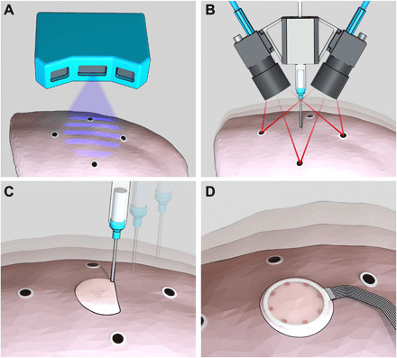
Schematic images of (A) 3D scanning of the lung surface, (B) real-time tracking of the breathing lung, (C) adaptive printing of the hydrogel ink on the breathing lung, and (D) in situ monitoring of lung deformation with the EIT sensor.
Here, we adopted the fiducial marker system to improve robustness and accuracy for tracking textureless surfaces or surfaces with sparse features and specular reflection, typical of wet anatomical surfaces. Real-time tracking of such deformable surfaces with a markerless system remains an open research area in computer vision and medical imaging (34, 35). For future improvement of our 3D surface tracking system, data-driven dense tracking approaches based on deep learning (36) and parallel computing (37) could be leveraged to enable markerless tracking.
Offline shape learning
In offline shape learning, the 3D displacement of the printing toolpath induced by the target surface deformation was modeled with respect to the movement of the fiducial markers. This allowed dynamic shape adjustment of the toolpath based on marker locations tracked by the stereo cameras during online tracking. The deformable toolpath was represented using 12 fiducial markers and 3968 toolpath waypoints in 3D. Specifically, the marker locations were extracted from the point cloud by detecting the 2D marker features in the scanned texture image and then specifying their corresponding 3D positions in the point cloud. The waypoints on the conformal toolpath were computed by projecting a planar design of the toolpath for the sensor model to each 3D-scanned point cloud of the lung surface (Fig. 2A). Before projection of the planar toolpath to obtain the waypoint correspondence among all scans, we performed a shape correction of the planar toolpath (fig. S1, A to E), such that the projected toolpath could reflect the physical growth in the size of the sensor when the surface expanded, and the shrinkage in size of the sensor when the surface contracted (Supplement 1). The distance between adjacent waypoints on the planar toolpath pattern (with a total length of 2010 mm) was set to be 0.5 mm, to replicate the detailed shape of the deformable surface with high fidelity after projection. This approach for forming the deformation training dataset with pointwise correspondence effectively reduces the dimension of the original raw point cloud data from the 3D scanner (with the number of 3D points in each scan on the scale of 105) to a lower-dimensional format consisting of only the marker locations and 3D waypoints on the printing toolpath (3980 3D points in each training data sample).
Fig. 2. Closed-loop AI for deformation estimation.
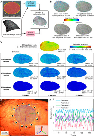
(A) Computation of conformal toolpaths from 3D scans. (B) Shape basis vectors with four largest eigenvalues in PCA analysis. Each SBV is represented by a 3D vector field (color coded by magnitude) of waypoint displacement originating from the base shape (in gray). The density of the waypoints is down-sampled by a factor of 11. The values of the maximum magnitudes are normalized by the square root of the corresponding eigenvalue for quantitative comparison under uniform scale. The visualized vector fields are scaled to fit in each subplot. (C) Position errors (in the form of norms) between the 3D scans and the estimated shapes reconstructed on the basis of two, four, and six SBVs and 3, 6, and 12 markers. (D) Snapshot image from the tracking camera, which shows real-time detection of the circular markers (blue squares as the dynamic searching windows, green contours as the circumferences of the circular markers, and green dots as the centers of the detected circles), the estimated lung pose (X, Y, and Z axes in blue, green and red, respectively), and the waypoints (blue dots) along the conformal toolpath to be followed by the tip of the nozzle. Photo credit: Z.Z., University of Minnesota. (E) Time series of four fitted deformation parameters collected from a breathing lung.
On the basis of the shape data consisting of seven point clouds of marker locations and projected toolpath waypoints, we computed the linear shape basis model using principal components analysis (PCA) (Supplement 2). The outputs of this PCA were six orthonormal shape basis vectors (SBVs), which spanned the space of the deformation field, and six corresponding eigenvalues sorted in descending order (fig. S1F and Fig. 2B).
We studied the effect of taking different numbers of SBVs and markers in the deformation model on the accuracy of shape reconstruction and found that choosing the SBVs with the four largest eigenvalues and all 12 markers for shape reconstruction resulted in a substantial reduction in estimation error compared with the rigid-body approximation (Fig. 2C and fig. S1G). Inclusion of all six SBVs in the deformation model can further reduce the estimation error on the training data. However, the resulting accuracy is unrealistic for 3D printing platforms. This may cause overfitting problems by taking the noisy deformation modes with smaller eigenvalues into consideration. Note that the shape estimation error studied here is only one source of printing error. Other sources of error include the time delays caused by data sampling, computation, and communication in the following online-tracking phase (table S1).
Online shape tracking
Two machine vision cameras (FLIR Systems) were mounted on the extrusion head for the real-time sensing process. Hand-eye calibration was first performed to specify the transformation between the camera and the 3D printer coordinate systems. During real-time tracking, circular markers on the lung surface were detected in each pair of synchronized images from the dual camera system and used to compute the 3D coordinates of the markers via stereo triangulation (Fig. 2D and movie S1). On the basis of the marker locations and the deformation model with four SBVs, four corresponding deformation parameters were fitted in real time using least squares regression. The time series of parameters can reflect the quasi-cyclic patterns of lung deformation during respiration (Fig. 2E) and were used to estimate the time-varying conformal toolpath that was adaptive to the target dynamics as a combination of rigid-body motion (approximated from the template of the base shape) and shape deformation (movies S2 and S3). Although there were circumstances when not all 12 markers were detectable by both cameras due to occlusion or exclusion from the camera field of view, the redundancy in the total number of markers guaranteed robust and precise tracking with no less than eight detectable markers. After the adaptive toolpath was transformed to the 3D printer coordinate system based on hand-eye calibration results, the extrusion nozzle followed user-specified printing speed profiles and the resampled waypoints based on an interpolation of the time series at each present time step. The adaptive printing commands for in situ 3D printing of the EIT sensor model were updated at a refresh rate of approximately 15 to 29 Hz.
Note that this deformation estimation was necessary to achieve a desirable print quality with an error tolerance of ±0.8 mm (combining the errors from the time delay and shape modeling), which was specified on the basis of the ink viscosity and the inner diameter of the extrusion nozzle (0.61 mm). The incorporation of deformation estimation reduced the mean error of shape modeling from 0.3 mm (no deformation estimation) to below 0.02 mm (Fig. 2C). This error reduction allowed the total error to be within the ±0.8 mm tolerance under a large time delay error of ~0.6 mm, computed on the basis of a time delay of ~60 ms and a point velocity of ~10 mm/s induced by the lung deformation (15).
Ionic hydrogel ink
The convergence of excellent stretchability, transparency, and conductivity renders ionic hydrogels ideal candidates for large strain sensing with EIT. Unlike opaque filler-matrix composites such as carbon embedded elastomers, which exhibit nonlinear, irreversible responses of conductivity under transient excitation (38), the conductivity of ionic hydrogels was shown to be independent of stretch (39). As a result, material conductivity can be assumed constant, such that the variation of material resistance under strain is solely determined by a geometric factor (26). This sensing mechanism enables a simple and robust computational model for repeatable and stable strain reading without requiring sophisticated algorithms to compensate for nonlinearities in material conductivity (38).
In our design of the hydrogel ink, we adopted lithium chloride (LiCl) for ion conduction due to its hydroscopic property, which prevents dehydration (40). A stretchable and ultraviolet (UV) curable polymer, polyacrylamide (PAM), was chosen as the matrix in the ionic hydrogel. The mixing ratio of monomer, polymer, and cross-linker in the hydrogel precursor was optimized for desired printability and elasticity in the 3D printing process. In the finalized ink design, shear thinning behavior was observed with decreasing viscosity above the shear rate of 0.1 s−1 (fig. S2, A and B). This lower viscosity enabled smooth extrusion of the ink from the printing nozzle under pneumatic pressure. In addition, the decreases in storage modulus (G′) and loss modulus (G″) beyond the yield shear stress (~60 Pa) improved the controllability of ink extrusion (Fig. S2C). G′ and G″ remain constant at ca. 67 and 49 Pa, respectively, when the shear stress is below the yield point, which facilitates shape retention of the printed structure.
After cross-linking using UV light, the hydrogel ink demonstrated tissue-like stretchability according to uniaxial tensile test results (fig. S3, A to D). This was further supported by dynamic mechanical characterizations in the frequency range of adult respiration at rest (~12 to 20 breaths/min), with the storage modulus (E′) and loss modulus (E″) of the hydrogel on the same order of magnitude to those of lung tissue (fig. S3, E and F). The matching of moduli holds at higher frequencies toward 2 Hz as well (fig. S3, G and H), thus extending the working conditions of this hydrogel-based sensor to a wider range of respiration rates, e.g., for patients with acute respiratory distress (41).
EIT deformable sensor
The EIT sensor consists of a continuous thin layer of hydrogel as the sensing layer and multiple copper electrodes at the boundaries (Fig. 3A). A major challenge for deformation sensing is to maintain stable hydrogel-electrode interfaces under large deformations induced by lung expansion and contraction. Here, we rectified this problem by embedding the copper electrodes in a soft silicone ring (Ecoflex 00-30, Smooth-On Inc.) that could form chemical bonds with the hydrogel (fig. S4). Specifically, the silicone surface was activated via application of benzophenone photoinitiator (BP), which generated radical sites that can react with the acrylamide in the hydrogel upon exposure to UV light. Although the silicone elastomer is stiffer than the hydrogel material (fig. S3, D to H), the resultant constraints on the stretchability of the sensor and mechanical compliance were limited because of the flexibility of its ring geometry with high aspect ratio (~1-mm thickness, 33-mm inner diameter, and 38-mm outer diameter).
Fig. 3. Design and characterization of the EIT deformable sensor.
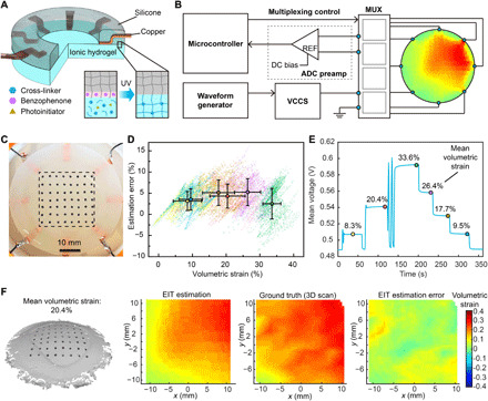
(A) Schematic image of the layered design of the hydrogel-based EIT sensor, with the inset image showing a zoom-in view of the formation of the silicone-hydrogel interface when treated with BP under UV light exposure. (B) Schematic image of the peripheral operating circuitry for the EIT system with eight electrodes. MUX, multiplexing; DC, direct current. (C) Photograph of the EIT sensor with markers for deformation validation. The rectangular region enclosed in the black dashed line demonstrates the ROI for error characterization. Photo credit: Z.Z., University of Minnesota. (D) Estimation error as a function of 2D-VS for all data points collected from six deformation states. The data points are visualized in the form of point clouds with distinct colors corresponding to different deformation states. The colored dots with black borders as well as horizontal and vertical error bars show the mean values and SDs for each deformation state (n = 1843). (E) Mean voltage measurement from all pairs of electrodes as a function of time, with the colored dots with black borders showing the six deformation states corresponding to the point clouds in (D). (F) 3D scan of the surface on the EIT sensor undergoing deformation with 20.4% mean 2D-VS, as well as the corresponding EIT estimation, ground truth from 3D scan, and EIT estimation error of the 2D-VS distribution within the ROI (left to right).
The peripheral operating circuitry of the EIT sensor consisted of a microcontroller (Teensy 3.6) for measurement control and data acquisition, a waveform generator (Rigol DG1022) and a voltage-controlled current source (VCCS) as a power supply, an ADC preamplifier for noise filtering, and input/output multiplexers for switching of electrodes for current sourcing and voltage measurements (Fig. 3B and fig. S5). The spatial distribution of sheet conductivity within the hydrogel layer was mapped by sequential four-point impedance measurements with different pairs of electrodes for current sourcing and voltage measurement. Ionic hydrogels were used as electrolytes for ionic conduction (26). Upon application of a voltage potential at the electrode/hydrogel electrolyte interface, an electrical double layer was formed at the interface between the electrode and hydrogel (26), which is equivalent to a capacitor in series with the conductive sensing layer. Thus, an alternating current (AC) source with low amplitude (less than 1 mA) was applied to avoid an electrochemical reaction and eliminate the effect of capacitor impedance (26, 27). Similar methods to measure electrical impedance with AC sources have been used for ionic conduction in liquid and solid electrolytes (42). Since the conductivity of the conductive layer (~20 S/m) was more than one order of magnitude higher than the lung tissue (43), current leakage to the tissue was not substantial when low current levels were applied and had negligible impact on organ behavior and measurement results.
The distribution of sheet conductivity within the sensing layer was computed by solving the inverse problem of a finite element model based on the impedance measurements from the electrodes (44). The size of the triangular mesh in the finite element model is approximately 1.4 mm in side length, resulting in a spatial resolution comparable to those in the literature involving lung shape reconstruction based on computed tomography (CT) scans (45, 46). The strain map was then estimated on the basis of the correlation between sheet conductivity and 2D-VS, which was modeled as
Here, σ0 and σt are local sheet conductivities of an infinitesimal region before and after deformation. εA is 2D-VS defined by εA = (At − A0)/A0, with A0 and At denoting the surface areas of the infinitesimal region before and after deformation, respectively. Because the Poisson’s ratio of PAM-based hydrogels is close to 0.5 (47), the conductive layer was approximated as an incompressible material in this estimation model (Supplement 3).
To verify this model with the EIT configuration of eight electrodes and circular sensing region, we compared the EIT strain mapping results with the ground truth on a custom-built test bed. The test bed consisted of a rubber membrane with a soft EIT sensor adhering to it and a pneumatic system that controlled the expansion and contraction of the membrane (fig. S6, A to C). Forty measurements were taken from adjacent pairs of electrodes for one complete estimation of the strain map (fig. S6D), which was refreshed at a frequency of 2.5 Hz in real time (movie S4). The ground truth distribution of 2D-VS was acquired by tracking the motions of markers attached to the surface of the EIT sensor with a 3D scanner (Fig. 3C). To characterize strain mapping errors under different levels of surface deformation, we recorded spatiotemporal sensor responses as well as the corresponding ground truth 2D-VS ranging from −3.54 to 41.6% in six sampled shapes (Fig. 3, D and E). This range of 2D-VS is on the same scale of the range of lung deformation collected from human subjects (48). The estimation error was computed by subtracting the EIT estimation from the ground truth of strain map in each sampled shape (Fig. 3F and fig. S7). According to the characterization results, the mean estimation error was independent of the strain level, with the maximum mean error of 5.25%. The relative error of strain estimation computed on the basis of the definition in (46) was 6.72% under the largest tested mean 2D-VS (33.55%). This is comparable to the results under similar strain levels in CT-based reconstruction approaches using a finite element method and a B-spline method (46). This EIT-based sensing approach provides an alternative method for direct, localized measurement of lung deformation, and can complement noninvasive approaches such as CT scanning in medical applications. The EIT estimation accuracy could be further improved by (i) optimizing printing fidelity to minimize geometric discrepancy between the fabricated sensor and the EIT computational model, (ii) increasing the number of electrodes for larger numbers of voltage measurements to reduce the computational error for inverse solving of the ill-posed EIT problem, and (iii) improving the robustness of current sourcing and voltage measurement systems to compensate for noises and disturbances during the signal processing phase.
In situ deformation monitoring
We demonstrated the in situ 3D printing capability of the AI-powered 3D printing system by directly fabricating the EIT strain sensor on a porcine lung (BioQuest) undergoing respiration-induced deformation. First, temporal tracking markers with black circular dots on a white background were attached to the lung surface via biocompatible adhesives (Skin Tite, Smooth-On) to serve as robust features for computer vision–based tracking. To simulate the deformation of the porcine lung in vitro, the trachea was connected to the output of a digital pneumatic regulator (Nordson EFD), which was programmed by a computer to controllably supply air to the alveoli. Each level of supplied pressure resulted in a respiration state and a corresponding shape deformation of the lung. The surface geometry under each deformation state was then sampled by a structured light scanner (HDI 109, LMI Technologies) to form the dataset for the machine learning algorithm to learn the deformation model (Fig. 4A).
Fig. 4. 3D printing on a porcine lung for in situ monitoring of deformation and 3D printing on a deformable phantom face.
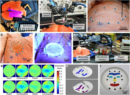
(A) 3D scanning of the porcine lung with a structured light 3D scanner. Photo credit: Z.Z., University of Minnesota. (B) Photograph of the custom-built 3D printing gantry system. Photo credit: Z.Z., University of Minnesota. (C) Photograph of in situ 3D printing of hydrogel ink on a porcine lung. Photo credit: Z.Z., University of Minnesota. (D) Photograph of the 3D printed circular layer of hydrogel. Photo credit: Z.Z., University of Minnesota. (E) UV light curing of the hydrogel layer with the silicone ring and embedded electrodes. Photo credit: Z.Z., University of Minnesota. (F) Photograph of the hardware setup for in situ monitoring of lung deformation with the printed EIT sensor. Photo credit: Z.Z., University of Minnesota. (G) Spatiotemporal mapping results of 2D-VS within the ROI on a porcine lung undergoing cyclic contraction. (H) Projection of the toolpath (in blue) on the 3D scan of the base shape (upper), and projection of the toolpath with (in blue) and without (in red) shape correction on the 3D scan of a deformed shape of the phantom face (lower). The three reference axes (in green) were used to estimate the surface expansion ratio for shape correction. (I) Photograph of the 3D-printed eyebrow, eyes, nose, and mouth on the phantom face with multicolored silicone inks. Photo credit: Z.Z., University of Minnesota.
The custom-built printing platform consisted of a 3D printing gantry system with micrometer-level motion control precision (AGS1000, AeroTech), a material extrusion system controlled by a pneumatic regulator, two machine vision cameras (FLIR Systems) mounted on the extrusion head for vision-based tracking, and an illumination system assisting the camera system for optimal image quality (Fig. 4B). During printing, the lung underwent continuous deformations with a respiration rate of about 12 breaths/min, which was controlled by a cyclic pressure input from the pneumatic regulator (Fig. 4C and movie S5). Note that this prior information of breathing actuation was not used for the real-time tracking algorithm. Adaptive 3D printing of the EIT deformation sensor was only based on the real-time image streams from the tracking cameras and the learned deformation model, resulting in a circular layer of hydrogel on the lung (Fig. 4D) with mean printing error of 0.657 mm (fig. S8A). The electrodes embedded in the silicone ring were then attached to the printed layer and exposed to UV light (OmniCure model S1500; wavelength, 320 to 500 nm) for cross-linking of the hydrogel (Fig. 4E). A stable hydrogel-electrode interface was also achieved via the formation of silicone-hydrogel bonds during UV light curing. The interface was tested to be able to survive substantial mechanical stretches (movie S6).
To demonstrate in situ deformation monitoring with the 3D-printed EIT sensor, the electrodes were connected to power supplies and a desktop computer via the peripheral circuitry for signal processing (Fig. 4F). Spatial mapping of 2D-VS was estimated and displayed in real time (movie S7), which captured the cyclic contraction of the region of interest (ROI) (Fig. 4G). The EIT sensor was able to adhere to the lung surface under repetitive deformation. After the functions of the sensor were fulfilled, the hydrogel layer and the tracking markers together with the biocompatible adhesives could be removed using a tweezer without leaving any noticeable residue (fig. S8, B to D).
Multimaterial printing on phantom face
To demonstrate the capability to print multiple materials on a deformable target surface comprising a complicated geometry consisting of convex and concave features, colored silicone inks were printed on a deformable phantom consisting of a silicone film with a casted face geometry. Twelve tracking markers were distributed on the phantom face for visual tracking before 3D scanning was performed to sample eight deformed shapes of the phantom face. Planar toolpaths for features of the eyebrow, eyes, nose, and mouth were then projected to the 3D scans to form the training dataset (Fig. 4H). Because of the higher complexity in the deformation behavior of the phantom face due to a nonuniform distribution of thickness (hence stiffness) on the membrane, all the SBVs from the PCA analysis were used for real-time shape reconstruction to capture as many modes of deformation as possible. Silicone inks (Ecoflex 00-30, Smooth-On) colored by four types of color pigments (Silc Pig, Smooth-On) were directly printed on the phantom face undergoing expansion and contraction driven by a pneumatic system (movie S8). The resulting mean tracking error was 0.841 mm, with an SD of 0.350 mm, demonstrating spatial control capability of the closed-loop 3D printing system for multimaterial printing of irregular patterns on a complex shape (Fig. 4I). The lower printing precision compared with that of printing on the porcine lung was a consequence of the higher approximation error during reconstruction of the complex geometry with the limited size of the training dataset.
DISCUSSION
We demonstrated in situ monitoring of lung deformation with a soft sensor that was 3D printed in vitro on a breathing lung. This was realized by the development of an AI-powered 3D printing system that can adapt to the deformation and motion of the target surface, as well as the unique design of a hydrogel-based EIT sensor for spatiotemporal mapping of 2D-VS. In the development of the adaptive 3D printing system, we showed the effectiveness of the approach to estimate surface deformation in the form of a dynamic point cloud, by combining “offline” machine learning with “online” computer vision–based tracking. In the sensor design, we integrated a conductive hydrogel ink with an EIT sensing configuration to enable additive manufacturing of stretchable strain sensors with mechanical compliance to the lung surface and superior sensing resolution. In situ 3D printing of functional devices and materials on and inside human bodies could stimulate a new frontier of surgical robotics in tandem with additive processing. This could aid modern medical treatments in myriad ways, such as printing electrode arrays for neural interfaces and printing bioscaffolds with engineered cells for tissue regeneration (49). For instance, in clinical applications where injections of biological materials such as surgical glue (50) and skin grafts (49) are required, in situ autonomous 3D printing could replace manual operation, which is often inconsistent under different printing scenarios, to achieve precise spatial control over long time durations. Future studies will focus on the following: (i) investigating and improving the biocompatibility of the hydrogel sensors with in vivo experiments, (ii) optimizing the material system for fully 3D printed electrode interfaces with improved adhesion and mechanical compliance, (iii) developing portable and noninvasive untethered solutions for supplying power and communicating data with the sensor, (iv) improving printing precision by incorporating advanced AI such as predictive algorithms to anticipate future deformations and motions, and (v) deploying the in situ printing controller on minimally invasive robotic platforms for surgical applications.
MATERIALS AND METHODS
Hydrogel ink design
The final design of the hydrogel ink for additive manufacturing of EIT strain sensors consisted of 7.9 weight % (wt %) acrylamide as the monomer, 3.16 wt % PAM (MW = 5,000,000) as the rheology modifier, 21.48 wt % LiCl, 0.13 wt % N,N′-methylenebisacrylamide as the cross-linker, 0.08 wt % 2-hydroxy-2-methylpropiophenone as the photoinitiator, and 37.6 wt % ethylene glycol along with 29.64 wt % ultrapure water as the solvents.
EIT sensor material preparation
The ionic hydrogel ink was prepared by first dissolving LiCl and acrylamide monomer (Sigma-Aldrich) in deionized water, followed by the addition of ethylene glycol (Fisher Chemical). After a homogeneous solution was formed via thorough mixing, PAM (Sigma-Aldrich) was added to the solution and then magnetically stirred overnight at 60°C at 1200 rpm. Last, N,N′-methylenebisacrylamide (Sigma-Aldrich) and 2-hydroxy-2-methylpropiophenone (Sigma-Aldrich) were added to the solution and magnetically stirred for 2 hours. After loading into a syringe for 3D printing, the ink was defoamed in a planetary centrifugal mixer (Thinky ARM-310) at 2200 rpm.
Silicone elastomer was prepared by mixing parts A and B of Ecoflex 00-30 (Smooth-On) with a ratio of 1:1 and then casted between two plastic petri dishes with 1-mm spacer in the middle. The surface of each petri dish was coated with a release agent (Smooth-On) before casting. After curing under room temperature for 4 hours, the silicone film was cut into ring shapes using a laser cutter (Universal Laser Systems).
Mechanical and rheological characterizations
Rheological characterization of hydrogel ink (uncross-linked) was performed using a TA Instruments DHR-3 rotational rheometer with cone (40 mm, 2°) and plate geometry. Viscometry tests were performed at shear rates from 10−1 to 102 s−1, and oscillatory rheometry tests were performed at a frequency of 1 Hz and oscillatory stresses from 10−1 to 103 Pa.
Uniaxial tensile tests were performed on porcine lung tissue specimens, 3D-printed hydrogel specimens, and casted silicone specimens using a TA Instruments RSA-G2 extensional dimethylamine (DMA) rheometer. The tissue specimens were cut into rectangular shapes and tested within 12 hours after the lung tissue was taken from the animal. Before testing, the tissue specimens were stored in saline solution in the refrigerator. Static stress-strain curves were acquired for each material at a strain rate of 0.1 mm/s. Oscillatory tensile tests with strain sweep were conducted at strains from 1 to 5% and at frequencies of 0.2 and 0.3 Hz. Oscillatory tensile tests with frequency sweep were conducted at frequencies from 0.2 to 2 Hz and at strains of 2 and 5%.
EIT system configuration
Switching of electrodes for current sourcing and voltage measurement was controlled using CD74HC4067 multiplexers. Alternating current with a frequency of 20 kHz and amplitude of 0.8 mA was supplied to the EIT sensor by a Howland Current Pump consisting of an LT6375 amplifier and a RIGOL DG1022 waveform generator. The voltage measurements from the electrode pairs were amplified 74× using an INA 128 amplifier. To dampen ambient electromagnetic interference such as fluorescent light ballasts (e.g., 50 kHz) and power line noise (e.g., 60 Hz), the amplified signal was filtered by a low pass filter with a cutoff frequency at 31.2 kHz, followed by a high pass filter with a cutoff frequency at 4.8 kHz. The filtered signal was eventually biased by 1.65 V (INA 111AP) and amplified by five times (INA 128) before it was fed to the 12-bit ADC (analog-to-digital converter) input port of the microcontroller.
The microcontroller was programmed to acquire 40 voltage measurements (adjacent stimulation and measurement patterns in the eight-electrode configuration) for each update of EIT estimation. For each voltage measurement, the ADC module collected 100 samples of voltage signal at a frequency of 400 kHz (covering approximately five periods of the 20 kHz AC signal) for a root-mean-square estimation of the voltage amplitude, followed by a wait period of 10 ms before configuring for the next voltage measurement.
We developed the deformation estimation software based on the EIDORS toolkit in MATLAB. Specifically, a one-step Gauss-Newton inverse model with a NOSER prior was adopted for reconstruction of conductivity distribution. The hyperparameter and background value for the inverse model was set on the basis of the measured conductivity of the hydrogel (inferred from the prior EIT data of the undeformed hydrogel sensor).
EIT strain sensor characterization
The test bed for the EIT sensor characterization consists of a rigid frame (3D printed with polylactic acid), a rubber membrane layer (McMaster-Carr) with its boundary fixed to the frame, as well as a balloon beneath the rubber membrane and connected to the digital pneumatic regulator (Nordson EFD). A hydrogel EIT sensor was attached to the rubber membrane via silicone adhesive (Loctite). Fifty-six paper markers in black were attached to the top surface of the EIT sensor. We used a 3D scanner to register the 3D positions of marker centers, which were configured as nodes in the computational model to construct a triangular surface mesh on the EIT sensor. The ground truth 2D volumetric strain within each triangular mesh element was approximated by computing the area expansion ratio of the triangular region.
Direct writing on a porcine lung
The hydrogel ink was printed on the porcine lung with a printing speed of 6 mm/s, an extrusion pressure of 200 kPa, an extrusion nozzle with inner diameter of 0.61 mm, and a 1-mm gap between the extrusion nozzle and lung surface. The maximum traversing speed of the 3D printer was set to be 500 mm/s for each moving axis. The digital pneumatic regulator that controlled lung deformation was configured to output 24-kPa pressure in the form of a square pulse wave, with a pulse width of 80% and a frequency of 0.2 Hz. The central control software for real-time tracking of deformation and adaptive 3D printing was programmed in C++ and run on a desktop with 3.5 GHz Intel Xeon E5 processor and 16 GB RAM.
Direct writing on a phantom face
The test bed for the deformable phantom face consists of a rigid frame (3D printed with polylactic acid), a casted silicone phantom face model with its boundary fixed to the frame, as well as a balloon beneath the rubber membrane and connected to the digital pneumatic regulator (Nordson EFD). The casted silicone material was prepared by adding 3 wt % of white pigments (Silc Pig, Smooth-On) to the mixture of parts A and B of Ecoflex 00-30 (Smooth-On) at a ratio of 1:1. The casted structure was cured under room temperature for 4 hours before release from the mold.
The colored silicone inks were prepared by first mixing parts A and B of Ecoflex 00-30 (Smooth-On) with a ratio of 1:1, and then adding 3 wt % of thickener (THI-VEX, Smooth-On) and 3 wt % of blue, red, green, and yellow pigments (Silc Pig, Smooth-On) to form 3D-printable, multicolored silicone inks. The inks were thoroughly mixed in a planetary centrifugal mixer (Thinky ARM-310) before being loaded into the printing syringe. The printed features on the phantom face were cured under room temperature for 4 hours.
Supplementary Material
Acknowledgments
We thank W. Upchurch from the University of Minnesota (UMN) Visible Heart Lab (VHL) for assistance in acquiring porcine lung tissue, and D. Giles for assistance with the mechanical and rheological characterizations carried out in the UMN Polymer Characterization Facility. Funding: Research reported in this publication was supported by Medtronic plc (for sensor development) and the National Institute of Biomedical Imaging and Bioengineering of the NIH under award number DP2EB020537. The content is solely the responsibility of the authors and does not necessarily represent the official views of Medtronic plc nor the NIH. Z.Z. acknowledges support from the graduate school of the University of Minnesota (2019–2020 Doctoral Dissertation Fellowship). Author contributions: Z.Z. and M.C.M. conceived the research. Z.Z. designed and performed the experiments and analyzed the experimental results. All authors composed and reviewed the manuscript. Competing interests: Z.Z. and M.C.M. are inventors on a pending U.S. patent application related to this work filed by the University of Minnesota (“Additive Manufacturing on Unconstrained Freeform Surfaces,” U.S. patent application 16/460,194.) M.C.M. is on the editorial board of Science Advances. The authors declare that they have no other competing interests. Data and materials availability: All data needed to evaluate the conclusions in the paper are present in the paper and/or the Supplementary Materials. Additional supporting data are available at the data repository for the University of Minnesota (https://doi.org/10.13020/vqfp-vq57) and from the authors upon request.
SUPPLEMENTARY MATERIALS
Supplementary material for this article is available at http://advances.sciencemag.org/cgi/content/full/6/25/eaba5575/DC1
REFERENCES AND NOTES
- 1.Valentine A. D., Busbee T. A., Boley J. W., Raney J. R., Chortos A., Kotikian A., Berrigan J. D., Durstock M. F., Lewis J. A., Hybrid 3D printing of soft electronics. Adv. Mater. 29, 1703817 (2017). [DOI] [PubMed] [Google Scholar]
- 2.Lu B., Lan H., Liu H., Additive manufacturing frontier: 3D printing electronics. Opto-Electron. Adv. 1, 170004 (2018). [Google Scholar]
- 3.Qiu K., Zhao Z., Haghiashtiani G., Guo S.-Z., He M., Su R., Zhu Z., Bhuiyan D. B., Murugan P., Meng F., Park S. H., Chu C.-C., Ogle B. M., Saltzman D. A., Konety B. R., Sweet R. M., McAlpine M. C., 3D printed organ models with physical properties of tissue and integrated sensors. Adv. Mater. Technol. 3, 1700235 (2018). [DOI] [PMC free article] [PubMed] [Google Scholar]
- 4.Guo S.-Z., Qiu K., Meng F., Park S. H., McAlpine M. C., 3D printed stretchable tactile sensors. Adv. Mater. 29, 1701218 (2017). [DOI] [PMC free article] [PubMed] [Google Scholar]
- 5.Li L., Pan L., Ma Z., Yan K., Cheng W., Shi Y., Yu G., All inkjet-printed amperometric multiplexed biosensors based on nanostructured conductive hydrogel electrodes. Nano Lett. 18, 3322–3327 (2018). [DOI] [PubMed] [Google Scholar]
- 6.Park S. H., Su R., Jeong J., Guo S.-Z., Qiu K., Joung D., Meng F., McAlpine M. C., 3D printed polymer photodetectors. Adv. Mater. 30, 1803980 (2018). [DOI] [PMC free article] [PubMed] [Google Scholar]
- 7.Kong Y. L., Tamargo I. A., Kim H., Johnson B. N., Gupta M. K., Koh T.-W., Chin H.-A., Steingart D. A., Rand B. P., McAlpine M. C., 3D printed quantum dot light-emitting diodes. Nano Lett. 14, 7017–7023 (2014). [DOI] [PubMed] [Google Scholar]
- 8.Joung D., Truong V., Neitzke C. C., Guo S.-Z., Walsh P. J., Monat J. R., Meng F., Park S. H., Dutton J. R., Parr A. M., McAlpine M. C., 3D printed stem-cell derived neural progenitors generate spinal cord scaffolds. Adv. Funct. Mater. 28, 1801850 (2018). [DOI] [PMC free article] [PubMed] [Google Scholar]
- 9.Feiner R., Dvir T., Tissue–electronics interfaces: From implantable devices to engineered tissues. Nat. Rev. Mater. 3, 17076 (2018). [Google Scholar]
- 10.Kenry, Yeo J. C., Lim C. T., Emerging flexible and wearable physical sensing platforms for healthcare and biomedical applications. Microsyst. Nanoeng. 2, 16043 (2016). [DOI] [PMC free article] [PubMed] [Google Scholar]
- 11.Vijayavenkataraman S., Lu W. F., Fuh J. Y. H., 3D bioprinting of skin: A state-of-the-art review on modelling, materials, and processes. Biofabrication 8, 032001 (2016). [DOI] [PubMed] [Google Scholar]
- 12.Roche E. T., Horvath M. A., Wamala I., Alazmani A., Song S.-E., Whyte W., Machaidze Z., Payne C. J., Weaver J. C., Fishbein G., Kuebler J., Vasilyev N. V., Mooney D. J., Pigula F. A., Walsh C. J., Soft robotic sleeve supports heart function. Sci. Transl. Med. 9, eaaf3925 (2017). [DOI] [PubMed] [Google Scholar]
- 13.Blankman P., Hasan D., Bikker I. G., Gommers D., Lung stress and strain calculations in mechanically ventilated patients in the intensive care unit. Acta Anaesth. Scand. 60, 69–78 (2016). [DOI] [PMC free article] [PubMed] [Google Scholar]
- 14.Frerichs I., Amato M. B. P., van Kaam A. H., Tingay D. G., Zhao Z., Grychtol B., Bodenstein M., Gagnon H., Böhm S. H., Teschner E., Stenqvist O., Mauri T., Torsani V., Camporota L., Schibler A., Wolf G. K., Gommers D., Leonhardt S., Adler A.; TREND study group , Chest electrical impedance tomography examination, data analysis, terminology, clinical use and recommendations: Consensus statement of the translational eit development study group. Thorax 72, 83–93 (2017). [DOI] [PMC free article] [PubMed] [Google Scholar]
- 15.Chhatkuli S., Koshizuka S., Uesaka M., Dynamic tracking of lung deformation during breathing by using particle method. Modell. Simul. Eng. 2009, 190307 (2009). [Google Scholar]
- 16.Albanna M., Binder K. W., Murphy S. V., Kim J., Qasem S. A., Zhao W., Tan J., El-Amin I. B., Dice D. D., Marco J., Green J., Xu T., Skardal A., Holmes J. H., Jackson J. D., Atala A., Yoo J. J., In situ bioprinting of autologous skin cells accelerates wound healing of extensive excisional full-thickness wounds. Sci. Rep. 9, 1856 (2019). [DOI] [PMC free article] [PubMed] [Google Scholar]
- 17.Zhu Z., Guo S.-Z., Hirdler T., Eide C., Fan X., Tolar J., McAlpine M. C., 3D printed functional and biological materials on moving freeform surfaces. Adv. Mater. 30, e1707495 (2018). [DOI] [PMC free article] [PubMed] [Google Scholar]
- 18.Xu L., Gutbrod S. R., Bonifas A. P., Su Y., Sulkin M. S., Lu N., Chung H.-J., Jang K.-I., Liu Z., Ying M., Lu C., Webb R. C., Kim J.-S., Laughner J. I., Cheng H., Liu Y., Ameen A., Jeong J.-W., Kim G.-T., Huang Y., Efimov I. R., Rogers J. A., 3D multifunctional integumentary membranes for spatiotemporal cardiac measurements and stimulation across the entire epicardium. Nat. Commun. 5, 3329 (2014). [DOI] [PMC free article] [PubMed] [Google Scholar]
- 19.Sun Q., Seung W., Kim B. J., Seo S., Kim S.-W., Cho J. H., Active matrix electronic skin strain sensor based on piezopotential-powered graphene transistors. Adv. Mater. 27, 3411–3417 (2015). [DOI] [PubMed] [Google Scholar]
- 20.Zhao X., Hua Q., Yu R., Zhang Y., Pan C., Flexible, stretchable and wearable multifunctional sensor array as artificial electronic skin for static and dynamic strain mapping. Adv. Electron. Mater. 1, 1500142 (2015). [Google Scholar]
- 21.Li X., Yang T., Yang Y., Zhu J., Li L., Alam F. E., Li X., Wang K., Cheng H., Lin C.-T., Fang Y., Zhu H., Large-area ultrathin graphene films by single-step marangoni self-assembly for highly sensitive strain sensing application. Adv. Funct. Mater. 26, 1322–1329 (2016). [Google Scholar]
- 22.Glauser O., Panozzo D., Hilliges O., Sorkine-Hornung O., Deformation capture via soft and stretchable sensor arrays. ACM Trans. on Graphics 38, 16 (2019). [Google Scholar]
- 23.Silvera-Tawil D., Rye D., Soleimani M., Velonaki M., Electrical impedance tomography for artificial sensitive robotic skin: A review. IEEE Sensors J. 15, 2001–2016 (2014). [Google Scholar]
- 24.Lee H., Kwon D., Cho H., Park I., Kim J., Soft nanocomposite based multi-point, multi-directional strain mapping sensor using anisotropic electrical impedance tomography. Sci. Rep. 7, 39837 (2017). [DOI] [PMC free article] [PubMed] [Google Scholar]
- 25.Polio S. R., Kundu A. N., Dougan C. E., Birch N. P., Aurian-Blajeni D. E., Schiffman J. D., Crosby A. J., Peyton S. R., Cross-platform mechanical characterization of lung tissue. PLOS ONE 13, e0204765 (2018). [DOI] [PMC free article] [PubMed] [Google Scholar]
- 26.Keplinger C., Sun J.-Y., Foo C. C., Rothemund P., Whitesides G. M., Suo Z., Stretchable, transparent, ionic conductors. Science 341, 984–987 (2013). [DOI] [PubMed] [Google Scholar]
- 27.Manandhar P., Calvert P. D., Buck J. R., Elastomeric ionic hydrogel sensor for large strains. IEEE Sensors J. 12, 2052–2061 (2012). [Google Scholar]
- 28.B. Guenter, C. Grimm, D. Wood, H. Malvar, F. Pighin, in Proceedings of the 25th Annual Conference on Computer Graphics and Interactive Techniques (ACM, 1998), pp. 55–66. [Google Scholar]
- 29.V. Blanz, T. Vetter, in Proceedings of the 26th annual conference on Computer graphics and interactive techniques (ACM, 1999), pp. 187–194. [Google Scholar]
- 30.C. Bregler, A. Hertzmann, H. Biermann, in Proceedings IEEE Conference on Computer Vision and Pattern Recognition (CVPR 2000) (IEEE, 2000), vol. 2, pp. 690–696. [Google Scholar]
- 31.L. Torresani, D. B. Yang, E. J. Alexander, C. Bregler, in Proceedings of the 2001 IEEE Computer Society Conference on Computer Vision and Pattern Recognition (CVPR 2001) (IEEE, 2001), vol. 1, pp. I-I. [Google Scholar]
- 32.D. K. Pai, K. v. d. Doel, D. L. James, J. Lang, J. E. Lloyd, J. L. Richmond, S. H. Yau, in Proceedings of the 25th Annual Conference on Computer Graphics and Interactive Techniques (ACM, 2001), pp. 87–96. [Google Scholar]
- 33.L. Torresani, C. Bregler, in 2002 The European Conference on Computer Vision (ECCV), A. Heyden, G. Sparr, M. Nielsen, P. Johansen, Eds. (Springer, 2002), vol. 2350, pp. 801–812. [Google Scholar]
- 34.Lin B., Sun Y., Qian X., Goldgof D., Gitlin R., You Y., Video-based 3D reconstruction, laparoscope localization and deformation recovery for abdominal minimally invasive surgery: A survey. Int. J. Med. Robot. 12, 158–178 (2016). [DOI] [PubMed] [Google Scholar]
- 35.T. Weise, H. Li, L. V. Gool, M. Pauly, in Proceedings of the 2009 ACM SIGGRAPH/Eurographics Symposium on Computer Animation (ACM, 2009), pp. 7–16. [Google Scholar]
- 36.A. Tsoli, A. Argyros, in 2019 IEEE International Conference on Computer Vision (ICCV) Workshops (IEEE, 2019), pp. 0–0. [Google Scholar]
- 37.Song J., Wang J., Zhao L., Huang S., Dissanayake G., Mis-slam: Real-time large-scale dense deformable slam system in minimal invasive surgery based on heterogeneous computing. IEEE Robot. Autom. Lett. 3, 4068–4075 (2018). [Google Scholar]
- 38.S. H. Yoon, L. Paredes, K. Huo, K. Ramani, in Proceedings of the ACM on Interactive, Mobile, Wearable and Ubiquitous Technologies (IMWUT) (ACM, 2018), vol. 2, pp. 145. [Google Scholar]
- 39.Haghiashtiani G., Habtour E., Park S. H., Gardea F., McAlpine M. C., 3D printed electrically-driven soft actuators. Extreme Mech. Lett. 21, 1–8 (2018). [DOI] [PMC free article] [PubMed] [Google Scholar]
- 40.Bai Y., Chen B., Xiang F., Zhou J., Wang H., Suo Z., Transparent hydrogel with enhanced water retention capacity by introducing highly hydratable salt. Appl. Phys. Lett. 105, 151903 (2014). [Google Scholar]
- 41.Ashbaugh D., Bigelow D. B., Petty T., Levine B., Acute respiratory distress in adults. Lancet 290, 319–323 (1967). [DOI] [PubMed] [Google Scholar]
- 42.Macdonald J. R., Impedance spectroscopy. Ann. Biomed. Eng. 20, 289–305 (1992). [DOI] [PubMed] [Google Scholar]
- 43.Gabriel C., Peyman A., Grant E. H., Electrical conductivity of tissue at frequencies below 1 mhz. Phys. Med. Biol. 54, 4863–4878 (2009). [DOI] [PubMed] [Google Scholar]
- 44.Adler A., Lionheart W. R., Uses and abuses of EIDORS: An extensible software base for EIT. Physiol. Meas. 27, S25–S42 (2006). [DOI] [PubMed] [Google Scholar]
- 45.K. Cao, thesis, University of Iowa (2012). [Google Scholar]
- 46.Hurtado D. E., Villarroel N., Retamal J., Bugedo G., Bruhn A., Improving the accuracy of registration-based biomechanical analysis: A finite element approach to lung regional strain quantification. IEEE Trans. Med. Imaging 35, 580–588 (2016). [DOI] [PubMed] [Google Scholar]
- 47.Boudou T., Ohayon J., Picart C., Tracqui P., An extended relationship for the characterization of young's modulus and poisson's ratio of tunable polyacrylamide gels. Biorheology 43, 721–728 (2006). [PubMed] [Google Scholar]
- 48.Hurtado D. E., Villarroel N., Andrade C., Retamal J., Bugedo G., Bruhn A., Spatial patterns and frequency distributions of regional deformation in the healthy human lung. Biomech. Model. Mechanobiol. 16, 1413–1423 (2017). [DOI] [PubMed] [Google Scholar]
- 49.Hakimi N., Cheng R., Leng L., Sotoudehfar M., Ba P. Q., Bakhtyar N., Amini-Nik S., Jeschke M. G., Günther A., Handheld skin printer: In situ formation of planar biomaterials and tissues. Lab Chip 18, 1440–1451 (2018). [DOI] [PMC free article] [PubMed] [Google Scholar]
- 50.Losi P., Burchielli S., Spiller D., Finotti V., Kull S., Briganti E., Soldani G., Cyanoacrylate surgical glue as an alternative to suture threads for mesh fixation in hernia repair. J. Surg. Res. 163, e53–e58 (2010). [DOI] [PubMed] [Google Scholar]
Associated Data
This section collects any data citations, data availability statements, or supplementary materials included in this article.
Supplementary Materials
Supplementary material for this article is available at http://advances.sciencemag.org/cgi/content/full/6/25/eaba5575/DC1