Abstract
This article describes the performance of a flexible resistive sensor network to track shoulder motion. This system monitors every gesture of the human shoulder in its range of motion except rotations around the longitudinal axis of the arm. In this regard, the design considers the movement of the glenohumeral, acromioclavicular, sternoclavicular, and scapulothoracic joints. The solution presented in this work considers several sensor configurations and compares its performance with a set of inertial measurement units (IMUs). These devices have been put together in a shoulder suit with Optitrack visual markers in order to be used as pose ground truth. Optimal configurations of flexible resistive sensors, in terms of accuracy requirements and number of sensors, have been obtained by applying principal component analysis techniques. The data provided by each configuration are then mapped onto the shoulder pose by using neural network algorithms. According to the results shown in this article, a set of flexible resistive sensors can be an adequate alternative to IMUs for multiaxial shoulder pose tracking in open spaces. Furthermore, the system presented can be easily embedded in fabric or wearable devices without obstructing the user's motion.
Keywords: exosuits, soft exoskeletons, wearable robot, motion measurement, shoulder tracking, flexible resistive sensors, soft sensing
Introduction
Soft robotics development requires approaching new actuation and sensing methods, as shown by recent research evidence.1–3 Pose estimation becomes significantly laborious when addressing a kinematically complex articulation such as the shoulder. Shoulder motion is determined by four inter-related joints that turn its adjoining areas into a highly deformable zone with hardly measurable misalignments.4,5 This fact implies high complexity in properly estimating the shoulder pose since it is difficult to attach sensors to it.
The fast development of exoskeletons during the last decade6–9 has fostered the research of new methods to measure shoulder motion. In such manner, solutions based on inertial measurement units (IMUs), electromyography, visual techniques, and flexible resistive sensors have been applied.
IMU sensors have already been applied to exoskeletons for supervised rehabilitation therapy,10 but this method requires a drift-avoidance configuration.11,12 Several studies evaluate IMU precision in the range 8° to 0.32° for upper limb orientation.13–17
Approaches based on electromyography are also extensively used for limbs' motion tracking.18–21 However, to the authors' knowledge, a solution for robust shoulder tracking has not been used to this date.
Visual tracking techniques22 are commonly engaged when several articulations have to be measured simultaneously. Two types of visual tracking system stand out regarding exoskeleton control: (1) marker-based systems with outstanding multipoint tracking accuracy and (2) depth cameras with bigger viewport. OptiTrack23,24 is one of the most popular marker-based systems; it provides submillimeter precision and it is used as ground truth in many studies. Regarding video and depth cameras, Kinect25,26 is also widely known; this kind of systems can deliver a precision of several centimeters (3–6 cm) for upper limb position.27
Finally, solutions based on flexible resistive sensors can be a proper asset for soft exoskeletons given their small form factor and piezoresistive nature, which allow embedding them in fabrics and measuring the deformation of the cloth. The current application of flexible resistive sensors mostly concerns single-axis tracking.28,29 Several studies set their precision for body tracking around 5° in best case30; moreover, issues in relation to sensor configuration, stretching, and its calibration have been reported.31 Elastomer-based solutions32 are a recent alternative to conventional piezoresistive sensors. Their working principle solves some of the previous issues but introduces electrical coupling.33 Independent to the working principle, mapping algorithms for high-dimensionality data must be used for human body tracking.34
This article presents a novel solution for shoulder pose estimation specifically oriented to exosuits. There is a great interest in such kind of approaches given the absence of rigid parts in soft exoskeletons, which urges to develop and find new sensing and actuation solutions, like compliant mechanisms with adaptable stiffness.35–37 This work properly quantifies the precision that could be achieved by a textile-wearable system according to the number of resistive strands used to estimate shoulder orientation.
The distribution of the sections is as follows. The Materials and Methods section describes the proposed system and the considered workspace of the shoulder. Two sensory systems, OptiTrack and an IMU-based system, have been used to track the articulation during the experiments and to evaluate the system's performance. The Results section applies a principal component analysis (PCA) to obtain the optimal sensor configurations in terms of quantity of sensors and accuracy, as well as it evaluates its potential for shoulder motion tracking using 14 different neural models. Finally, the Discussion and Conclusions sections are presented.
Objective
With the aim of tracking shoulder motion, a network of flexible resistive sensors is embedded in a homemade shoulder suit. These sensors can identify movement patterns in deformable zones such as shoulder adjoining areas, as well as be easily embedded in cloth without relevant constrains in day-to-day movements. In addition, this solution is significantly lightweight and affordable. The main drawback of the system proposed lies on the vast amount of data that must be processed in real time to obtain proper shoulder pose. PCA techniques and neural network (NN) models are suitable for this data processing and multidimensionality reduction. This strategy will allow to adequately classify and estimate shoulder movements.
To study the way on how flexible sensors should be disposed to provide adequate resolution in multiaxial shoulder motion tracking, 10 sensors are initially distributed over the shoulder.
The sensor arrangement allows measuring the shoulder motion in a workspace of six degrees of freedom (DoF), in which the rotation of the arm around its longitudinal axis is not included. This glenohumeral movement has been omitted given shoulder's kinematic redundancy and safety concerns: this is a difficult movement highly dependent on the individual's anatomy that can harm the subject. Furthermore, measuring it with linear deformation sensors is quite a difficult task that demands covering the arm with sensors down to the elbow. Both facts justify focusing the study on the other DoF.
Two additional systems, OptiTrack and an IMU-based system, are used for tracking the articulations during the experiments, training the NNs and evaluating the flexible sensor network motion-tracking performance.
Materials and Methods
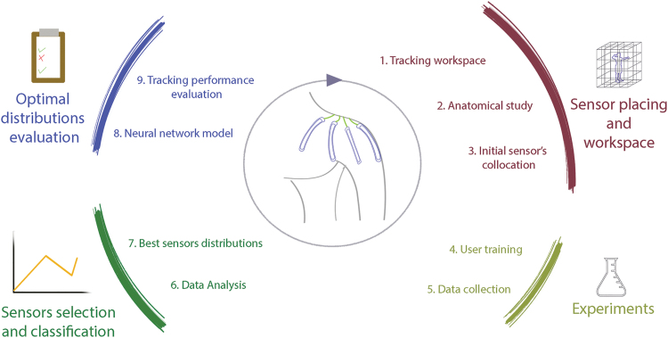
An iterative method has been followed to find the optimal sensor configurations. This method can be disclosed in four main blocks (Fig. 1) as follows: the first is focused on the tracking workspace and adequate placing of the sensors; the second one covers experimentation; and the third deals with the classification and selection of the most relevant sensors, whereas the last step evaluates optimal sensors' distributions. A proper sensor configuration can be found after several iterations.
FIG. 1.
Methodology applied to obtain optimal sensor distributions for measuring shoulder's multiaxial motion. Color images are available online.
Anatomical considerations and workspace of the shoulder
The initial distribution of the sensors mainly depends on the articulation's anatomy and mobility. The shoulder is a kinematically complex articulation constituted by four joints38: sternoclavicular, acromioclavicular, scapulothoracic, and glenohumeral. Through decades, various clinical studies have approached a virtual reference system that simplifies its complexity,39 rising the 6-DoF model of the shoulder as one of the most extensively applied simplifications. This approach provides a reliable inflexion point between simplicity and accuracy as it fits the glenohumeral and sternoclavicular motion schemes, by considering three rotations and three translations. Detailed information about its kinematic representation has been recently surveyed by Krishnan et al.40 In addition, several authors agree that only a subset of the complete range of motion of the shoulder is used in daily-living tasks like placing objects in shelves, combing hair, eating, or washing.41–43
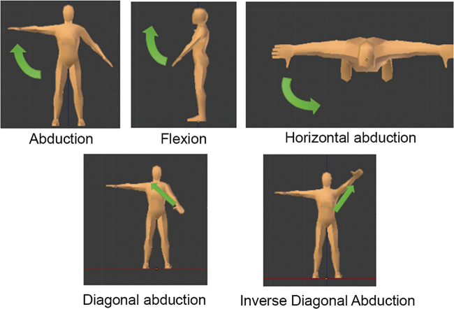
The conducted study considers the workspace defined by the gestures in Table 1. The three first movements in the table can be described as single rotations of the 6-DoF model of the shoulder, whereas the remaining two gestures combine different motions of the articulation. A representation of these five gestures is shown in Figure 2. These gestures also define the movements that subjects performed for data acquisition.
Table 1.
Description of the Gestures That Define the Workspace Considered Along with the Notation Used to Refer Them
| Gesture notation | Description |
|---|---|
| Abduction | Abduction/adduction of the shoulder until the arm reaches a 120° inclination |
| Flexion | Flexion/extension of the shoulder from 0° to 120° |
| Horizontal abduction | Horizontal displacement of the arm at 90° flexion, hand crosses sagittal plane till shoulder reaches a 30° displacement |
| Closing drill | Swing drill motion of the shoulder from 0° to 120° |
| Opening drill | Same swing drill motion than closing drill but starting with a flexion of 120° |
FIG. 2.
Gestures that define the workspace to monitor with the sensory system developed. The movements' order in Table 1 matches the figures from left to right, top to bottom. Color images are available online.
Description of the tests
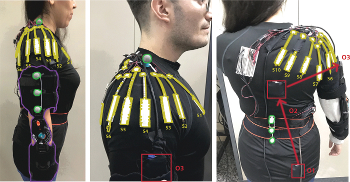
To assure the reproducibility and consistency of the data collected, the subjects are asked to perform three series of five repetitions of the movements (Table 1) with a resting period of 60 s between series, each gesture taking three seconds to be performed. In addition, a commercial medical orthosis (purple mark in Fig. 3a) is used to immobilize the elbow of the participants so as to control its influence over shoulder motion. Before the start of the tests, subjects practice all movements to become comfortable with the gestures and the speed requirements (6 s for each gesture repetition). In case of failure, the test is repeated after the participant has rested and practiced the gestures. Test guidance is provided by visual feedback about the gesture to perform, amount of repetitions, and motion speed.
FIG. 3.
Tracking systems and orthesis used in the experiments. The orthesis blocking the elbow is marked in purple on the left. Resistive sensors with guidance elements are highlighted in yellow. OptiTrack markers are denoted with green circles, whereas red rectangles mark the IMUs embedded in fabric. IMUs, inertial measurement units. Color images are available online.
Subjects' information
Ten healthy subjects with different constitutions and gender (seven male and three female) have participated in the experiments. They were properly informed and signed the corresponding consent forms to carry out the experiment according to the Universidad Politécnica de Madrid (UPM) ethical rules. The participants did not notify any injury, lesion, or health problem that could compromise either their health during the tests or the consistency of the results. Table 2 groups the anatomical data collected from the subjects with a goniometer. These mobility results prove that the system presented does not obstruct the mobility of the user.
Table 2.
Anatomical and Constitution Information of the Subjects
| R.O.M of the subject |
R.O.M wearing the sensorial system |
Weight (Kg) | Height (mm) | Age | |||||
|---|---|---|---|---|---|---|---|---|---|
| Shoulder flexion | Shoulder extension | Shoulder abduction | Shoulder flexion | Shoulder extension | Shoulder abduction | ||||
| 1 | 172 | −40 | 132 | 170 | −45 | 130 | 82 | 187 | 23 |
| 2 | 140 | −25 | 136 | 146 | −26 | 141 | 85 | 172 | 26 |
| 3 | 155 | −45 | 138 | 149 | −41 | 134 | 71 | 169 | 29 |
| 4 | 124 | −32 | 136 | 121 | −27 | 135 | 100 | 180 | 23 |
| 5 | 163 | −68 | 173 | 152 | −63 | 167 | 90 | 183 | 25 |
| 6 | 169 | −76 | 174 | 173 | −78 | 178 | 80 | 180 | 22 |
| 7 | 162 | −52 | 170 | 164 | −57 | 171 | 83 | 180 | 23 |
| 8 | 166 | −70 | 170 | 160 | −74 | 169 | 72 | 168 | 26 |
| 9 | 178 | −60 | 172 | 179 | −68 | 173 | 81 | 181 | 27 |
| 10 | 168 | −44 | 177 | 174 | −48 | 177 | 52 | 160 | 28 |
Data are expressed in degrees, kg, mm, and years. Mobility data have been acquired by a goniometer.
R.O.M, range of motion.
Description and design of the systems monitoring the shoulder and setup
Assuring an adequate initial distribution of the sensors over the shoulder allows easing the subsequent study and guaranteeing the consistency of the results. Three independent sensory systems are attached to a handmade sensorized shoulder suit (highlighted in Fig. 3) to analyze the performance of different configurations of flexible resistive sensors.
Flexible resistive sensor network
Ten flexible resistive sensors manufactured by Spectra Symbol44 are attached to a shoulder suit using plastic brackets. The shoulder suit is a compressive seamless shirt with three-dimensional printed sewn fixations for the sensors. This construction reduces obstructions, lateral displacements, and erratic folding. Detailed description of this hardware is provided in subsection Hardware developed for the proper monitoring of the shoulder motion using resistive sensors.
The criterion selected for defining the initial location of the sensors consists of identifying the major muscles involved in the motion of the shoulder and the skin areas that deform the most during movements. Three muscle actions are involved in the shoulder motion: force application, support, and stabilization. The muscles exerting force to displace the arm are the ones experiencing higher changes in its volume and section area.45 Consequently, these provide the most relevant information when measuring skin deformation or superficial changes. Trapezius muscle (the area over the supraspinatus), infraspinatus, deltoid muscle, and heads of the pectoralis, next to the deltopectoral triangle, are selected as the shoulder interest zones for this study. Table 3 refers to the exact position of these sensors, whereas Figure 3 illustrates the distribution of the sensors over a participant's shoulder.
Table 3.
Initial Position of the Resistive Flexible Sensors on the Shoulder Suit
| Sensor number | Position |
|---|---|
| S1 | Placed over the pectoralis heads. |
| S2 | Placed over the anterior deltoids. |
| S3 | Placed between the middle and anterior deltoids. |
| S4 | Placed over the middle deltoid muscle. |
| S5 | Placed between the posterior deltoid and middle deltoid. |
| S6 | Placed over the posterior deltoid. |
| S7 | Placed between the posterior deltoid and teres. |
| S8 | Placed over the trapezius, next to the acromion. |
| S9 | Placed over the trapezius and minor rhomboid. |
| S10 | Placed over the trapezius and major rhomboid. |
It must be noted that sensors are placed both over the middle segment of each muscle and in-between muscles. This approach aims to discover hidden patterns in skin deformation that allow reducing the number of sensors required: all shoulder muscles take part in arm positioning but in a different percentage depending on the gesture. In addition, this redundant collocation allows evaluating the impact on performance of misalignment between users.
OptiTrack (©2015 Natural Point, Inc., DBA OptiTrack)
This marker-based visual tracking system acts as ground truth to define the shoulder pose.46 OptiTrack has been used for calibrating the IMUs and resistive sensors since it provides submillimeter accuracy for the selected configuration of trackers. This configuration is based on seven markers that have been located according to BioMech marker-set protocol.47 As Figure 3 illustrates, the upper arm marker has been modified by moving it toward the lateral part of the arm. Two extra markers have also been added to the arm. These modifications improve tracking and reduce occlusion when using a four-camera setup at 240 Hz. The final arrangement of markers is as follows: three markers defining a rigid body in the humerus, one marker over the acromion, and the remaining three defining a rigid body in the lumbar part of the vertebral column.
IMU-based relative-positioning system
A drift-free IMU-based system estimates the shoulder motion in relation to the trunk location. It consists of three serially-placed IMUs as shown in the middle and right pictures of Figure 3. This complementary tracking system will be compared with the sensorized shoulder suit to evaluate its performance. Further details about the integration of this system are provided in Appendix A1.
Hardware developed for the proper monitoring of the shoulder motion using resistive sensors
Noise, sliding phenomena, misalignment between users, and other sort of textile-related events can highly impact the performance of cloth-wearable sensing systems. This subsection covers the three major drawbacks found during prototyping (textile influence, sensor calibration, and motion perturbances affecting resistive sensors), as well as the design particularities adopted to overcome them.
Textile influence
Materials, thickness, and seams in the fabric can have a significant influence on sensor performance. A preliminary prototype has been made to evaluate this effect. The design has 10 sensors evenly sewn to the inner and outer side of a commercial shoulder pad for sportive usage. The following three major conclusions are reached out of this experiment: textile compression affects sensors' measurement; seams and fabric thickness can create folds and air bags that alter sensor's response; and body shape differences can provoke discrepancies between both users and antagonistic sensors. Further detail about these statements can be found in Appendix A2.
The shoulder-suit presented in this article uses an elastic slightly compressive textile to reduce as much as possible these effects. The cloth is 0.85-mm thick, and seams have been moved off Deltoid surroundings to prevent undesired creases. In addition, two suit sizes (European M and S sizes) are available to improve adaptation to different arm constitutions.
Resistive sensors' behavior
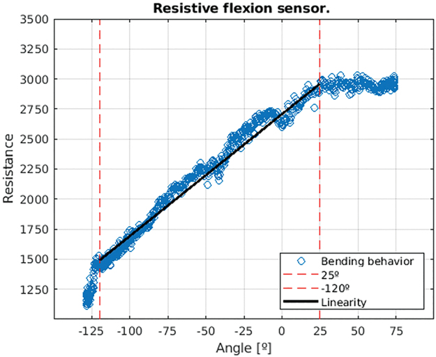
Flexible resistive sensors operate unidirectionally, meaning that they work only in one bending direction. Sensor's response, shown in Figure 4, has been obtained in isolated tests using a digital goniometer as ground truth. This chart describes the resistance value of a sensor when flexed from −135° to 75° and backwards.
FIG. 4.
Response of a flexible resistive sensor in a flexion cycle from −135° to 75°. Color images are available online.
The sensor has a central linear zone delimited by −120° and 25°, marked with red lines in Figure 4. It should also be noted that there is no visible hysteresis and that positive bendings saturate the output at 30°. Consequently, the system presented operates in the linear zone from −100° to 20°.
Sensor's guidance and complementary elements
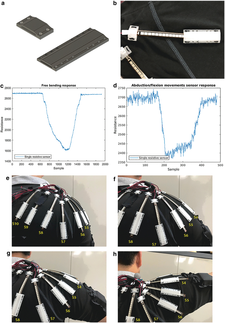
Previous studies with flexible resistive sensors report issues regarding stretching and sensors' deformation34 in other directions than the one considered. To avoid them, guidance and fixation elements for the resistive sensors have been designed. Figure 5 describes the mounting and sensor motion during experiments. The fastenings, in Figure 5a, consist of two pieces: the small piece fixes one end of the sensor to the upper part of the muscle, whereas the second one guides the sensor during motion. This larger piece is placed down the middle part of the muscle, depending on the deformation distance to measure. The assembling is shown in Figure 5b.
FIG. 5.
Detailed description of guidance and fixation pieces for flexible resistive sensors: (a) CAD model of both pieces. (b) Mounting of a sensor in the fabric. (c) Unmounted sensor response. (d) Response of a sensor when assembled with the pieces. (e–h) Motion of the sensors when worn and the user performs shoulder abduction. Color images are available online.
This design slightly alters the sensor's response by increasing its noise, see Figure 5c and d. In contrast, the mounting makes the sensor invulnerable to screw motion, stretching, and other artifacts noted by previous work with resistive sensors, as Figure 5e to h illustrate.
In such a manner, the shoulder suit presented uses a demi-elastic fabric with guidance and supporting elements that protect resistive sensors from undesired artifacts. Its seams have been placed to avoid creases in shoulder surroundings that could hamper measurements.
Results
The initial sensing distribution places sensors over each major muscle, as well as in between muscles. This collocation can eventually lead to sensory dimensionality reduction by discovering hidden data patterns. However, this correlation can also hinder NN generalization. Characterization and processing methods applied to the data to avoid these issues are presented through this section. Then, the performance and applicability of different NN models are assessed.
Characterization of the sensorial configuration in the shoulder suit by PCA
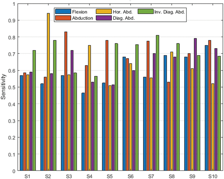
PCA techniques are applied to the sensor data obtained in the experiments. Figure 6 shows the PCA application results for the data collected by the 10 flexible sensors alongside the sensitivity of the 10 sensors to the 5 gestures in Table 1.
FIG. 6.
Sensitivity of each resistive flexible sensor to the motions described in Table 1. Color images are available online.
According to Figure 6, antagonist sensors have a similar behavior. However, the anatomical differences between the anterior and posterior muscles involved in the shoulder motion provoke sensitivity discrepancies in mirrored sensors, like the response from S2 and S6 to flexion and abduction. Repositioning the sensors can also provoke significant changes in its sensitivity, such as it occurs with sensors S9 and S10 or S4 and S5. Consequently, the correlation between sensors must be considered when choosing the most relevant ones and their optimal positioning.
Table 4 expresses the PCA results plotted in Figure 6 with the contribution of each sensor to the principal components of the information variability; in other words, the sensitivity of each sensor to all the motions performed by the participants in the experiment. Under a conservative approach, dimensionality can be gently reduced to seven sensors preserving 95% of the total data variance and to five sensors with 90% of the data variance.
Table 4.
Principal Component Analysis Results of the Data Gathered by the Initial Sensor Distribution During the Tests
| Sensor | PCA (%) | Accumulated |
|---|---|---|
| S2 | 37.97 | 37.97 |
| S3 | 23.02 | 60.99 |
| S7 | 12.55 | 73.54 |
| S8 | 8.78 | 82.32 |
| S5 | 6.64 | 88.96 |
| S10 | 3.69 | 92.65 |
| S4 | 2.19 | 94.84 |
| S9 | 1.99 | 96.83 |
| S6 | 1.74 | 98.57 |
| S1 | 1.43 | 100 |
The sensors in this table are ordered according to its contribution to data variance. The second column, PCA, shows the percentage of data variance related to each sensor. The third column shows the data variance accumulated by current and preceding rows.
PCA, principal component analysis.
To further reduce the sensor network, instead of choosing the sensors that contribute the most to the total data variance, the ones providing the highest sensitivity for each gesture will be selected. To this end, three zones are defined in the shoulder adjoining areas. Each of these zones represents a major muscle: Trapezius, Deltoid (posterior and middle segment), and Pectoral. The Pectoral contribution to shoulder motion is partial and it mostly coincides with the Anterior Deltoid involvement in flexion motions; thus, sensors over both muscles are assigned to the same area. This approach ensures that a network of three sensors containing 54% of PCA is sensitive to every major muscle deformation. This reduced sensor network is formed by sensors S2, S7, and S10.
Subsection Performance results of the flexible resistive sensor networks evaluates the shoulder pose estimation of the three sensor configurations obtained:
Seven sensors with 95% data variance (S2, S3, S7, S8, S5, S10, S4)
Five sensors with 90% data variance (S2, S3, S7, S8, S5)
The three sensors representing the three major muscles (S2, S7, S10)
Sensor data processing
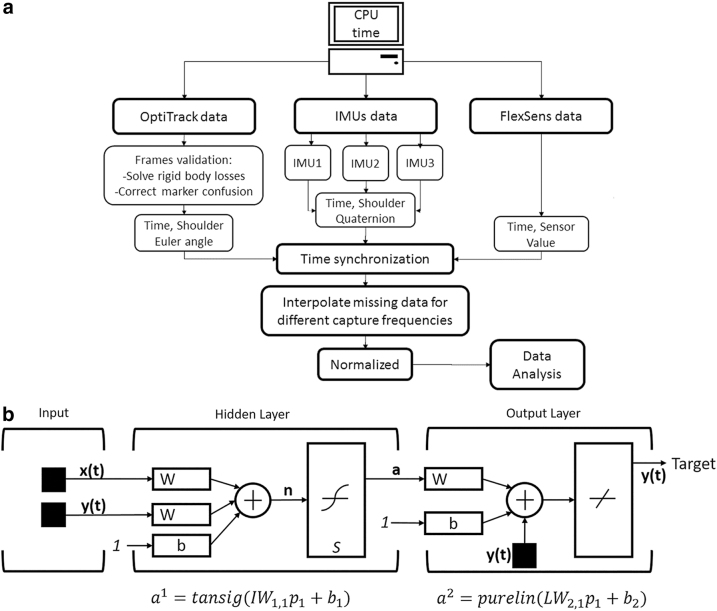
Figure 7a outlines the different stages of data processing. First, before the start of the experiment, a synchronization signal with the initial timestamp reference systems is sent to the three measurement systems. The operating frequency of the flexible resistive sensors is set to match Optitrack's one, 400Hz. The OptiTrack, acting as ground truth in the experiments, cannot be set to match this refresh rate, so the data are transformed afterward by applying cubic interpolation splines.
FIG. 7.
(a) Data processing and synchronization stages applied to feed the NNs and evaluate the performance of the system. (b) Structure of a time series NN. NN, neural network.
In addition, each frame of the OptiTrack recording is checked off-line since several marker-detection errors can appear during the tests, mostly when a rigid body overlaps with another one. To troubleshoot it, the off-line tool in OptiTrack software is used to define the trajectories of the overlapped markers. Finally, the data are normalized to avoid feature-scaling related errors.
Models for motion-pattern extraction
The data collected in the experiments are applied to NN models for shoulder pose estimation. These models allow evaluating the tracking performance of different flexible resistive sensor configurations in comparison with an IMU-based system, as well as the performance improvement achieved when the IMUs are combined with flexible resistive sensors.
All neural models in Tables 5 and 6 are implemented in the Matlab Machine Learning Toolbox 2018b. This toolbox trains a neural structure consisting of two feed-forward subnetworks in open loop. The particularity of this neural structure, in Figure 7b, is that its open-loop characteristic allows feeding the prediction and the real input to the second subnetwork. Therefore, the first subnetwork predicts the next value of a time series (TS) considering its current value and several past values, denoted as delay (d), whereas the second subnetwork adjusts the output of the model to fit different behaviors. Depending on the loss and activation functions applied on each layer and the type of input, the model can be used to predict TS values or to classify the input. Models in Table 5, denoted as classifier (C), modify the second subnetwork to obtain a sigmoid approximation that classifies the gesture (Table 1) being performed, whereas the ones in Table 6, denoted as TS, use the standard model of the toolbox to estimate the shoulder pose.
Table 5.
Models of Neural Networka for Gesture Classification (20 Hidden Layers)
| NN model | Input | Target |
|---|---|---|
| 1C | All flex. sensors | Gesture |
| 2C | Flex. sensors 2, 3, 4, 5, 7, 8, 10 | Gesture |
| 3C | Flex. sensors 2, 3, 5, 7, 8 | Gesture |
| 4C | Flex. sensors 2, 7, 10 | Gesture |
| 5C | IMU | Gesture |
The classifier applied is a TS modified to classify the input.
C, classifier; IMU, inertial measurement unit; NN, neural network; TS, time series.
Table 6.
Models of Neural Network Trained for Motion Prediction (20 Hidden Layers)
| NN model | Input | Target |
|---|---|---|
| 1TS | All flex. sensors | OptiTrack |
| 2TS | IMU | OptiTrack |
| 3TS | Flex. sensors 2, 3, 4, 5, 7, 8, 10 | OptiTrack |
| 4TS | Flex. sensors 2, 3, 5, 7, 8 | OptiTrack |
| 5TS | Flex. sensors 2, 7, 10 | OptiTrack |
| 6TS | All flex. sensors + IMU | OptiTrack |
| 7TS | Flex. sensors 2, 3, 4, 5, 7, 8, 10 + IMU | OptiTrack |
| 8TS | Flex. sensors 2, 3, 5, 7, 8 + IMU | OptiTrack |
| 9TS | Flex. sensors 2, 7, 10 + IMU | OptiTrack |
The models in Tables 5 and 6 have 20 hidden layers and input the current sample alongside the six previous measurements. Their training is done with 70% of the data collected during the tests, while the remaining 30% is evenly applied in the validation and test stages. All the gathered data are rearranged in batches by grouping one repetition of each gesture, resulting in 15 batches for each participant. Then, the batches are shuffled and randomly selected to match the 70-15-15 distribution for the training, cross validation, and test stages.
Performance results of the flexible resistive sensor networks
Tables 7 and 8 gather the performance results of the neural models designed to both classify the gesture and estimate the shoulder pose. In these models, four different distributions of flexible resistive sensors are evaluated individually and in combination with a drift-free IMU system.
Table 7.
Performance of the Neural Networks in Table 5 for Classifying the Gesture Performed by the Subject
| NN model | No. input | MSE |
|---|---|---|
| 1C | 10 | 1.32E-05 |
| 2C | 7 | 3.04E-07 |
| 3C | 5 | 2.30E-06 |
| 4C | 3 | 2.88E-04 |
| 5C | IMU | 1.68E-05 |
Labels are in accordance with Table 1.
MSE, mean squared error.
Table 8.
Performance of the Neural Networks in Table 6 for Tracking the Shoulder Motion in the Workspace Defined in Table 1
| NN model | Sensor as input (flex sensors + IMU) | MSE |
|---|---|---|
| 6TS | 10 + IMU | 2.35E-07 |
| 1TS | 10 | 2.50E-06 |
| 4TS | 5 | 2.72E-06 |
| 9TS | 3 + IMU | 6.53E-06 |
| 3TS | 7 | 1.19E-05 |
| 7TS | 7 + IMU | 1.79E-05 |
| 8TS | 5 + IMU | 5.95E-05 |
| 2TS | IMU | 2.74E-04 |
| 5TS | 3 | 1.31E-03 |
According to Table 7, the mean squared error (MSE) in gesture classification is lower than 0.001 in all cases, pointing out that all systems are adequate for multiclass gesture classification. In this case, the seven-sensor distribution delivers the highest accuracy, closely followed by the five-sensor distribution. The initial distribution of sensors almost matches the accuracy of the IMU system; meanwhile, the three-sensor configuration is the worst-rated one. However, the objective of the system is not gesture classification but shoulder pose estimation whose results can be found in Table 8.
The first significant outcome regarding shoulder pose estimation is that NN application boosts up the IMU performance, which goes from 0.99E-02 (no NN applied) to 2.74E-04 (model 2TS) compared with OptiTrack. Combining this IMU with the 10 flexible resistive sensors delivers the best MSE result (6TS). In contrast, the 10-sensor configuration alone (model 1TS) increases the MSE to 2.50E-06, but it still beats the neurally enhanced IMU system.
Another remarkable fact is that PCA allows reaching a compromise between the measuring accuracy and the number of sensors. Models 4TS and 3TS, which, respectively, only use five and seven flexible resistive sensors, reduce the number of sensors without significantly affecting the MSE. Two aspects of these models and its performance must be highlighted in this regard. First, the five-sensor network (4TS) delivers a lower MSE than the seven-sensor one (3TS). Second, even though both models use the same sensors, the seven ones also include S10 and S4, which proves that adding new sensors to a distribution can increase correlation, hence negatively affect pose estimation.
Conversely, further reducing the number of sensors to three drastically increases the MSE in three orders of magnitude, up to 1.31E-03.
The combination of the IMUs with flexible resistive sensors only improves performance in two cases: the 10-sensor (model 1TS) and three-sensor distributions (model 5TS). The former delivers the best results of the study, whereas the latter boosts the performance of the sole flexible resistive sensor network in three orders of magnitude. This result is to be expected since the dimensionality of the configuration with three sensors is so reduced that any feature enhancement will raise its performance.
Discussion
This study describes the procedure to obtain a distribution of flexible resistive sensors for shoulder motion tracking, consisting on the design of a shoulder suit embedding 10 flexible sensors, an IMU-based measuring system, and seven OptiTrack markers. The shoulder suit can be defined as completely wearable according to the mobility results presented in Table 1.
Two different NN models are applied to the system to successfully classify user gestures and estimate the shoulder pose. During the design of these models, different hidden layer configurations are evaluated to guarantee absence of overfitting and underfitting. Several reasons justify using only a type of NN. It has proved to be more useful evaluating variants of the same model than testing different neural structures; applying different neural structures like long short-term memory or recurrent NNs can deliver better accuracy but it makes difficult determining which is the best distribution since other factors like epochs, optimizer, regression, and data representation will have to be considered.
During neural model design, a significant improvement in classification results is detected when including an additional label for classifying the natural pose of the subject (anatomical zero position of the user when the arm lies down parallel to the body). Another significant improvement will be including static gestures (in which random poses are maintained for a few seconds) and fast movements. The system has been evaluated with dynamic gestures at constant speed, meaning that consecutive samples of the shoulder pose are always different, except in the initial and final pose of the gesture. In addition, subjects require proper feedback, resting periods, and guidance through the experiments to avoid fatigue and mistakes that will invalidate the data. Using a visual marker-based system in a supervised environment, OptiTrack delivers a reliable ground truth to early detect and deal with these faults.
All systems individually show adequate performance for gesture recognition, which can be used as an input indicator for motion prediction in future prospect. Regarding shoulder pose estimation, Table 9 summarizes the most significant results of the four different flexible resistive sensor distributions, the drift-free IMU system, and their combination.
Table 9.
Sensory Systems Delivering the Best Results When Tracking the Shoulder Motion During the Experiments in the Workspace Defined by Table 1
| NN model | MSE | Max error Measured (in degrees) |
|---|---|---|
| 10-Resistive-flexible-sensor + IMU | 2.35E-07 | 0.08 |
| 5-Resistive-flexible-sensor network | 2.72E-06 | 0.156 |
| 3-Resistive-flexible-sensors + IMU | 1.85E-05 | 0.163 |
| IMU with TS NN | 2.74E-04 | 0.17 |
| 3-Resistive-flexible-sensor network | 1.31E-03 | 0.20 |
| IMU without NN | 0.99E-02 | 0.6 |
MSE is the results obtained from neural model tests.
The third column is the max difference in degrees between OptiTrack (Ground Truth) and the model output.
The proposed system exhibits a promising performance for exosuits and wearable applications since it matches the IMU-system results. This IMU system whose construction is detailed in Appendix A1 gathers the most common characteristics of IMUs used in exoskeletons of state of the art.
Although the four different distributions of flexible resistive sensors evaluated are suitable for shoulder motion tracking, there is a significant difference in performance. In such manner, those applications with crucial requirements in terms of sensing and actuation that will benefit from the best performance configuration, like telemanipulation in harsh environments, must use the 10-sensor configuration, in accordance with Table 9. Those applications with lesser accuracy requirements looking for cost reduction, like virtual reality for entertainment or serious gaming, must consider using the three- and five-sensor configurations. The seven-sensor configuration, on the other hand, must never be used, being always more convenient the five-sensor distribution.
The poor performance of the seven-sensor distribution proves that sensor addition is not always beneficial as it can increase data correlation in a way that biases the NN. This inference is strengthened by the results obtained when combining the flexible resistive distributions with the IMU system. Only the 10 sensors and the three-sensor distribution improve its performance when combined with the IMU system. In addition, these are the only two distributions obtained taking the major deformation directions into consideration since the others derive from direct PCA reduction. The previous statement can therefore be extended by asserting that sensor addition must preserve the principal components of the data variance to enhance the total performance of the system.
The number of sensors can be reduced likewise, provided that sensors' collocation preserves data principal components. Hidden muscle activation patterns can reveal in-between muscle positions whose combination is sensitive enough to all gestures. The three sensor network uses two sensors (S7 and S10) placed between two muscles.
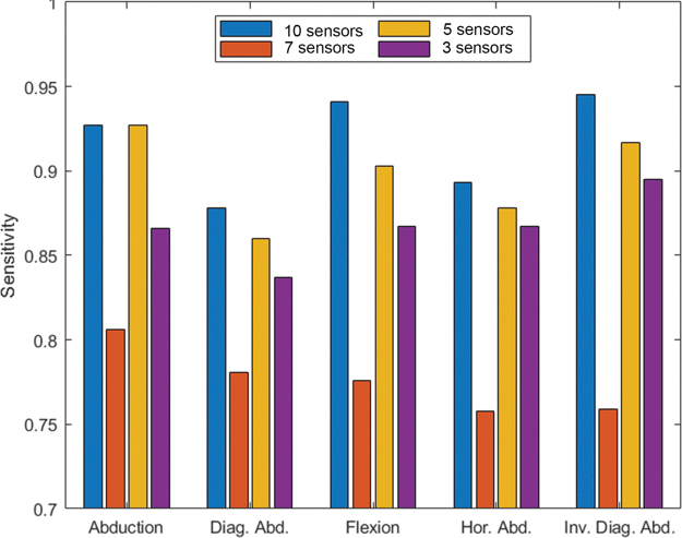
In terms of precision, it can be stated that a proper resistive sensor configuration with five or more straps delivers better performance (error <0.15°) than a tracking system based on IMUs (error ∼0.6°). As Table 9 exposes, an accuracy loss is suffered when further reducing the number of flexible resistive sensors used. Nonetheless, a precision around 0.2° can still be reached with three sensors by adequately approaching in-between muscle collocation and muscle activation patterns. In addition, it must be noted that varying the number of sensors does not only have an impact over precision but also over sensitivity. According to Figure 8, as the number of sensors in the shoulder suit increases, so does the gesture sensitivity. This statement is only valid when sensors are properly placed; sensitivity dramatically decreases otherwise, just like the seven-sensor results show. Networks with 10 and 5 sensors have a gesture sensitivity ≥0.85, being predominant abduction and flexion directions along with their composition in inverse diagonal abduction motions. In contrast, the three-sensor network delivers equal sensitivity to the three glenohumeral motions (0.87).
FIG. 8.
Sensitivity to each gesture of the four collocations of resistive sensors discussed. Color images are available online.
In addition, all systems exhibit less sensitivity to diagonal abduction, which contrasts with the detection of its antagonistic motion: inverse diagonal abduction. Two major causes can be found in this regard. On the one hand, due to space availability, there are more sensors distributed over the posterior muscles. On the other hand, posterior muscles (Deltoid and Trapezius) suffer a higher surface deformation than anterior ones when positioning the elbow. This second statement is reinforced by the unidirectional operation of the resistive sensors, which prevents using posterior sensors to detect diagonal abduction since their measurement goes out of the linear limits presented in “Resistive sensors' behavior” section when diagonal abduction is performed.
To conclude, it can also be stated that models do a proper generalization between subjects; thus, body shape differences can be reduced by compliant sewing, fabric selection, and high-dimensionality mapping.
Conclusions
Exosuits, just as any other soft robotic application, require from novel sensing and actuation systems. Relevant advances have been achieved in soft actuators with compliant mechanisms and variable stiffness during the last years. Sensing systems must also be improved and adapted to properly measure the human body motion. The conducted study presents an alternative system based on flexible resistive sensors to measure the multiaxial shoulder motion. This system is completely wearable, and it does not restrict the mobility of the user. In addition, it is affordable and can be easily embedded in fabrics. The system also counts with a fast and simple calibration procedure consisting of setting user's zero or rest position.
Relevant conclusions can be extracted from this work. First, the study of the anatomical function of the joints and muscles of interest must be cautiously addressed to determine the initial number of sensors and their placement according to the directions of the main deformations. The fixation of the sensors must provide guidance for their linear deformation in these directions of interest; otherwise, the fabric will produce artifacts in the measurements. Second, PCA techniques have proven adequate to reduce the number of flexible-resistive sensors in the shoulder suit. Third, a set of three flexible resistive sensors, being properly located, have proven to be good enough to beat the performance of a set of three IMUs without posterior neural network processing. This three-sensor distribution almost matches the performance of a neurally-enhanced IMU system. Better performance can be achieved using more complex configurations with 10 and 5 sensors. Adequately placing sensors between muscles can favor model generalization and network sensitivity to different gestures.
According to our results, a network with five or more resistive sensors can successfully follow OptiTrack positioning with a precision error smaller than 1E-02. The proposed wearable system is a good alternative to depth cameras, elastomer-based solutions, and IMUs.
This soft sensing solution can be exploited in different applications that require human body tracking in open spaces. Three efficient collocations of flexible resistive sensors have been presented in this regard, depending on performance and budget requirements. Authors are applying this textile-wearable solution as shoulder motion tracking feedback for the control of an upper-limb exosuit named ExoFlex. In addition, new gestures like fast movements and static poses will be eventually included in the experiments.
Appendix
APPENDIX A1. Implementation of an Inertial Measurement Unit-Based System for Relative Positioning
An inertial measurement unit (IMU)-based relative positioning system has also been developed to monitor the shoulder motion during the experiments. This complementary system aims to gather the most representative characteristics of IMUs for exoskeletons. In this regard, some authors, like Ahmad et al.A1 and Duivenvoorden et al.,A2 state in their reviews that the working principles and integrated technology must prevail over the refresh rate when selecting an IMU. These reviews also point out that the most widely used IMUs are those with 6 and 9-axis constructions and refresh rates between 5 and 50 Hz. However, most demanding applications, like robotic navigation or exoskeletons, can require ratios above 200 Hz to avoid drift-related errors. Serving as an example, Wang et al.A3 demonstrate that 400 Hz communication with 100 Hz sampling frequency is enough to track human motion, despite some designs using devices with sampling rates up to 1 kHz.A4
The system presented in the article applies a 9-axis IMU with a Kalman processing stage on board. The selected model is the LPMS-URS2 with gyroscope, accelerometer, and magnetometer, manufactured by LP-Research.A5 This sensor delivers filtered data as output at frequencies up to 400 Hz with a resolution of 0.01°. Three LMPS-URS2 sensors are located over the arm and back of the user to create a drift-avoidance serially-connected chain as Figure 3 illustrates. The base of the system is located over the gluteus, the second IMU lies over thoracic vertebral column, and the last one is placed over the arm. The shoulder pose can be estimated by obtaining the relative position of the IMU over the arm.
APPENDIX A2. Evaluation of Textile Influence in Sensor Collocation
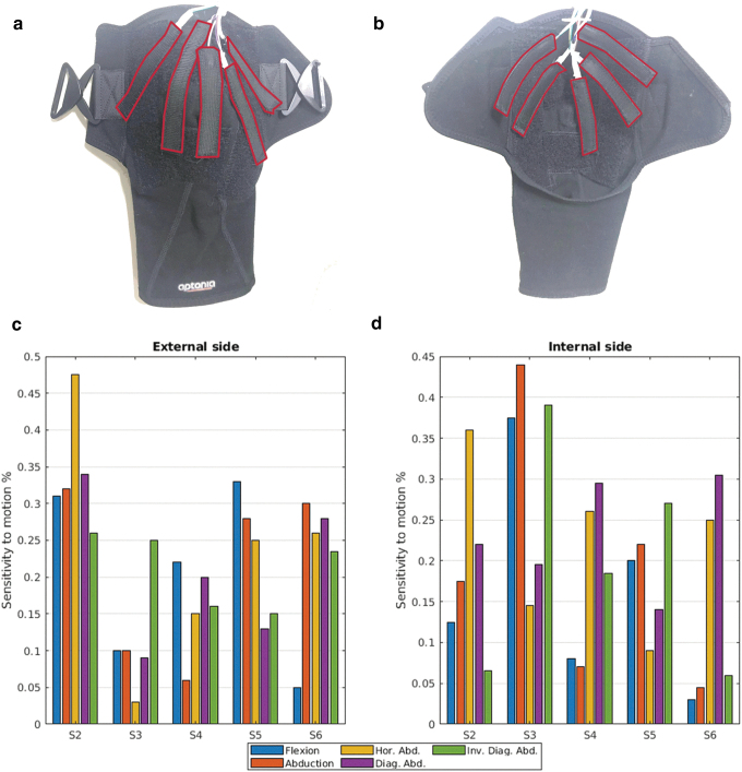
The design of the shoulder suit presented in this document is based on preliminary experiments conducted to evaluate textile influence. To this end, 10 flexible resistive sensors are evenly distributed in the inner and outer side of a sportive commercial shoulder pad made of 1.92-mm thick compressive fabric. The sensors are embedded in tailor-made sheaths and attached to Velcro bands in shoulder pad positions S2, S3, S4, S5, and S6 of Table 3. Appendix Figure A1a and b describes the position of these straps on both sides of the shoulder pad.
The methodology described in Materials and Methods section has been applied to evaluate this shoulder pad too, with the same participants referred in Table 2. The principal component analysis and sensitivity results obtained for this shoulder pad are in Appendix Figure A1c and d.
From these results, a pronounced sensitivity difference is observed between internal and external placing of sensors. In some cases, such as S3, textile compression on the inner side improves sensitivity by better adhesion of the sensor to the skin. There are also cases in which sensors deliver an unexpected response. As an example, the sensor located over the Middle Deltoid, S4, is almost insensitive to abduction movements, which can be caused either by textile influence or body shape differences. In other cases, like S5 and S6, sensing response does not match between inner and outer placing. Cloth folding and air bags observed around this location during the experiments may be causing these alterations.
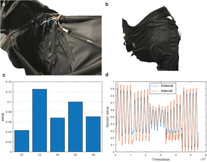
This sort of textile perturbations can be overcome using thin fabrics and moving the seams off the Deltoid surroundings. This inference has been evaluated by designing a shoulder suit made of 0.85-mm thick elastic fabric with 10 sensors evenly sewn to both sides of the cloth (Appendix Fig. A2a, b). The measurement discrepancies between sensors on the inner and outer side are shown in Appendix Figure A2c. It can be stated that there is a gain difference in performance between internal and external placing of the sensors but both sides are compliant (Appendix Fig. A2d). In consequence, aiming to improve comfort and avoid skin-pressure related issues, the final design of the shoulder suit presented in this document places sensors on the external side of the fabric. In addition, guidance and fixation elements have been included to prevent stretching and nonlinearities as discussed in Materials and Methods section. Furthermore, two suit sizes (European M and S sizes) are available to improve adaptation to different arm constitutions.
APPENDIX FIG. A1. Design and results of the thick shoulder pad described in Appendix A2 to infer textile influence on performance. (a) External placement and attachment of the sensors. (b) Internal placement and attachment of the sensors. (c) Sensitivity to each gesture of the external sensors. (d) Sensitivity to each gesture of the internal sensors. Color images are available online.
APPENDIX FIG. A2. Design and results of the second shoulder pad with thin fabric used in Appendix A2 to infer textile influence on performance. (a) Inner placement and sewing of the sensors. (b) Sewing and placing of external sensors, coincident with internal collocation. (c) RMSE difference for each sensor when placed internally versus externally. (d) Curve for inner and outer sensor over anterior deltoid. RMSE, root mean-squared error. Color images are available online.
Appendix References
- A1.Ahmad N, Ghazilla RA, Khairi NM, et al. Reviews on various inertial measurement unit (IMU) sensor applications. Int J Signal Process Syst 2013;1:256–262 [Google Scholar]
- A2.Duivenvoorden A, Lee K, Raison M, et al. Sensor fusion in upper limb area networks: a survey. In: Global Information Infrastructure and Networking Symposium (GIIS); St. Pierre, France, pp. 56–63, 2017 [Google Scholar]
- A3..Wang J, Li X, Huang TH, et al. Comfort-centered design of a lightweight and backdrivable knee exoskeleton. IEEE Robot Autom Lett 2018;3:4265–4272 [Google Scholar]
- A4.Lessard S, Pansodtee P, Robbins A, et al. A soft exosuit for flexible upper- extremity rehabilitation. IEEE Trans Neural Syst Rehabil Eng 2018;26:1604–1617 [DOI] [PubMed] [Google Scholar]
- A5.Life Performance Research. LPMS-URS2: 9-axis inertial measurement unit (IMU)/AHRS with USB and RS232 connectivity. https://lp-research.com/lpms-urs2/ (accessed December16, 2019)
Author Disclosure Statement
No competing financial interests exist.
Funding Information
This work has been partially supported by the project “ExoFlex: Exoesqueleto ligero para la generación de fuerzas en las extremidades superiores aplicado a tareas de rehabilitación,” under DPI-2015-68842-R grant, funded by the Spanish ‘Ministerio de Economía, Industria y Competitividad’, and “LUXBIT: Lightweight Upper limbs eXosuit for BImanual Task Enhancement/Exoesqueleto ligero del tren superior para ayuda a tareas bimanuales” under RTI2018-094346-B-I00 grant, funded by the Spanish ‘Ministerio de Ciencia, Innovación y Universidades’.
References
- 1. Fei Y, Wang J, Pang W. A novel fabric-based versatile and stiffness-tunable soft gripper integrating soft pneumatic fingers and wrist. Soft Robot 2019;6:1–20 [DOI] [PubMed] [Google Scholar]
- 2. Ward-Cherrier B, Pestell N, Cramphorn L, et al. The TacTip family: soft optical tactile sensors with 3D-printed biomimetic morphologies. Soft Robot 2018;5:216–227 [DOI] [PMC free article] [PubMed] [Google Scholar]
- 3. Nguyen PH, Sparks C, Nuthi SG, et al. Soft poly-limbs: toward a new paradigm of mobile manipulation for daily living tasks. Soft Robot 2019;6:38–53 [DOI] [PubMed] [Google Scholar]
- 4. Van der Helm FC. Analysis of the kinematic and dynamic behavior of the shoulder mechanism. J Biomech 1994;27:527–550 [DOI] [PubMed] [Google Scholar]
- 5. Tomoaia G, Benea H, Miclea L. Computed study of shoulder dynamics Kinematics and dynamic analysis of shoulder movement. In: IEEE International Conference on Automation, Quality and Testing, Robotics; Cluj-Napoca, Romania, pp. 90–93, 2008 [Google Scholar]
- 6. Guizzo E, Goldstein H. The rise of the body bots [robotic exoskeletons]. IEEE Spectr 2005;42:50–56 [Google Scholar]
- 7. Sharma CA, Kumar AK, Prasad A, et al. Multifaceted bio-medical applications of exoskeleton: a review. In: 2nd International Conference on Inventive Systems and Control (ICISC); Coimbatore, India, pp. 11–15, 2018 [Google Scholar]
- 8. Allen S. New prostheses and orthoses step up their game: motorized knees, robotic hands, and exosuits mark advances in rehabilitation technology. IEEE Pulse 2016;7:6–11 [DOI] [PubMed] [Google Scholar]
- 9. Lessard S, Pansodtee P, Robbins A, et al. A soft exosuit for flexible upper- extremity rehabilitation. IEEE Trans Neural Syst Rehabil Eng 2018;26:1604–1617 [DOI] [PubMed] [Google Scholar]
- 10. Wang WW, Fu LC. Mirror therapy with an exoskeleton upper-limb robot based on IMU measurement system. In: IEEE International Symposium on Medical Measurements and Applications; Bari, Italy, pp. 370–375, 2011 [Google Scholar]
- 11. Bouvier B, Duprey S, Claudon L, et al. Upper limb kinematics using inertial and magnetic sensors: comparison of sensor-to-segment calibrations. Sensors 2015;15:18813–18833 [DOI] [PMC free article] [PubMed] [Google Scholar]
- 12. Santaera G, Luberto E, Serio A, et al. Low-cost, fast and accurate reconstruction of robotic and human postures via IMU measurements. In: IEEE International Conference on Robotics and Automation (ICRA); Seattle, WA, pp. 2728–2735, 2015 [Google Scholar]
- 13. Webster D, Celik O.. Experimental evaluation of Microsoft Kinect's accuracy and capture rate for stroke rehabilitation applications. In: IEEE Haptics Symposium, Houston, TX, 2014. DOI: 10.1109/HAPTICS.2014.6775498 [DOI] [Google Scholar]
- 14. Morrow MM, Lowndes B, Fortune E, et al. Validation of inertial measurement units for upper body kinematics. J Appl Biomech 2017;33:227–232 [DOI] [PMC free article] [PubMed] [Google Scholar]
- 15. Garimella R, Peeters T, Beyers K.. Capturing joint angles of the off-site human body. IEEE SENSORS, New Delhi, India, 2018. DOI: 10.1109/ICSENS.2018.8589711 [DOI] [Google Scholar]
- 16. Crema C, Depari A, Flammini A. Characterization of a wearable system for automatic supervision of fitness exercises. Measurement 2019;147:106810 [Google Scholar]
- 17. De Baets L, Van der Straaten R, Matheve T, et al. Shoulder assessment according to the international classification of functioning by means of inertial sensor technologies: a systematic review. Gait Posture 2017;57:278–294 [DOI] [PubMed] [Google Scholar]
- 18. Kiguchi K, Rahman MH, Sasaki M. Neuro-fuzzy based motion control of a robotic exoskeleton: considering end-effector force vectors. In: IEEE International Conference on Robotics and Automation; Orlando, FL, pp. 3146–3151, 2006 [Google Scholar]
- 19. Kiguchi K, Tanaka T, Fukuda T. Neuro-fuzzy control of a robotic exoskeleton with EMG signals. IEEE Trans Fuzzy Syst 2004;12:481–490 [Google Scholar]
- 20. Kiguchi K, Hayashi Y. An EMG-based control for an upper-limb power-assist exoskeleton robot. IEEE Trans Syst Man Cybern B Cybern 2012;42:1064–1071 [DOI] [PubMed] [Google Scholar]
- 21. Jang HY, Ji YH, Han JS, et al. Development and verification of upper extremities wearable robots to aid muscular strength with the optimization of link parameters. Int J Precis Eng Manuf 2015;16:2569–2575 [Google Scholar]
- 22. Del Rincón JM, Makris D, Uruñuela CO, et al. Tracking human position and lower body parts using Kalman and particle filters constrained by human biomechanics. IEEE Trans Syst Man Cybern B Cybern 2011;41:26–37 [DOI] [PubMed] [Google Scholar]
- 23. Rietzler M, Geiselhart F, Thomas J, et al. A generic toolkit for skeleton, marker and rigid-body tracking. In : Proceedings of the 8th ACM SIGCHI Symposium on Engineering Interactive Computing Systems, Brussels, Belgium, 2016. DOI: 10.1145/2933242.2933263 [DOI] [Google Scholar]
- 24. Jung Y, Bae J. Kinematic analysis of a 5-dof upper-limb exoskeleton with a tilted and vertically translating shoulder joint. IEEE ASME Trans Mechatron 2014;20:1428–1439 [Google Scholar]
- 25. Guevara DC, Vietri G, Prabakar M, et al. Robotic exoskeleton system controlled by kinect and haptic sensors for physical therapy. In: Southern Biomedical Engineering Conference 29th; Miami, FL, pp. 71–72, 2013 [Google Scholar]
- 26. Mousavi Hondori H, Khademi M. A review on technical and clinical impact of microsoft kinect on physical therapy and rehabilitation. J Med Eng 2014;2014:846514. [DOI] [PMC free article] [PubMed] [Google Scholar]
- 27. Aggarwal JK, Xia L. Human Activity recognition from 3D data: a review. Pattern Recognit Lett 2014;48:70–80 [Google Scholar]
- 28. Masdar A, Ibrahim BS, Hanafi D, et al. Knee joint angle measurement system using gyroscope and flex-sensors for rehabilitation. In: The 6th 2013 Biomedical Engineering International Conference; Amphur Muang, Thailand, pp. 1–4, 2013 [Google Scholar]
- 29. Copaci D, Cano E, Moreno L, et al. New design of a soft robotics wearable elbow exoskeleton based on shape memory alloy wire actuators. Appl Bionics Biomech 2017;2017:1605101. [DOI] [PMC free article] [PubMed] [Google Scholar]
- 30. Walmsley CP, Williams SA, Grisbrook T, et al. Measurement of upper limb range of motion using wearable sensors: a systematic review. Sports Med Open 2018;4:53. [DOI] [PMC free article] [PubMed] [Google Scholar]
- 31. Carbonaro N, Dalle Mura G, Lorussi F, et al. A Exploiting wearable goniometer technology for motion sensing gloves. IEEE J Biomed Health Inform 2014;18:1788–1795 [DOI] [PubMed] [Google Scholar]
- 32. Lorussi F, Rocchia W, Scilingo EP, et al. Wearable, redundant fabric-based sensor arrays for reconstruction of body segment posture. IEEE Sens J 2004;4:807–818 [Google Scholar]
- 33. Huang B, Li M, Mei T, et al. Wearable stretch sensors for motion measurement of the wrist joint based on dielectric elastomers. Sensors 2017;17:2708. [DOI] [PMC free article] [PubMed] [Google Scholar]
- 34. Tognetti A, Carbonaro N, Zupone G, et al. Characterization of a novel data glove based on textile integrated sensors. In: 2006 International Conference of the IEEE Engineering in Medicine and Biology Society, New York, NY, IEEE, Vol. 30, pp. 2510–2513, 2006 [DOI] [PubMed] [Google Scholar]
- 35. Cestari M, Sanz-Merodio D, Garcia E. Preliminary assessment of a compliant gait exoskeleton. Soft Robot 2017;4:135–146 [DOI] [PubMed] [Google Scholar]
- 36. Villoslada Á, Rivera C, Escudero N, et al. Hand exo-muscular system for assisting astronauts during extravehicular activities. Soft Robot 2019;6:21–37 [DOI] [PubMed] [Google Scholar]
- 37. Al-Fahaam H, Davis S, Nefti-Meziani S, et al. Novel soft bending actuator-based power augmentation hand exoskeleton controlled by human intention. Intell Serv Robot 2018;11:247–268 [Google Scholar]
- 38. Marieb EN, Hoehn K. The skeleton. In: Human Anatomy and Physiology, 9th edition. Boston, MA: Pearson Education, pp. 227–254, 2013 [Google Scholar]
- 39. Maurel W, Thalmann D. Human shoulder modeling including scapulo-thoracic constraint and joint sinus cones. Comput Graph 2000;24:203–216 [Google Scholar]
- 40. Krishnan R, Björsell N, Gutierrez-Farewik EM, et al. A survey of human shoulder functional kinematic representations. Med Biol Eng Comput 2019;57:339–367 [DOI] [PMC free article] [PubMed] [Google Scholar]
- 41. Magermans DJ, Chadwick EKJ, Veeger HEJ, et al. Requirements for upper extremity motions during activities of daily living. Clin Biomech 2005;20:591–599 [DOI] [PubMed] [Google Scholar]
- 42. Perry JC, Rosen J, Burns S. Upper-limb powered exoskeleton design. IEEE ASME Trans Mechatron 2007;12:408–417 [Google Scholar]
- 43. Namdari S, Yagnik G, Ebaugh DD, et al. Defining functional shoulder range of motion for activities of daily living. J Shoulder Elbow Surg 2012;21:1177–1183 [DOI] [PubMed] [Google Scholar]
- 44. Spectra Symbol. Flex sensors (resistive). https://www.spectrasymbol.com/product/flex-sensors/ (accessed December16, 2019)
- 45. Marieb EN, Hoehn K. The muscular system. In: Human Anatomy and Physiology, 9th edition. Boston, MA: Pearson Education, pp. 346–353, 2013 [Google Scholar]
- 46. OptitTrack. OptiTrack. https://optitrack.com/motion-capture-movement-sciences/ (accessed December16, 2019)
- 47. OptiTrack: OptiTrack wiki. https://v20.wiki.optitrack.com/index.php?title=Biomech_(57) (accessed December16, 2019)


