

Abstract
Objectives
To evaluate the mechanical properties and provide a theoretical basis of a diaphyseal prosthesis with tooth mechanism using the finite element analysis method from the point of view of biomechanics.
Methods
A 3D digital femur model was generated based on a 28‐year‐old healthy man's femoral computed tomography (CT) data in Mimics 17.0 and the customized diaphyseal prostheses with/without tooth mechanism were designed in SolidWorks 2016. The 3D femur model after 8 cm osteotomy in the middle of its shaft and the prostheses with/without tooth mechanism was imported into Abaqus 2016 and the finite element analysis models were established. Three biomechanical tests (compression test, torsion test, and 3P‐bending test) under broken load were simulated in FEA to evaluate the performance of the prostheses.
Results
The stress distributions of the two prostheses were similar and the maximum von Mises stresses placed on them were very close in each test. The maximum von Mises stresses on the prosthesis with tooth mechanism were 31.55, 319.7, and 447.4 MPa, respectively, and those on the prosthesis without tooth mechanism were 26.26, 300.4, and 455.2 MPa, respectively, in the compression, torsion, and 3P‐bending tests. The maximum von Mises stresses on them were far below the ultimate tensile strength or ultimate compressive strength of the titanium alloy.
Conclusions
The diaphyseal prosthesis with tooth mechanism is helpful to adjust the rotation of the long bone during operation. Compared with the conventional diaphyseal prosthesis (without tooth mechanism), the diaphyseal prosthesis with tooth mechanism also has a good biomechanical performance and does not increase the risk of prosthetic failure.
Keywords: Biomechanics, Femur, Finite element analysis, Prostheses and implants, Rotation
Introduction
In the past, many patients with long bone tumors were treated by amputation and many consequent problems arose, including social, psychological, and economic costs1. Now, more and more patients prefer preservation of the limb, because the quality of life of the amputated patients was much worse than that of limb‐saving patients. Also, research shows that the overall survival of limb‐saving patients is very close to that of amputation patients if the lesions can be excised completely2. With the development of surgical diagnosis and treatment technology, the perception of limb salvage has changed dramatically. Limb salvage is not only about saving the limbs, but also preserving the function of the limbs. For the patients with diaphyseal tumors, the preservation of the joints has a great significance for the function of the affected limb. However, it has been a great challenge for the clinician to preserve joints in the limb‐saving surgery until now. Artificial joint prosthesis replacement is usually used when the lesions invade the ends of the long bone, but it is not suitable for patients whose lesion only invades the shaft of the long bone. For the patients with long bone shaft tumors with preserved joints from limb‐salvage surgery, there are many methods for the reconstruction of the diaphyseal defects at present. Among them, the reconstruction of long bone shaft defects with a diaphyseal prosthesis may be one of the optimal methods in clinic. In 1982, Lempberg and Ahlgren3 first reported a diaphyseal prosthesis and used it to reconstruct long bone segmental defects after resecting the tumors of the lower extremities. The method was not complicated and the operation time was short. The adjacent joints of the affected diaphysis were preserved and the patients could be mobilized early after operation. In 1989, Chin et al.4 reported four patients with humerus metastatic disease who were treated by diaphyseal prostheses. All patients had excellent results of their upper extremities without complications postoperatively. In 1996, Abudu et al.5 performed limb‐saving surgeries with diaphyseal prostheses for 18 patients after excision of primary bone tumors. They concluded that diaphyseal prostheses offered a good clinical and functional outcome in the lower limb, and for the upper limb, the functional results also were good but there was early mechanical loosening. Damron et al.6 conducted a 10‐year follow‐up study of 17 cases of humeral metastatic carcinoma and found that reconstruction with the diaphyseal prosthesis had a good effect on early pain relief. This research proved that the diaphyseal prosthesis had a good clinical effect in the treatment of long bone segmental defects. Since then the research on diaphyseal prostheses increased gradually and mostly focused on the prostheses of lower extremities7, 8, 9. Most scholars had a positive and favorable outlook towards the clinical application of the diaphyseal prosthesis. They believe that the reconstruction of long bone segmental defects using the diaphyseal prosthesis could not only preserve normal joints of adults and the epiphysis of children, but also could shorten operation time, reduce complications, rehabilitate the affected limbs early, and improve quality of life after operation10. Although some complications have been reported, mainly including loosening, wear, and breakage11, 12, this method is an effective choice for the treatment of long bone defects so far.
However, some shortcomings in the operative procedure should be noted. The rotation of the long bone must be carefully adjusted when the diaphyseal prosthesis is implanted into the host medullary cavity. Otherwise, it is likely to cause the failure of prosthesis implantation due to rotational malformation13. The rotational adjustment of the diaphyseal prosthesis is usually corrected by visual inspection when the prosthesis is implanted with cement. Sometimes the rotational malformation is hard to adjust, especially when nothing can serve as a reference, such as pathological fractures. However, when the cement hardens, the rotation of the long bone will not be adjusted any longer. Therefore, it is quite useful to adjust the rotation of the long bone after the prosthesis was implanted with cement.
Therefore, we designed a new diaphyseal prosthesis with tooth mechanism for the adjustment of rotation malformation after the prosthesis had been implanted with cement. Due to adding the tooth mechanism, the rotation of the affected long bone can still be adjusted freely after the diaphyseal prosthesis is implanted into the medullary cavity and the cement hardens. We used the finite element analysis (FEA) method to evaluate the mechanical performance and provide a theoretical basis of the diaphyseal prosthesis with tooth mechanism from a biomechanical perspective. We established the 3D FEA models for reconstruction of the femoral shaft defects using the prosthesis with and without tooth mechanism, respectively, and tested them under broken load. The purpose of this study is to: (i) study the biomechanical properties of a prosthesis with tooth mechanism used for the femoral diaphyseal defect reconstruction; (ii) verify the FEM models for the bone‐prosthesis constructs; and (iii) compare the biomechanical difference of the diaphyseal prosthesis with or without tooth mechanism.
Data and Methods
Establishment of Femoral Digital Model
A 28‐year‐old healthy man weighing 68 kg was selected for the study and his femoral injury, tumor, or malformation was excluded by X‐ray and B‐mode ultrasound examination. His whole right femur was scanned by CT (General Electric Company, American). The CT scanning slice thickness was 0.63 mm, the image matrix was 512 × 512, and the parameter was 120 kV, 140 mAs. The DICOM data were saved and imported into 3D medical image processing software Mimics Medical 17.0 (Materialise Company, Belgium). The solid model of the femur was constructed and generated in Mimics, and outputted as *.STL formate files. Then the femoral digital modeling package was imported into Geomagic Studio 2014 (Geomagic Company, America) to be smoothed and consolidated for further construction. The data was saved as *.IGES formate files and imported into SolidWorks 2016 (Dassault Systèmes, France) (Fig. 1A). The 8 cm bone segment in the middle of the femoral shaft was removed in SolidWorks 2016 (Fig. 1B), and the final 3D femoral model after osteotomy was created and saved as *.IGES formate files.
Figure 1.
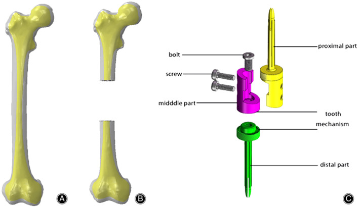
Establishment of the digital model. (A) The femoral model is established. The gray is the cortical bone and the yellow is the cancellous bone. (B) 8 cm segment is resected in the middle of the femoral shaft. (C) The diaphyseal prosthesis with tooth mechanism consists of one proximal part, one distal part, one middle part, one bolt, and two screws. The tooth mechanism was made up of the distal edge of the middle part and the proximal edge of the distal part.
Design of Diaphyseal Prosthesis Model
The diaphyseal prosthesis models with/without tooth mechanism were designed in SolidWorks 2016. The prosthesis with tooth mechanism consisted of a proximal part, a distal part, and a middle connection part, and the prosthesis without tooth mechanism consisted of a proximal part and a distal part. The proximal part and the distal part of the two prostheses each had a fixation stem, and the sizes of the stems were based on the diameter of the medullary cavity of the femoral shaft. The tooth mechanism was made up of the distal edge of the middle part and the proximal edge of the distal part, and rotation can be freely adjusted according to limb alignment. The middle part and the distal part were connected with the sleeve structure and fixed by a bolt. The proximal part and middle connection parts were connected with a lap joint and fixed by two screws (Fig. 1C).
Establishment of Finite Element Analysis (FEA) Model
The prosthesis models with/without tooth mechanism and the femur model after osteotomy were imported into the FEA software Abaqus 2016 (Dassault Systèmes, France). Based on our previous research14, they were assigned, assembled, and meshed in Abaqus 2016 (Fig. 2A,B). The material characteristics and element types of the FEA models in our research were shown in Table 1.The 3D FEA models with 10‐node quadratic tetrahedron elements (C3D10) were used to model the femur and the prosthesis, and 20‐node quadratic hexahedron elements (C3D20) were used to model the screw and the bolt. An average element size of 1.4 mm was used for the prosthesis, while the femur, the screw and the bolt element sizes were 1.3, 1.2, and 1.2 mm respectively. The details of the FEA model mesh are shown in Fig. 2C, D. The total elements of the prosthesis model with tooth mechanism are 987,082 (femur model 714,290 and prosthesis model 272,792, respectively) and the total elements of the other model are 992,511 (femur model 714,290 and prosthesis model 278,221, respectively).
Figure 2.
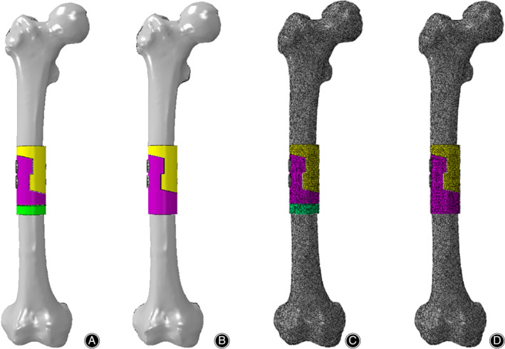
Establishment of the FEA models. (A, B) The FEA models of the reconstruction of a femoral shaft defect using a diaphyseal prosthesis with/without tooth mechanism. (C, D) Meshing of the FEA models.
Table 1.
Material characteristics and element types used in the FEA model
| Young's Modulus | Poisson's ratio | Type | Element | |
|---|---|---|---|---|
| Femoral cortex | 18.6 | 0.3 | C3D10 | 714290 |
| Distal femur | 18.6 | 0.3 | C3D10 | 368056 |
| Proximal femur | 18.6 | 0.3 | C3D10 | 346234 |
| Prosthesis with tooth mechanism | 110 | 0.33 | C3D10 | 272792 |
| Distal part | 110 | 0.33 | C3D10 | 107813 |
| Middle part | 110 | 0.33 | C3D10 | 51811 |
| Proximal part | 110 | 0.33 | C3D10 | 108612 |
| Screw | 110 | 0.33 | C3D20 | 2400 |
| Bolt | 110 | 0.33 | C3D20 | 2156 |
| Prosthesis without tooth mechanism | 110 | 0.33 | C3D10 | 278221 |
| Distal part | 110 | 0.33 | C3D10 | 167209 |
| Proximal part | 110 | 0.33 | C3D10 | 108612 |
| Screw | 110 | 0.33 | C3D20 | 2400 |
In order to reduce the calculation time, the FEA model was simplified to direct contact between the prosthetic stem and intramedullary walls of the femur, and the cancellous bone was neglected due to its little effect. The main purpose of this study is to test the properties of the prosthesis, and the femur is only used as a load carrier and transmitter. Therefore, the femur in the model is assumed to be homogeneous, continuous, isotropic, and linear elastic. The implants are assumed to be made of commercially pure titanium, so it also can be regarded as a homogeneous, isotropic, and linear elastic material, and its deformation is small. The material properties of the bone and prosthesis in FEA were based on previous studies15, 16.
Interaction, Constraint, and Load
The mechanical contacts between the prosthesis and femoral osteotomy surface, and between parts of the prosthesis, were defined via a standard contact between the matching surfaces in both contact bodies. They were considered as a finite sliding case with friction, and the Coulomb friction model was used. The coefficients of friction used were μ = 0.1 for the contact between the prostheses and μ = 0.3 for the contact between the prostheses and the osteotomy surfaces17. The contacts between the prosthetic stems and intramedullary walls of the femur, and between the screws/bolt and the prostheses, were referred to as “tie” cases. In the study, we simulate three biomechanical tests (the compression test, the torsion test, and the 3P‐bending test) under broken load to assess the biomechanical strength of the two prostheses. In the compression test, the FEA model was analyzed with the boundary condition of zero at the distal end of the femur and a loading of 3000 N down load (about 4.5 times the patient's body weight) along the femoral force line on the top of the proximal femur (Fig. 3A). In the torsion test, the model was analyzed with the boundary condition of zero at the distal end of the femur and a loading of 30 Nm internal torque along the femoral force line on the top of the proximal femur (Fig. 3B). In the three‐point bending (3P‐bending) test, the model was analyzed with the boundary condition of zero at both ends of the femur and a loading of 3000 N lateral load vertical to the femoral force line on the medial area of the whole FEA model (Fig. 3C).
Figure 3.
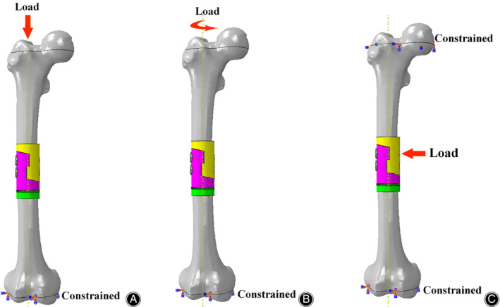
Boundary conditions and load applied to the femoral FEA model. (A) Compression test. (B) Torsion test. (C) 3P‐bending test.
Mechanical Test
Our previous research showed that the FEA model of prostheses without tooth mechanism was capable of precisely predicting its biomechanical properties14. So, in this research, we used the same method to apply the pressure and torque to the femur–prosthesis with tooth mechanism using the MTS mechanical testing machine (MTS Bionix, China). Five cycles of 0–500 N load in compression tests and five cycles of 0–5 Nm internal torque in torsion tests were applied, respectively. When each cycle of loading was finished, the specimen was examined for implant loosening and the presence of cracks. The displacement under 500 N pressure and torsion angles under 5 Nm torque were recorded and the averages of the data were computed.
Main Outcome Measure
The stress distribution can visually observe the stress concentration and highlight the dangerous areas of the bone‐prosthesis constructs, which are distinguished by color, from blue to red, indicating a gradual increase in stress. Red indicates the maximum stress, which means that the part is likely to fail. In contrast, blue indicates the minimum stress, which means the part is unlikely to fail.
The von Mises stress (equivalent stress) is the main outcome measure in the study. It is usually used to evaluate fatigue and failure of materials. When the von Mises stress (the equivalent stress) reaches a fixed value, the material will yield.
Results
FEA Validation
The specimen was loaded five times within their linear elastic region in compression tests and in torsion tests. There were no prosthesis or cadaveric femur failures. No prosthesis or screw loosening was detected after each loading. To simulate the mechanical test as far as possible, the same boundary condition was set up for FEA (Fig. 4). Displacements under 500 N load and angles under 5 Nm torque in mechanical tests and FEA, as well as their differences, were shown in Table 2. The differences in compression tests and torsion tests were 4.88% and 8.29% respectively, so we concluded that the FEA model of prostheses with tooth mechanism could also precisely predict its biomechanical properties.
Figure 4.
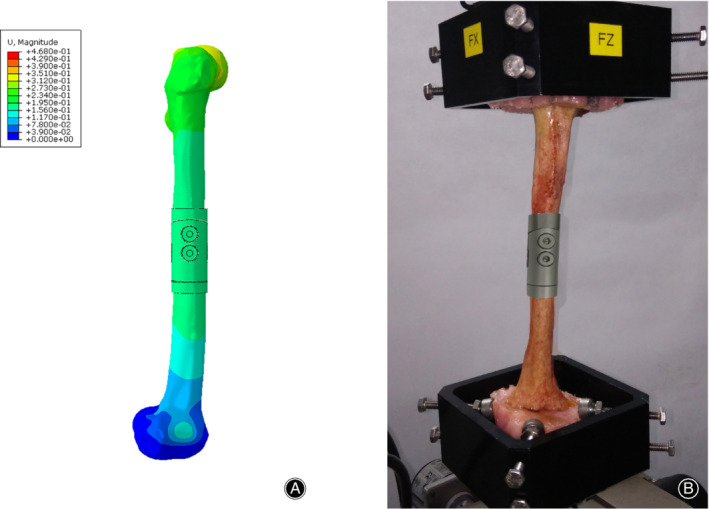
FEA validation. To simulate the mechanical test as far as possible, the same boundary condition was set up for FEA. (A) Mechanical test. (B) FEA.
Table 2.
Differences of displacement (mm) under 500 N load and torsion angle (°) under 5 Nm torque between mechanical testing and FEA
| Mechanical testing | FEA | Difference (%) | |
|---|---|---|---|
| Displacement | 0.492 ± 0.052 | 0.468 | 4.88% |
| Angle | 2.368 ± 0.710 | 2.582 | 8.29% |
Stress Distribution of FEA Under Broken Load
The stress distributions of bone‐prosthesis constructs were presented with different colors according to the magnitude of stress in the compression, torsion, and 3P‐bending tests (Figs 5, 6, 7). Similar stress distributions of the two models were observed in each test. In the compression test, the stress was concentrated on both ends of the femur and the stress of the prostheses was much smaller. In the torsion and 3P‐bending tests, the stress was primarily concentrated in the middle of the protheses and the stress of the femur was much smaller.
Figure 5.
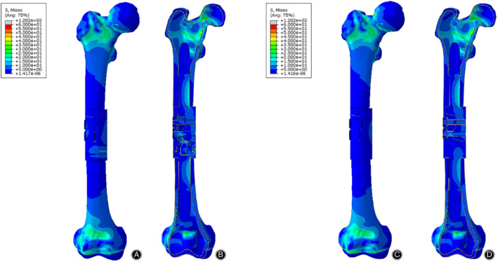
The Von Mises stress distribution of bone‐prosthesis constructs in the compression test. The stress was concentrated on both ends of the femur. (A) Front view of bone‐prosthesis constructs with tooth mechanism. (B) Section view of bone‐prosthesis constructs with tooth mechanism. (C) Front view of bone‐prosthesis constructs without tooth mechanism. (D) Section view of bone‐prosthesis constructs without tooth mechanism.
Figure 6.
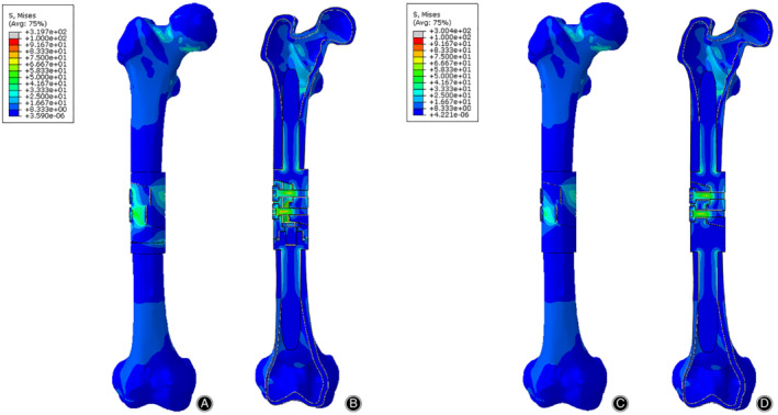
The Von Mises stress distribution of bone‐prosthesis constructs in the torsion test. The stress was concentrated in the middle of the prosthesis. (A) Front view of bone‐prosthesis constructs with tooth mechanism. (B) Section view of bone‐prosthesis constructs with tooth mechanism. (C) Front view of bone‐prosthesis constructs without tooth mechanism. (D) Section view of bone‐prosthesis constructs without tooth mechanism.
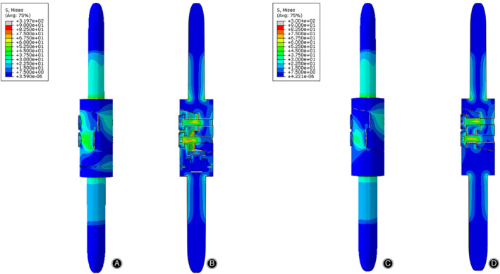
Figure 7.
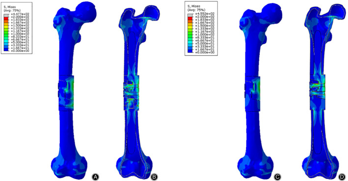
The Von Mises stress distribution of bone‐prosthesis constructs in the 3P‐bending test. The stress was concentrated in the middle of the prosthesis. (A) Front view of bone‐prosthesis constructs with tooth mechanism. (B) Section view of bone‐prosthesis constructs with tooth mechanism. (C) Front view of bone‐prosthesis constructs without tooth mechanism. (D) Section view of bone‐prosthesis constructs without tooth mechanism.
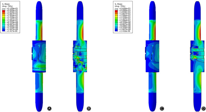
The stress distributions of the prostheses with/without tooth mechanism were presented with different colors according to the magnitude of stress in three tests (Figs 8, 9, 10). The stress distributions of the two prostheses were also similar in three tests. In the compression test, the stress was concentrated in the medial and posterior side of the prostheses, especially in both stems of the prostheses. In the torsion test, the stress was primarily concentrated in the middle of the protheses, especially in the screws and the posterior side of the lap joint of the prosthesis. In the 3P‐bending test, the stress was primarily concentrated in the screws and the medial side of the prostheses, especially in the screws.
Figure 8.
The Von Mises stress distribution of the prostheses in the compression test. The stress was mainly concentrated on the medial and posterior side of the prosthesis. (A) Front view of the prosthesis with tooth mechanism. (B) Section view of the prosthesis with tooth mechanism. (C) Front view of the prosthesis without tooth mechanism. (D) Section view of the prosthesis without tooth mechanism.
Figure 9.
The von Mises stress distribution of the prostheses in the torsion test. The stress was mainly concentrated on the anterior side of the lap joint of the prostheses. (A) Front view of the prosthesis with tooth mechanism. (B) Section view of the prosthesis with tooth mechanism. (C) Front view of the prosthesis without tooth mechanism. (D) Section view of the prosthesis without tooth mechanism.
Figure 10.
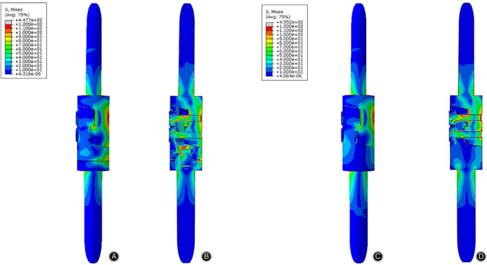
The von Mises stress distribution of the prosthesis in the 3P‐bending test. The stress was mainly concentrated on the medial side of the prosthesis. (A) Front view of the prosthesis with tooth mechanism. (B) Section view of the prosthesis with tooth mechanism. (C) Front view of the prosthesis without tooth mechanism. (D) Section view of the prosthesis without tooth mechanism.
Maximum Von Mises Stress of Finite Element Analysis (FEA) Under Broken Load
The results of the maximum von Mises stress in three tests were shown in Table 3. Because the stresses of the bone‐prosthesis constructs were concentrated in both ends of the femur in the compression test, the maximum von Mises stresses on the femurs (120.2 and 120.2 MPa, respectively) were much larger (about 3.81 and 4.58 times) than that on the prostheses (31.55 and 26.26 MPa, respectively). The maximum von Mises stress on the prosthesis with tooth mechanism was registered in the posterior side of tooth mechanism, and the maximum von Mises stress on the prosthesis without tooth mechanism was registered in the proximal screw hole of the proximal part. In the torsion and 3P‐bending tests, the stresses of the bone‐prosthesis constructs were concentrated in the prostheses. The maximum von Mises stresses on the two prostheses were both registered in the proximal screw hole of the proximal part.
Table 3.
Maximum Von Mises stress on the FEA model
| S Mises (MPa)* | Compression test | Torsion test | 3P‐bending test |
|---|---|---|---|
| Bone‐prosthesis with tooth mechanism | 1.202e+02 | 3.197E+02 | 4.477E+02 |
| Bone‐prosthesis without tooth mechanism | 1.202e+02 | 3.004E+02 | 4.552E+02 |
| Prosthesis with tooth mechanism | 3.155E+01 | 3.197E+02 | 4.477E+02 |
| Prosthesis without tooth mechanism | 2.626E+01 | 3.004E+02 | 4.552E+02 |
Maximum Von Mises stress.
In terms of the prosthesis with/without tooth mechanism, we could easily observe that their maximum von Mises stresses were both very close in each test (Fig. 11). In the compression and torsion test, the maximum von Mises stresses on the prosthesis with tooth mechanism (31.55 and 319.7 MPa, respectively) were slightly larger (about 1.20 and 1.06 times) than those on the prosthesis without tooth mechanism (26.26 and 300.4 MPa, respectively). In the 3P‐bending test, the maximum von Mises stresses on the prosthesis with tooth mechanism (447.7 MPa) was slightly smaller (about 0.98 times) than that on the prosthesis without tooth mechanism (455.2 MPa).
Figure 11.
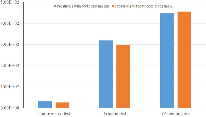
The maximum Von Mises stress (MPa) of the prosthesis with/without tooth mechanism in the three tests. The maximum Von Mises stresses of the two prostheses were very close.
Discussion
In our study, we designed a diaphyseal prosthesis with tooth mechanism to adjust the rotation of the long bone during the reconstructive operation of the long bone defect. Using the diaphyseal prosthesis can minimize the risk of long bone rotation deformity as much as possible. The assembly method of the prosthesis is as follows. First, the distal part and the proximal part are implanted in the medullary cavities with cement. Second, the middle part is assembled with the proximal part without screws, and then the middle part and the distal part of the prosthesis are reduced according to the lower limb force line. Third, when the lower limb force line becomes normal, separate the middle part from the proximal part, and fix the middle part and the distal part with a bolt. Finally, the middle part and the proximal part are reduced and fixed by two screws. After the above steps, we can freely adjust the rotation of the reconstructed long bone even if the cement hardens.
FEA is used for biomechanical research due to its special advantage of high‐accuracy simulation of complex shapes and material properties18, 19. In order to test the diaphyseal prosthesis, we established a femoral model and two diaphyseal prosthesis models; one with tooth mechanism and the other without tooth mechanism. We simulated the broken load conditions using the FEA method to assess the biomechanical strength of the prosthesis. Our results showed that the stress distributions for the two prostheses with/without tooth mechanism were similar, and the maximum von Mises stress on the prostheses with/without tooth mechanism were very close.
The prosthesis may be at risk of failure based on how close its stress was to the material's ultimate tensile strength (UTS) or ultimate compressive strength (UCS)20. In our study, the maximum von Mises stresses of the prostheses with/without tooth mechanism were far below the UTS (976.0 MPa) of the titanium alloy21, 22. So, we believe that the diaphyseal prosthesis with/without tooth mechanism will not break or fail whether in the compression, torsion, or bending situation.
Furthermore, in the compression and torsion test, the maximum von Mises stresses on the prosthesis with tooth mechanism was larger than those on the prosthesis without tooth mechanism. This meant that the prosthesis with tooth mechanism has weaker anti‐compression and anti‐torsion ability than the prosthesis without tooth mechanism under compression and torsion situations. In the 3P‐bending test, the maximum von Mises stresses on the prosthesis with tooth mechanism were smaller than those on the prosthesis without tooth mechanism. It indicated that the prosthesis with tooth mechanism has stronger anti‐bending ability than the prosthesis without tooth mechanism in bending situations.
There are some limitations to our study and some further research is needed. Because the main purpose of this study was to verify the properties of the prosthesis, some conditions were simplified. For example, the effect of soft tissue, such as the muscle and ligaments, is not considered in the study. The loading force is idealized and directly loaded on the femur along the femoral force line. Considering the cancellous bone has little effect on the properties of prosthesis, the cancellous bone is neglected. Consequently, the results cannot truly reflect the complexity of the stress distribution in the actual movement. To simplify calculations and save the calculation time, all materials involved in the study are assumed to be homogeneous, continuous, and isotropic and with linear elastic behavior, which does not conform to the actual characteristics of the real materials. In fact, the real materials are non‐homogeneous, discontinuous, and heterosexual. Moreover, the fatigue test should be performed to evaluate the fatigue damage performance of the diaphyseal prosthesis with tooth mechanism, and the prosthesis should aslo be verified by clinical research in the future.
Conclusion
To adjust the rotation of the long bone during the operation, we designed a diaphyseal prosthesis with tooth mechanism, and then used the 3D FEA method to simulate the stress of the bone‐prosthesis constructs under violence conditions and evaluate the diaphyseal prosthesis from a biomechanical point of view. We conclude that the diaphyseal prosthesis with tooth mechanism has a good biomechanical performance and does not increase the risk of failure or breakage of the prosthesis.
Disclosure: The authors have declared no conflict of interest.
References
- 1. Boyle M, Tebbi CK, Mindell ER, Mettlin CJ. Adolescent adjustment to amputation. Med Pediatr Oncol, 1982, 10: 301–312. [DOI] [PubMed] [Google Scholar]
- 2. Simon MA, Aschliman MA, Thomas N, Mankin HJ. Limb‐salvage treatment versus amputation for osteosarcoma of the distal end of the femur. J Bone Joint Surg Am, 1986, 68: 1331–1337. [PubMed] [Google Scholar]
- 3. Lempberg R, Ahlgren O. Prosthetic replacement of tumour‐destroyed diaphyseal bone in the lower extremity. Acta Orthop Scand, 1982, 53: 541–545. [DOI] [PubMed] [Google Scholar]
- 4. Chin HC, Frassica FJ, Hein TJ, et al Metastatic diaphyseal fractures of the shaft of the humerus. The structural strength evaluation of a new method of treatment with a segmental defect prosthesis. Clin Orthop Relat Res, 1989, 248: 231–239. [PubMed] [Google Scholar]
- 5. Abudu A, Carter SR, Grimer RJ. The outcome and functional results of diaphysealendoprostheses after tumour excision. J Bone Joint Surg Br, 1996, 78: 652–657. [PubMed] [Google Scholar]
- 6. Damron TA, Sim FH, Shives TC, An KN, Rock MG, Pritchard DJ. Intercalary spacers in the treatment of segmentally destructive diaphyseal humeral lesions in disseminated malignancies. Clin Orthop Relat Res, 1996, 324: 233–243. [DOI] [PubMed] [Google Scholar]
- 7. Sewell MD, Hanna SA, McGrath A, et al Intercalary diaphyseal endoprosthetic reconstruction for malignant tibial bone tumours. J Bone Joint Surg Br, 2011, 93: 1111–1117. [DOI] [PubMed] [Google Scholar]
- 8. Lun D, Hu Y, Yang X, Wang F, Xu ZW. Short‐term outcomes of reconstruction subsequent to intercalary resection of femoral diaphyseal metastatic tumor with pathological fracture: comparison between segmental allograft and intercalary prosthesis. Oncol Lett, 2018, 15: 3508–3517. [DOI] [PMC free article] [PubMed] [Google Scholar]
- 9. Hanna SA, Sewell MD, Aston WJ, et al Femoral diaphyseal endoprosthetic reconstruction after segmental resection of primary bone tumours. J Bone Joint Surg Br, 2010, 92: 867–874. [DOI] [PubMed] [Google Scholar]
- 10. Ahlmann ER, Menendez LR. Intercalary endoprosthetic reconstruction for diaphyseal bone tumours. J Bone Joint Surg Br, 2006, 88: 1487–1491. [DOI] [PubMed] [Google Scholar]
- 11. Aldlyami E, Abudu A, Grimer RJ, Carter SR, Tillman RM. Endoprosthetic replacement of diaphyseal bone defects. Long‐term results. IntOrthop, 2005, 29: 25–29. [DOI] [PMC free article] [PubMed] [Google Scholar]
- 12. Damron TA, Leerapun T, Hugate RR, Shives TC, Sim FH. Does the second‐generation intercalary humeral spacer improve on the first?. Clin Orthop Relat Res, 2008, 466: 1309–1317. [DOI] [PMC free article] [PubMed] [Google Scholar]
- 13. Zhang JF, Wang F, Hu YC. Reconstruction of humeral shaft defect with an intercalary endoprosthesis following resection of tumor. Orthop Surg, 2018, 10: 281–284. [DOI] [PMC free article] [PubMed] [Google Scholar]
- 14. Zhao LM, Tian DM, Wei Y, et al Biomechanical analysis of a novel intercalary prosthesis for humeral diaphyseal segmental defect reconstruction. Orthop Surg, 2018, 10: 23–31. [DOI] [PMC free article] [PubMed] [Google Scholar]
- 15. Mitsuo N. Recent research and development in titanium alloys for biomedical applications and healthcare goods. Sci Technol Adv Mater, 2003, 4: 445–454. [Google Scholar]
- 16. Cristofolini L, Viceconti M. Mechanical validation of whole bone composite tibia models. J Biomech, 2000, 33: 279–288. [DOI] [PubMed] [Google Scholar]
- 17. Viceconti M, Muccini R, Bernakiewicz M, Baleani M, Cristofolini L. Large Sliding contact elements accuratelty predict levels of bone‐implant micromotion relevant to osseointegration. J Biomech, 2000, 33: 1611–1618. [DOI] [PubMed] [Google Scholar]
- 18. Huiskes R, Chao EYS. A survey of finite element analysis in orthopedic biomechanics: the first decade. J Biomech, 1983, 16: 385–409. [DOI] [PubMed] [Google Scholar]
- 19. Hannah I, Harland A, Price D, Schlarb H, Lucas T. Evaluation of a kinematically‐driven finite element footstrike model. J Appl Biomech, 2016, 32: 301–305. [DOI] [PubMed] [Google Scholar]
- 20. Coquim J, Clemenzi J, Salahi M, et al Biomechanical analysis using FEA and experiments of metal plate and bone strut repair of a femur midshaft segmental defect. Biomed Res Int, 2018, 2018: 4650308. [DOI] [PMC free article] [PubMed] [Google Scholar]
- 21. Wang K. The use of titanium for medical applications in the USA. Mater Sci Eng A, 1996, 213: 134–137. [Google Scholar]
- 22. Niinomi M. Mechanical properties of biomedical titanium alloys. Mater Sci Eng A, 1998, 243: 231–236. [Google Scholar]