Abstract
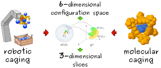
We define a molecular caging complex as a pair of molecules in which one molecule (the “host” or “cage”) possesses a cavity that can encapsulate the other molecule (the “guest”) and prevent it from escaping. Molecular caging complexes can be useful in applications such as molecular shape sorting, drug delivery, and molecular immobilization in materials science, to name just a few. However, the design and computational discovery of new caging complexes is a challenging task, as it is hard to predict whether one molecule can encapsulate another because their shapes can be quite complex. In this paper, we propose a computational screening method that predicts whether a given pair of molecules form a caging complex. Our method is based on a caging verification algorithm that was designed by our group for applications in robotic manipulation. We tested our algorithm on three pairs of molecules that were previously described in a pioneering work on molecular caging complexes and found that our results are fully consistent with the previously reported ones. Furthermore, we performed a screening experiment on a data set consisting of 46 hosts and four guests and used our algorithm to predict which pairs are likely to form caging complexes. Our method is computationally efficient and can be integrated into a screening pipeline to complement experimental techniques.
1. Introduction
Recent advances in synthetic chemistry have led to the discovery of many classes of chemical compounds possessing interesting geometric and topological features: linking (catenanes, molecular Borromean rings),1 caging (molecular cages),2 cavities (cavitands),3 etc. From both chemical and topological perspectives, molecular cages have an important feature—an internal cavity. Like other types of molecules possessing cavities, such as certain enzymes or cavitands, molecular cages can be involved in supramolecular interactions, in particular of the host–guest type. In this case, a hollow space inside the host can serve both as a binding site for the guest and as a nanoreactor environment.4
A host (or cage) is a molecule or a macromolecular complex that possesses an internal cavity. A guest is a small molecule that can potentially fit within the cavity of the host. Here we define a caging complex as a host–guest pair in which the mobility of the guest is restricted and the guest cannot escape arbitrarily far. Given that caging is a property describing a pair of molecules, we say that the host cages the guest and that the guest is caged by the host (see Figure 1).
Figure 1.

Depending on the relative sizes and shapes of a guest (red) and a host (blue), the guest mobility can be constrained. If the guest both can be placed inside the host cavity and cannot escape, it is caged (b); otherwise it is not caged (a, c). More precisely, (a) the guest might be too small and enter/exit the cavity through the host windows; (b) the guest might match the size/shape of the host cavity and be “caged”; or (c) the guest might be too big to fit within the cavity. In this example, we do not discuss how these pairs are formed.
Hosts are typically constructed with dynamic covalent bonds, meaning that their formation and decomposition are achieved through simple chemical reactions that proceed with high efficiency.5 This feature offers the possibility to assemble a host around a guest molecule and disassemble it under some external stimulus (light, temperature, chemical stimulus, pH, etc.).6−8 A caging complex therefore represents a nanoscale carrier–cargo pair that can be securely stored and transported without any leakage of cargo and discharged when needed. These properties meet the demands of many fields of life science: drug delivery, medical imaging, sensing, etc.9,10 Therefore, the discovery of new caging complexes along with modern methods of controlled cage self-assembly constitutes a powerful tool for biomedical applications.11
Depending on the area of application, the development of new caging complexes can employ different strategies. For example, if a newly developed host is considered as a potential selective gas filter, the screening of various gaseous guests is required to understand which molecules can pass the filter and which cannot penetrate the host shell. In contrast, if a real technological problem relates to the separation of two particular compounds, the screening of various hosts is necessary to find a host that possesses different permeation behaviors for two guests.12,13 In drug delivery, a similar screening of hosts would be necessary if a particular drug molecule needs to be caged and subsequently carried by a host.
After more than 30 years since the first high-yielding synthesis of a host molecule with a well-defined structure, the targeted synthesis of shape-persistent cages with big cavities remains a challenge.14 Since the formation of a caging complex includes preparing a host, the experimental discovery of new complexes is hampered by the time-consuming15 or expensive16 procedures of host synthesis. Therefore, most caging complexes discovered to date simply represent crystals of shape-persistent cages with solvent molecules entrapped inside the cavity.12
Significant experimental challenges make a high-throughput synthetic approach to a caging complex discovery very resource-demanding, thus highlighting the need for theoretical approaches. Being able to predict caging complexes theoretically, one would narrow the scope of host and guest candidates subjected to experimental screening. Then the process of discovery of new caging complexes would reduce to the following: (i) select caging complex candidates (host–guest pairs); (ii) represent hosts and guests in a form suitable for in silico analysis; and (iii) for each pair, determine whether it is likely to form a caging complex. Recent progress in the computational prediction of host structure allows the efficient generation of molecular geometries of shape-persistent cages without synthesizing them.16,17 With molecular structures in hand, the only missing component of the theoretical caging prediction is an algorithm that takes two geometries as input and evaluates whether two molecules form a caging complex.
The goal of the present work is to develop a computational method to identify pairs of molecules that are likely to form a caging complex. Our approach is based on our previous work,18,19 where we presented an algorithm that determines whether a three-dimensional geometric body can cage another one. In the general case, both geometric bodies can have arbitrary shapes and are represented as unions of balls of arbitrary radii. This algorithm was originally designed for applications in robotic manipulation and path planning, where the notion of caging has been independently studied for several decades.20
In this paper, we propose a computational screening method that predicts whether a pair of molecules form a caging complex. Given two fixed conformations of a host and a guest, we evaluate whether they form a caging complex, and if they do, how robust the obtained cage is with regard to fluctuations in the input geometries. As the potential application of this framework lies in the field of drug development and screening, we wish to remain on the side of caution. In other words, if the algorithm cannot provide theoretical guarantees of the existence of a caging complex, we do not consider a given host–guest pair to be a caging complex. When our algorithm reports that a pair of molecules do form a caging complex, this can be proven mathematically.
It should be noted that our method involves the use of static molecular geometries, i.e., the so-called “solid sphere model”. More precisely, each molecule is represented by a union of balls with fixed radii. To enhance this representation and assess the robustness of the results produced by our method, we consider uncertainties in the definition of these molecular geometries. We also show how molecular flexibility can be taken into account implicitly by considering several conformations of a given host. However, a full treatment of molecular flexibility goes beyond the scope of this article and is only discussed as future work.
The rest of the paper is organized as follows: in section 2, we discuss existing approaches to the computational prediction of caging complexes. In section 3, we discuss the notion of caging in robotics. In section 4, we present a theoretical formulation of the problem. Later, in section 5, we describe our caging prediction algorithm. Section 6 reports our experimental results. Section 7 provides a discussion of our work, and section 8 concludes the paper.
2. Computational Prediction of Caging Complexes
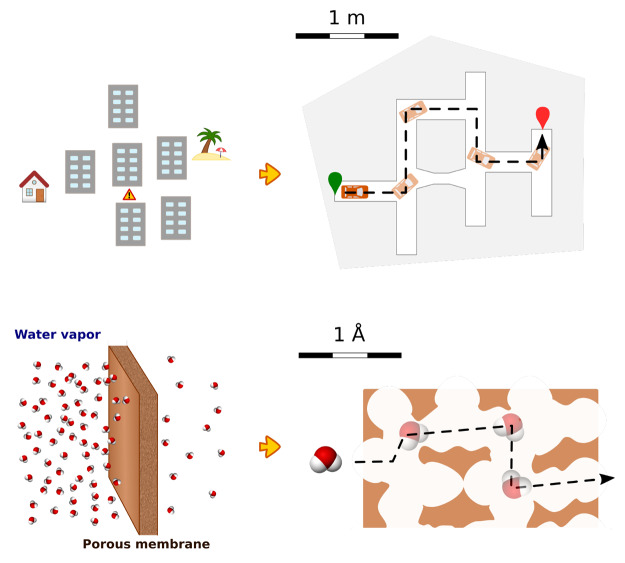
While the motion of particles in fluids generally has a random nature, many chemical and biological processes rely on specific movements of molecules such as migration of a molecule from one environment to another, avoiding some obstacles. These include but are not limited to diffusion through a cell wall, approaching and binding an enzyme active site, and permeation through a solid membrane. The latter process is related to a common task existing in the macroscopic world: finding a path between two points in space (see Figure 2). In other words, given the starting and final positions of an object, one needs to find a continuous set of positions of the moving object avoiding collisions with the environment. Unlike macroscopic objects, individual molecules are not easy to manipulate. Instead, the statistical nature of their motion allows them to find such paths without direct manipulation.
Figure 2.
Movement of an object in an urban environment (top) can be formulated in the same geometric terms as the movement of a molecule in a nanoscale environment (bottom).
A dual problem to path finding—proving path nonexistence—naturally occurs in the case of porous solids in gas separation processes.21 In general, analyzing the shapes of gas molecules and material pores allows the prediction of how fast the molecule will permeate through the material. However, the porous structure of most solids, including crystals, is not entirely determined by their molecular structure and can depend on experimental conditions, thus rendering its computational prediction very challenging.22
Path-finding problems can be tackled using classical motion planning techniques. Sampling-based path-planning algorithms, originally designed for robotics applications, have gained a lot of attention in the context of modeling molecular motion (see a recent survey23 for an overview of the state of the art). Robotics-inspired methods that were developed to determine ligand unbinding pathways, such as MoMa LigPath, can also be used for the caging prediction.24 Indeed, if an unbinding pathway is found, one can conclude that the ligand cannot be caged by the tested host. Unfortunately, no conclusion can be reached if no unbinding pathway is found because such methods cannot prove path nonexistence. Another drawback of these methods is that they are not computationally efficient. On the other hand, an advantage of these methods is their ability to explicitly consider molecular flexibility.
While the modeling of molecular motions as paths in the molecule’s configuration space is not novel per se, in this paper, we address a problem that is dual to that of path planning: we want to identify situations where there is no path. The key difference between sampling-based path-planning algorithms and our approach is that the former are not able to identify situations where there is no path and are only “probabilistically complete”: they are guaranteed to find a valid path, if one exists, as the number of samples goes to infinity. In situations where there is no path, they need to rely on heuristics to stop the search and thus are not able to provide any guarantee that one molecule restricts the mobility of the other. In this paper, we establish a connection between another problem from the field of robotics and molecular applications: the caging problem.
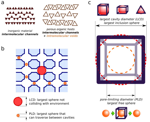
Unlike intermolecular channels in inorganic porous materials that result from the complex interaction of dozens of molecules, the so-called permanent porosity in organic cages is determined and maintained by a single molecule possessing an internal cavity25 (see Figure 3a). This unique property of organic cages allows for the targeted development of materials and molecules containing well-defined pores, in particular those that can cage other molecules. Such development can be realized via the computational prediction of both the host structure and its properties, such as the ability to cage certain guest molecules.
Figure 3.
(a) Schematic representation of solids containing molecules without and with internal cavities. (b, c) Illustrations of the largest cavity diameter (LCD) and pore-limiting diameter (PLD) applied to (b) porous materials and (c) molecular cages.
2.1. Overview of Existing Approaches
Many hosts with cavities are constructed of wire-shaped building blocks and have large windows connecting the internal cavity with the environment.16,26,27 On the one hand, these features allow for a straightforward synthesis via the self-assembly of simple starting materials; on the other hand, they lead to the formation of a large void space inside the molecule along with big openings in the “shell” surrounding the cavity. Thus, the problem of rational design of a caging complex (finding a guest that is caged by a given host, or finding a host that cages a given guest) usually includes addressing two main questions:
Can the guest fit the inner cavity of the host?
Can the guest escape through the openings (windows) in the host shell?
Several methods based on a computational geometry framework and targeting various modifications of this problem have been developed in recent years. Most of them were designed for the analysis of porous materials and their adsorption of simple guests: monatomic or diatomic gases (or, less often, organic vapors). Since these molecules can be represented geometrically as one or two balls, respectively, the following two geometric parameters, which are the most widely used, evolved: (1) the largest inclusion sphere (or largest cavity diameter, LCD), and (2) the largest free sphere (or pore-limiting diameter, PLD)28,29 (see Figure 3b). Intuitively, the LCD is mostly related to the aforementioned problem of fitting the guest into the cavity and the PLD to the problem of guest escape from the cavity.
In general, these two parameters are sufficient to estimate adsorption selectivities among several gases. For example, Sikora et al.30 performed an extensive computational screening of 137 000 theoretical metal–organic frameworks to test the selectivity of Xe/Kr adsorption. The analysis of screening results revealed that materials with pores that can tightly fit a single Xe atom (LCD ≈ Xe atom diameter > Kr atom diameter) and have PLDs small enough to hamper Xe diffusion but big enough to allow for fast Kr penetration are capable of efficient separation of Xe and Kr.
The majority of computational methods used for such analysis involve Voronoi decomposition or Delaunay tesselation of the void space.21,31 Both techniques allow the determination of the LCD and PLD within a reasonable computation time.30,32 However, these methods approximate the shape of the guest as a single sphere, which limits their application to rarely used monatomic gases.
Unlike porous materials, molecular hosts contain cavities (or pores) inside a single molecule. Nevertheless, the LCD and PLD can still be defined for them (see Figure 3c), and the same computational methods can be applied. The recently developed pyWINDOW package addresses the problem of determining the host cavity size (LCD) and host windows diameters (PLD) by using a sampling-based algorithm.33 This approach benefits from the well-defined structure of hosts but is still limited to monatomic guests.
Apart from the aforementioned geometric methods, there exist many simulation methods that can be used to study molecular transport in material cavities.34 Molecular dynamics (MD) remains the ultimate method that allows one to both include chemical interactions and adjust environment parameters. However, MD methods are time-consuming and hence not applicable to screening tasks. They also require the setup of a starting configuration for the host and guest. If the host cavity is tight, finding a noncolliding initial configuration of the guest inside the cavity is not trivial and is related to the problem of fitting the guest molecule inside the host cavity. Therefore, many studies separate dynamic simulations from geometric analysis of static structures.27,33,35
2.2. Open Problems
The definitions of the LCD and PLD (including their analogues in molecular cages) are rather intuitive and are thus commonly used to define the adsorption selectivity of porous materials.29,31,36 From a geometric point of view, these parameters describe only two spheres and thus provide little knowledge about the internal structure of the cavity. Using balls as probes traversing through the porous material is extremely useful for the description of monatomic gas adsorption, since a single atom possesses spherical symmetry and can be modeled as a rigid ball in simulations. However, this approximation becomes less realistic in predictions of diatomic gas adsorption. Eventually, the more complex the shape of the gas molecule becomes, the more knowledge about cavity shapes is required in order to evaluate the material penetration dynamics or the possibility of escaping the host cavity. Therefore, the methods developed to date are limited to spherical guests and cannot be directly applied to arbitrary guest molecules.
To find caging complexes, we utilize the concept of the configuration space of a molecule (or probe). In the case of a spherical probe, the configuration space has only three degrees of freedom, and its dimensionality is thus 3. This space can be explicitly constructed and analyzed using standard computational geometry methods such as those mentioned above. However, a molecule generally has at least six degrees of freedom: three translational, three rotational, and various internal degrees of freedom. Therefore, its configuration space is at least six-dimensional, which makes its direct reconstruction a computationally infeasible problem.20 It should be noted that it is possible to take a holistic approach toward the analysis of porosity and use latent space embedding techniques in order to classify pore sizes and shapes.37 However, these methods do not consider guest molecules and are therefore less precise than those analyzing the configuration space of molecules explicitly. Although many studies that address the prediction of trapping of molecules inside cavities focus on simple shapes such as mono- or diatomic molecules, the caging of organic molecules, both for separation and drug delivery applications, becomes more attractive as more materials exhibiting selectivity are being developed.12,38 To the best of our knowledge, there is currently no general framework that would allow a chemist to determine whether a guest molecule of arbitrary shape can be caged by a host molecule of arbitrary shape.
3. Caging in Robotics
Our approach to determine whether two given molecules form a caging complex is inspired by the notion of caging from robotic manipulation.39 The problem of caging a rigid object has been studied in robotics for several decades. There the goal is to create algorithms that would enable robots to grasp objects reliably and prevent them from escaping from a robotic manipulator (e.g., by falling on the floor). By definition, an object is caged by a robot if it cannot escape arbitrarily far from its initial position (see Figure 4). This is achieved by restricting the object’s mobility by means of robotic manipulators and external obstacles (e.g., walls, table surfaces, etc.). The problem of verifying whether an object is caged is challenging from the geometric point of view.
Figure 4.
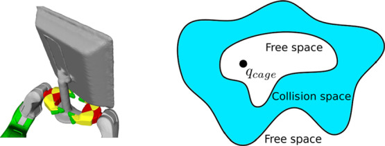
Illustration of the concept of caging in robotics. On the left, an object is caged by two robotic hands: the object is not completely immobilized, but it cannot escape from the manipulator (reprinted with permission from ref (54); copyright 2016 IEEE). On the right, a simplified illustration of its configuration space topology is presented: an object’s configuration is a caging configuration when it is fully surrounded by collision space (in blue). Here, q represents a single configuration of an object.
3.1. Applications of Robotic Caging
In robotics, caging plays an important role in two different applications: robotic grasping and multiagent manipulation. The problem of grasp synthesis consists of finding a grasp configuration that satisfies a set of criteria relevant for the grasping task. The caging problem has been considered either as an alternative or as a preliminary step to forming a grasp.20 For instance, certain tasks, such as carrying objects or opening doors, do not require complete immobilization of an object. Instead, caging can be a more reasonable alternative, as it can be more robust toward uncertainties in an object’s shape and position. Moreover, caging can be used to temporarily restrict the object’s mobility while attempting to grasp it.39
Another important application of caging in robotics lies in the field of multiagent manipulation. Here, a team of mobile robots encloses an object and moves without allowing it to escape at any moment in time.40,41 In this process, the team needs to avoid obstacles, which implies changing the shape of the formation. Caging can be beneficial in this scenario, as it provides theoretical guarantees of object immobilization and does not require explicit force control. In this context, mobile robots are typically represented as points and objects as polygons. Motions are usually performed in a two-dimensional environment.
3.2. Formalization of Robotic Caging
Representing
positions of rigid objects requires specifying all of their degrees
of freedom, both translations and rotations. Modeling begins with
the notion of configuration, that is, a set of independent
parameters that characterize the position of a body in the world.
When the object can freely move in a three-dimensional environment,
its configuration c is described by six independent
parameters specifying its position and orientation in space. The configuration space of a rigid
body is a topological space in
which each point uniquely corresponds to a configuration. A subspace
of the configuration space containing only those configurations of
the object in which it does not collide with obstacles is called the
object’s free space
 . A connected component of the free space is a subspace in which
every pair of points can
be connected by a collision-free path. A connected component is bounded if it has finite size (or, mathematically, if it
is contained in a ball of finite radius) and unbounded otherwise. Exactly one of the components of
  is always
unbounded. Intuitively, it represents
“the outside world”.
This formalism leads to an equivalent definition of caging: an object is caged if it is located in a bounded connected component of its free space. Thus, the question of whether a rigid three-dimensional object can be caged by a set of obstacles of a certain shape (or simply by another object) is equivalent to understanding the topological structure of its free space: if there exists at least one bounded connected component in it, then the object can be caged.
The problem of explicit reconstruction (either exact or approximate) of configuration spaces has been studied for several decades. Reconstruction can be achieved by discretizing the space and representing it as a collection of small geometric primitives, such as rectangles, triangles, or their higher-dimensional analogues. However, the number of geometric primitives grows exponentially with the number of dimensions in the space, resulting in high and practically infeasible memory and time complexity of straightforward reconstruction algorithms. Therefore, configuration space approximation is a challenging problem. In a recent survey on robotic caging,20 Makita and Wan hypothesized that recovering a six-dimensional configuration space is computationally infeasible. Later, we proposed a provably correct algorithm for approximating three- and six-dimensional configuration spaces.18,19 To the best of our knowledge, this is the first algorithm that can solve this problem in real time and has been proven to be mathematically correct. In this work, we apply this algorithm to molecules.
4. Problem Formulation and Modeling
In this section, we formulate the goal of the paper and introduce our modeling approach. Namely, we discuss how we model molecules and their motions in space.
4.1. Problem Statement
In this paper, we address the problem of identifying whether a pair of molecules form a caging complex, which is a key part of the computational discovery of new caging complexes. A proposed workflow of the latter is illustrated in Figure 5, with a particular host–guest pair as an example. Rational design of hosts is usually based on the available building blocks and synthetic methods for their assembly, thus enabling the generation of numerous molecular structures of host candidates16 (Figure 5a). Since the notion of a caging complex is defined geometrically, we consider molecules as geometric objects. Furthermore, in this paper we consider only rigid objects, as deformability is a complex property that is challenging to address. In certain contexts molecules can be treated as rigid bodies. For example, one of the common approaches is to represent a molecule as its most stable conformation16 or a conformational ensemble27 (Figure 5b). Given the fixed atomic positions in each conformation, one can build a space-filling model that can serve as a geometric representation of a molecule42 (Figure 5c). Finally, we apply our algorithm that takes two three-dimensional geometric shapes as input and determines whether they form a caging complex (Figure 5d).
Figure 5.
Geometric
approach for screening of molecular caging complexes:
(a) iterating through a pool of host and guest candidates; (b) selecting
conformations for the analysis; (c) representing conformations as
rigid bodies composed of balls; (d) analyzing the free space of the
guest object. Here, SO(3) is the space of possible
orientations, and  corresponds to different
positions in the
Euclidean space.
4.2. Geometric Representation of Molecules
In reality, molecules are composed of atoms, which can be envisioned as interacting particles with spherical symmetry. Although an atom does not have a particular physical boundary, it is common to define the van der Waals radius (rvdW) of an atom;43 this radius depends on the atom type. In order to model repulsion between molecules, we represent a molecule as a solid body with the shape of the van der Waals surface and an atom as a solid ball with radius rvdW corresponding to the chemical element.43,44 Since rvdW is half of the minimal distance between two noninteracting atoms of the same element, using the van der Waals radius is a natural approach to the space-filling model, which approximates intermolecular interactions as solely geometric intersections. However, in certain cases this model is inaccurate, as it does not take into account non-covalent interactions. Strong specific interactions between the host and the guest might favor certain configurations, so that the guest might not be able to leave the host cavity even without steric restrictions (see section 7).
Typically, one of two sources of molecular structure information is used as a starting point for computations: (molecular or quantum-mechanical) modeling or crystallographic data. In this work, we used crystal structures obtained from the Cambridge Crystallographic Data Centre (CCDC) database. Structures of compounds that cannot be crystallized in conditions suitable for X-ray diffraction (e.g., liquids) were extracted from crystal structures of clathrates (where solvent molecules are entrapped in the crystal). Most of the structures used in this work possess a single stable conformation.
4.3. Configuration Space of a Molecule
Here
we investigate the ability of a molecule to move from one area
of space to another in principle. Therefore, we assume that a molecule
can move arbitrarily in a continuous fashion. In other words, if two
configurations are connected by a continuous curve in  (see section 3.2), we say that there exists a path connecting them, and a molecule can move between these configurations.
It should be noted that we do not consider any force exerted by the
real physical environment, and therefore, we do not make any assumption
about the probability or time of transition between configurations.
Analogously to rigid objects, we can define connected components
of the free space of a molecule. If a pair of molecules is a caging
complex, then  contains at least one bounded
connected
component. Points inside bounded components correspond to configurations
of the guest inside the cavity of the host from which it cannot escape
arbitrarily far. To predict whether two molecules form a caging complex,
we approximate the free space
  of the guest and analyze its connected
components. If there are bounded connected components, then the pair
form a caging complex. It should be noted that computing potential paths of guests is beyond the scope of this paper; instead,
our goal is to analyze the existence of such paths
between different parts of the configuration space.
5. Geometric Algorithm for Molecular Caging Prediction
Since the configuration space of a molecule is six-dimensional with the representation we use, we can apply our geometric algorithm18,19 to approximate the free space of a guest. As a result, we get a list of connected components of the free space of the guest. Let us now briefly summarize the key steps of the configuration space approximation algorithm.
5.1. Slice-Based Representation of the Configuration Space
We represent the configuration space  of a guest
as the Cartesian product
where  and SO(3) are the translational
and rotational components, respectively. Instead of explicitly reconstructing
a six-dimensional configuration space, which is computationally infeasible,
we represent it as a set of “slices”—parts of
the configuration space that correspond to small fixed-orientation
neighborhoods (see Figure 6). More specifically, a slice (Sl) is the
Cartesian product of the translational component
  of the configuration space and a small
neighborhood Ui ⊂ SO(3) of the rotational component:
In this way, we approximate  as the union
of a finite set of slices,
i.e.,
  = ∪iSl(Ui), where the set of all orientation neighborhoods Ui covers the entire rotation
space:
This approach allows us to overcome the main computational challenge, namely, the high dimensionality of the space. Instead of explicitly constructing and storing the entire six-dimensional space, we approximate it as a set of three-dimensional approximations Sla(Ui) of slices Sl(Ui). Each approximation is computed by fixing a particular orientation from Ui.
Figure 6.
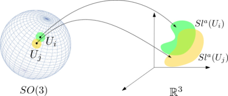
We decompose the configuration space of a rigid body into
a product
of orientational and translational subspaces (SO(3)
and  , respectively). The orientation
space is
subdivided into a finite number of neighborhoods, and each of them
is projected into translational space. The sphere on the left is a
simplified illustration of SO(3); the green and yellow
patches represent overlapping orientation neighborhoods (Ui and Uj). Their respective slice approximations are visualized
on the right (Sla(Ui) and Sla(Uj), in green and yellow, respectively).
Let us now introduce the concept of the ε-core of a guest molecule that makes this possible.
5.2. The “ε-Core” of the Guest and Theoretical Guarantees
In order to compute an approximation
of a slice, we introduce the concept of the ε-core of a guest
molecule. Geometrically, it is contained inside the actual molecular
model. If we take a model of the guest molecule and reduce all of
the ball radii by ε > 0, the resulting smaller model is an
ε-core
of the guest model. If we now slightly change the orientation of the
initial guest model while the ε-core remains fixed, the ε-core
will remain inside the rotated model provided that the change in the
guest’s orientation is small enough and is restricted to a
neighborhood Ui ⊂ SO(3). Since the ε-core is located strictly inside
the rotated guest, whenever the ε-core is in collision with
the host, the rotated guest molecule is also in collision. This means
that the collision space of the slice  can be approximated by computing the collision
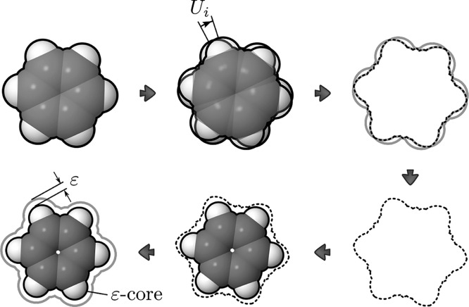
space of the ε-core with a fixed orientation (see Figure 7).
Figure 7.
Illustration of the ε-core principle. First, the intersection I of molecules with all possible orientations within neighborhood Ui is considered (outlined with dashes). Then ε is defined as min Δr for all Δr such that a model with all balls’ radii reduced by Δr is contained strictly inside I.
In our previous work,19 we proved that if the value of ε corresponds to the chosen discretization of the orientation space SO(3), our free-space approximation is conservative, i.e., it is guaranteed to contain the real free space. This guarantee is provided by the notion of the ε-core.
In more detail, let the guest model in some orientation
ϕ
∈ Ui be denoted
by  , and let its geometric
center be the origin.
Consider another orientation θ ∈ Ui and the rotation operator Rϕ→θ(.) that describes the rotation
of
  between the
orientations ϕ and θ.
We assume that the guest is rotated around the origin. Let
  be a point in the guest model in orientation
ϕ and Rϕ→θ(x) its image after application of the rotation operator.
For any pair of orientations ϕ, θ ∈ Ui and any point
  , we define the following
requirement:
| 1 |
where ∥Rϕ→θ(x) – x∥ is the distance between x and Rϕ→θ(x).
Intuitively, for each point x of the guest model  , the distance
between x and its image Rϕ→θ(x) needs to be smaller than ε for all possible
orientation pairs ϕ, θ in Ui (see Figure 7).
Let ρ(ϕ, θ) be the angular
distance between
two elements ϕ and θ in the space of orientations SO(3), defined as45 ρ(ϕ, θ)
= arccos(|⟨ϕ, θ⟩|), where ϕ
and θ are represented as unit quaternions, which are regarded
as vectors in  , and ⟨ϕ, θ⟩
is their inner product. In our previous work,19 we derived the following upper bound for ∥Rϕ→θ(x) – x∥:
where ∥x∥ is the distance between x and the origin.
Now, let Δ(∪iUi) be an upper bound on the distance between any two orientations belonging to the same neighborhood Ui:
To ensure that the requirement given by eq 1 is satisfied, we define the minimal acceptable ε value, denoted by εmin:
| 2 |
In this way, we can guarantee that the ε-core stays inside the rotated guest model provided that ε is greater than or equal to εmin.
The value of Δ(∪iUi) is a parameter of the partitioning of SO(3), ∪iUi (see our previous work19 for more details). Thus, from the chosen partitioning of SO(3), we can find the corresponding value of εmin. As explained in the next section, the values Δ(∪iUi) are computed in advance.
To compute  , we iterate over all atoms and find the
one that is the furthest away from the origin; the sum of this atom’s
radius and the distance from its center to the origin gives us the
distance to the point that is the furthest away from the origin. The
complexity of this procedure is O(n), where n is the number of atoms in
  . In our experiments,
this process takes
less than 1 ms.
5.3. Slice Computation
We choose a discretization of SO(3) and use it as input to our algorithm. In our implementation, we use a grid representation of SO(3) computed with the help of the software provided by Yershova et al.45 There, the authors present a method for constructing deterministic grids on SO(3) and, in particular, derive an upper bound on the distance between neighboring nodes of the grid, Δ(∪iUi). Thus, each orientation neighborhood Ui is represented by a grid node and an open ball around it. The radii of the balls are chosen such that ∪iUi covers the entire space SO(3).
For each Ui, we approximate the collision space of the corresponding slice Sl(Ui) as the
collision space of the ε-core in the corresponding fixed orientation
representing the orientation neighborhood Ui. The resulting approximation is a finite collection
of three-dimensional balls ∪Bi (see Algorithm 1).  The approximation of the free
space of each slice Slfreea(Ui)
is the complement of ∪Bi. We construct it as the dual diagram Dual(∪Bi) defined
by Edelsbrunner.46
The dual diagram of a union of balls ∪Bi is a finite collection of balls and half-spaces (which can be considered as degenerate balls with infinite radius, or “infinite balls” to simplify the terminology). Importantly, this approximation of the free space is guaranteed to contain the actual free space strictly inside if ε ≥ εmin, as discussed in the previous section. This provides theoretical guarantees to our method: whenever our algorithm reports that a pair of molecules is a caging complex, it is guaranteed to be one, provided that molecular models are adequate. More details can be found in our previous work.19
Given an explicit approximation of the free space of each slice,
we then construct a graph representation  of the entire six-dimensional configuration
space (see Algorithm 2).
 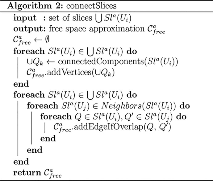 For each slice, the respective three-dimensional
representation Sla(Ui) might have multiple connected
components. To find
them, we abstract each Sla(Ui)—which, as
we explained, is a union of three-dimensional balls—as a graph
in which nodes correspond to balls and edges are added if two balls
overlap. We then perform a depth-first search in this graph to find
the connected components of Sla(Ui) (see our
previous work19 for a more detailed explanation).
As a result, we obtain a set of connected components {Qk} of the slice approximation Sla(Ui). These connected components are then abstracted
as vertices in the graph representation of the entire six-dimensional
configuration space,
  .
.
We proceed as follows: if two orientation neighborhoods Ui, Uj ⊂ SO(3) overlap—i.e.,
if Sla(Uj) ∈ Neighbors(Sla(Ui))—we look at the three-dimensional
representations Sla(Ui) and Sla(Uj) of the respective slices  and
and  . If two connected components Q ∈ Sla(Ui) and Q′
∈ Sla(Uj) of two neighboring slices Sla(Ui) and Sla(Uj) overlap, then these
three-dimensional connected components Q and Q′ represent parts of the entire six-dimensional
configuration space that can be connected by a path. As each of the
components consists of a collection of finite and infinite balls,
two components overlap if at least two balls belonging to different
components overlap. In this case, we add an edge between the nodes
corresponding to Q and Q′
in the graph of
  .
.
Once the graph representation is computed, we check whether
the
free space of a guest molecule has any bounded connected components
(see Algorithm 3). 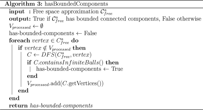 For this, we perform a depth-first search
(DFS) to find
the connected components of
  and see which ones are bounded (i.e., do
not contain infinite balls). In order to find connected components,
we start with the first vertex and continue until all of the vertices
are marked as processed. If there are bounded connected components,
then a pair of molecules under consideration is a caging complex,
i.e., the host molecule does not allow the guest to escape when the
latter is located inside.
5.4. Overall Process
Now that we have
described the crucial parts of the algorithm, we can summarize the
entire process (see Algorithm 4). 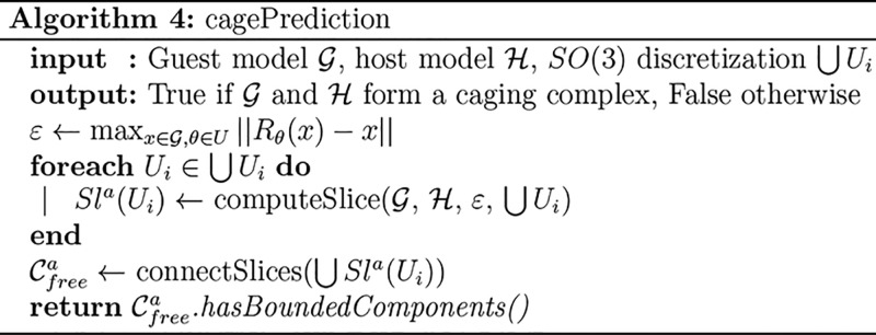 The algorithm takes as input
the models of the guest and
host and a discretized representation of SO(3). On
the basis of this grid, we compute the required minimal ε. For
each orientation neighborhood Ui, we compute the corresponding slice approximation Sla(Ui). Then we connect the slices and obtain an approximation
of the free space
  . Finally, we compute its connected components
and check whether there exist bounded connected components. If so,
we conclude that the pair of molecules form a caging complex.
5.5. Robustness of the Results
As discussed above, the proposed algorithm offers provable guarantees for the discovered caging complexes, provided that the underlying structural models are adequate. If it reports that two given molecules form a caging complex, the result holds only for the specific conformations that are supplied to the algorithm and might change if slight modifications to the input are made. Since the algorithm works with static molecular geometries, in the present section we consider the modeling assumptions that are related to the representation of a single molecular conformation as a set of balls (see section 4.1), i.e., coordinates of the centers and values of the radii.
The centers of the balls represent the positions of atomic nuclei, which can be obtained either from computational modeling or crystallographic data. Both methods provide atomic positions xi accompanied by certain confidence intervals xi ± Δxi. Inaccuracies in the positions are caused both by limitations of the method (i.e., crystal imperfection, theoretical models) and by thermal vibrations. To account for these uncertainties within the rigid-body model, let us first take a single ball ω with radius r and assume its center lies within a confidence interval x ± Δx. Then let us consider all balls ω̃j with radius r whose centers lie within x ± Δx and use their intersection ω′ = ∩ω̃j as a conservative approximation of a geometric representation of an atom (see Figure 8a). Conveniently, ω′ is simply a ball with center x and radius r – Δx.
Figure 8.
(a) Conservative approximation of a ball whose center can lie within a certain neighborhood as a ball with a reduced radius. (b) Illustration of the ball “reduction” on a water molecule model represented as three balls (red, oxygen; gray, hydrogen).
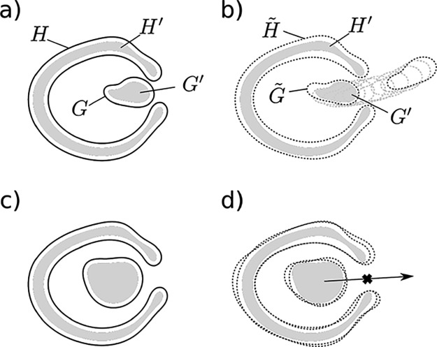
This approach allows us to model an atom with uncertainty in its position as a ball with a reduced radius. In other words, this “reduction” of all balls of the molecular model ensures that the resulting object will be fully contained in the original object (see Figure 8b), independent of the exact positions of the balls composing it. This conclusion is important for retaining the correctness of the algorithm: if the reduced model cannot escape, then the initial molecular model cannot escape either (Figure 9c,d). In contrast, if the reduced model is not caged, we cannot guarantee that the original model is not caged (Figure 9a,b). Therefore, by accounting for the uncertainty in the atomic coordinates through the reduction of the balls’ radii, we maintain the theoretical guarantees provided by the algorithm.
Figure 9.
(a) The host (H), the guest (G), and their “reduced” derivatives (H′ and G′); G′ is not caged by H′. (b) When G′ is not caged by H′, there might exist some host (H̃) and guest (G̃) models obtained from H and G by the constrained shift of their balls such that G̃ is not caged by H̃. (c, d) Same as (a, b) except that G′ is caged by H′; in this case, any G̃ is also caged by H̃.
Unlike the centers of the balls, which represent a real physical property, namely, the positions of atoms, the radii of the balls model only intermolecular interactions. Van der Waals radii do not define strict boundaries of atoms, meaning that an interval of rvdW values would be a more realistic model than just a single value. In particular, we would like to know whether the result obtained from the algorithm (two molecules form a caging complex) holds at higher or lower values of van der Waals radii rvdW = rvdW0 ± Δr. This can be realized by increasing or decreasing the balls’ radii by Δr.
From a computational point of view, the algorithm uses the balls’ radii only to identify intersections between host balls and guest balls using the trivial equation ∥x1 – x2∥ ≤ r1 + r2, where x and r are balls’ coordinates and radii, respectively. Since the right side of this equation always contains a sum of two radii, one from the host model and another from the guest model, it does not matter which model’s balls are reduced as long as the sum of the reductions is preserved. In other words, from the geometric point of view, changing the host model’s balls by rh and the guest model’s balls by rg is equivalent to changing either model’s balls by rh + rg.
In this way, a simple change of the balls’ radii allows us to account for the aforementioned disadvantages of the “solid sphere model”. This approach improves the applicability of the proposed algorithm, and it is generally useful for the estimation of the “robustness” of its results. For example, some caging complexes that can be discovered by the algorithm might disappear (i.e., become reported as not forming a caging complex) upon small changes in the input geometries (see Figure 10, top). Let us call these caging complexes “weak with threshold Δr” and the rest of the cages “strong with threshold Δr”. Here Δr is a subjective parameter that can be selected on the basis of, for example, uncertainties in the input geometries. The distinction between weak and strong cages becomes useful when discovered cages are to be reproduced experimentally. Under experimental conditions, molecular geometries can be slightly different, and modeling of intermolecular interactions as geometric collisions is not perfect. Caging complexes that are predicted to be “strong” have higher chances to be caging complexes in a real experiment. Here we do not set any specific threshold for the complex “weakness”, allowing it to be a variable parameter. Instead, for a caging complex formed by a host H and a guest G we define as the threshold the value of Δr such that if all of the radii of H and G are increased or decreased by Δr, H and G still form a caging complex.
Figure 10.
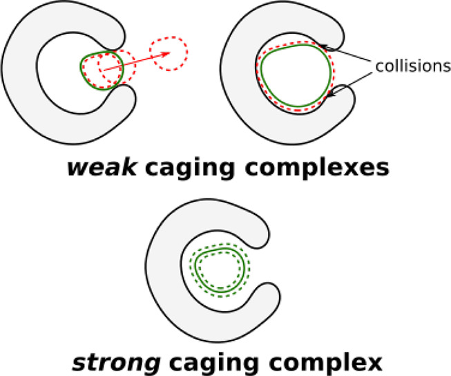
(top) A guest that might escape (left) or not fit (right) the host cavity upon small distortion of its geometry is reported as forming a weak caging complex with the host. (bottom) A guest that remains caged upon small distortion of its geometry is reported as forming a strong caging complex with the host.
6. Experimental Results
In order to demonstrate the algorithm operation, we ran three sets of computational experiments (see the Supporting Information for implementation details). First, caging complexes with monatomic guests that were discovered computationally in previous studies27,33 were analyzed. Then several host–guest pairs that were previously studied in laboratory experiments were considered. Finally, screening of a number of reported shape-persistent hosts and guests was performed in an effort to predict new complexes.
6.1. Algorithm Validation
6.1.1. Spherical Guests
As mentioned in section 2.1, existing approaches for the computational discovery of caging complexes can be used only with guests possessing spherical symmetry. Although not formulated in terms of geometric caging, algorithms such as pyWINDOW report values of the PLD and LCD that can be used to identify complexes with spherical guests according to the following equation: PLD < 2r < LCD, where r is the radius of a guest.33 Similarly, our algorithm can be used to determine the PLD of a host as the minimum radius of a sphere that can be caged by the host. Such an analysis can be performed by multiple runs of the algorithm with different values of the radius. Since the primary feature and computational expense of our algorithm is geared toward handling guests with more than three degrees of freedom, it runs significantly faster with spherical guests (see the Supporting Information).
First, we consider five hosts previously used to evaluate other computational algorithms33 and compare the PLDs calculated using our algorithm to those reported for these algorithms (see Table 1). The obtained values are in good agreement, confirming that our algorithm can be used to identify pores using the conventional spherical probe approach.31 A comparison with the results published by Miklitz and Jelfs33 reveals that the values obtained with pyWINDOW are slightly larger than the actual window sizes. We almost completely eliminated these discrepancies by increasing the sampling frequency in pyWINDOW, which diminished its performance (see the Supporting Information).
Table 1. Comparison of PLD Values (in Å) Obtained by Various Algorithms; Host Structures and Exact Parameter Settings for Each Algorithm Can Be Found in the Supporting Information.
| host | this work | pyWINDOW33,a | Zeo++21 | circumcircle35 |
|---|---|---|---|---|
| CC3-1(47) | 3.63 | 3.63 (3.64b) | 3.66 | 3.63 |
| CB6(48) | 3.72 | 3.72 (3.73b) | 4.12 | 3.69 |
| IC2(49) | 7.86 | 7.87 (7.90b) | 7.89 | 7.70 |
| CCC(47) | 9.17 | 9.17 (9.17b) | 9.09 | 8.99 |
| C60 | 0.00c | 0.00 | 0.00 | 0.00 |
The PLD was estimated as the largest diameter of all windows found.
The value in parentheses is the one reported by Miklitz and Jelfs with default parameters.33
This molecule is a C60 fullerene, where carbon atoms form a dense shell with no opening window.
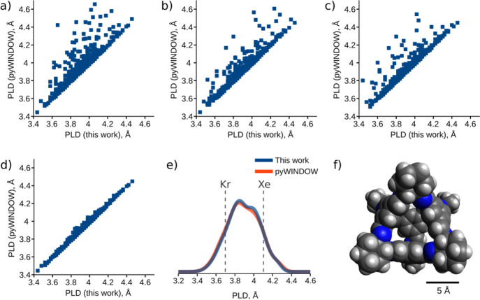
To investigate the applicability of our algorithm to an ensemble of host conformations, we analyzed MD trajectories of the covalent cage CC3(33) and compared our results with those produced by pyWINDOW for each trajectory frame. In this context, discrepancies between results could be mitigated by increasing the number of surrounding sphere sampling points in pyWINDOW from 250 to 6250 (see Figure 11a–c). However, in some cases, increasing the number of samples led to an increase in the detected PLDs. Because it is a sampling-based algorithm, pyWINDOW is sensitive to the orientation of the input geometry and thus requires several runs with random host orientation to find the best approximation of the PLD value. Running pyWINDOW with these considerations led to a good match to the results obtained by our algorithm (see Figure 11d). This highlights the advantages of our method, which is more precise and more computationally efficient, without any parametrization for single-sphere guests (see the Supporting Information for runtimes). The PLD distribution curves were also successfully reproduced (see Figure 11e), rendering the analysis of multiple host conformations possible with our algorithm.
Figure 11.
(a–d) Comparison of 515 PLDs generated by our algorithm and pyWINDOW using (a) 250, (b) 1250, or (c) 6250 surrounding sphere samples. (d) Minimum of (a–c) runs for 10 random orientations for each host. (e) PLD distributions generated by our algorithm and pyWINDOW. The diameters of Kr and Xe (3.69 and 4.10 Å, respectively) are marked with vertical dashed lines. (f) Structure of CC3-1.
Both generating a PLD distribution and running our algorithm on spherical guests with Xe and Kr radii allow the prediction of the penetration dynamics for Xe and Kr in solid CC3. Only 66 out of 515 conformations (13%) cage Kr, while 451 out of 515 (88%) cage Xe. This indicates that Kr can penetrate the solid quickly and that the adsorption level should be low because of low matching with the cavity size. In contrast, Xe is not caged only ∼12% of the time, and therefore, the adsorption, which implies traveling between cage cavities, should be slow. At the same time, Xe is expected to fill most of the cages in the material, suggesting high adsorption levels over long times. These conclusions are well-supported by experimental results.13
6.1.2. Guests of Arbitrary Shape
The capability of hosts to exhibit selectivity toward guest molecules on the basis of their shapes was first demonstrated in a breakthrough work by Mitra et al.12 In their study, organic hosts in the solid state were tested for the adsorption of several gaseous alkylbenzenes of similar size with different shapes. Crystallization from solutions containing the host and an excess amount of the guest molecules yielded caging complexes with the guest molecules trapped inside the host cavity, thus providing experimental evidence concerning whether the guest fits inside the host cavity (see section 2.1). When these crystals were redissolved in pure solvent, slow or fast guest release could be observed, providing an answer to the question of whether the guest could escape from the cavity. By combining these two answers, the authors were able to determine which pairs form caging complexes.
To validate our algorithm on the experimentally discovered caging complexes and noncomplexes, we aimed to reproduce key results on molecular shape sorting.12 We tested our algorithm on three pairs of molecules described in that study: the host CC3 and three guests. First, we evaluated our algorithm on a single conformation of CC3 derived from its crystal structure. Then an additional analysis of 515 host conformations simulated by MD was performed. In both cases we obtained results that are consistent with reported ones (see Figure 12). More precisely, we considered the following pairs:
CC3 and mesitylene (Mes). Our algorithm reports this pair to form a caging complex, and this result holds with a threshold of 0.3 Å (vide infra). This result is in full agreement with the solid-state, solution, and gas-phase studies by Mitra et al.,12 which showed that Mes was either caged inside CC3 (when crystallized together and then exposed to the solution) or, if introduced after CC3 synthesis, did not enter the cavity at all.
CC3 and 4-ethyltoluene (4ET). Unlike the previous pair, CC3 and 4ET are not predicted to form a caging complex, and this result holds with a threshold of 0.3 Å. Since our algorithm is designed to give a conservative estimate of complex prediction, this does not guarantee that CC3 and 4ETdo not form a complex but rather gives a hint that this pair is unlikely to be a caging complex. Indeed, this conclusion is supported by the experimental studies, in which 4ET was found to both fit inside the cavity of CC3 and escape it easily.
CC3 and m-xylene (mX). This pair of molecules is found to form a caging complex, but this result does not hold upon decrease of the radii by 0.3 Å, meaning that mX is likely to fit the cavity but might escape it easily. This is consistent with the experimentally observed crystals containing mX inside the CC3 cavity, from which m-xylene escaped upon dissolution (which amplified the cage flexibility).
Figure 12.
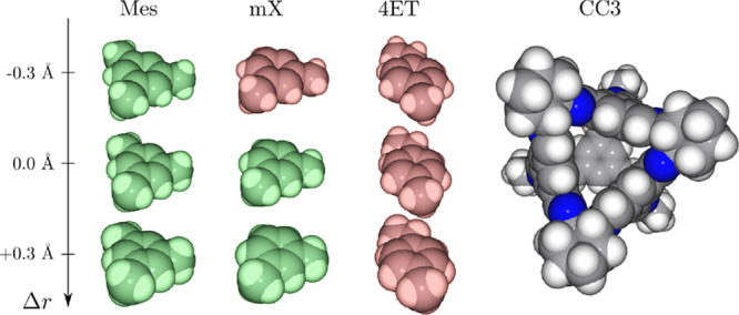
Illustration of the caging complex prediction results. 4-Ethyltoluene (4ET) is not caged by CC3; mesitylene (Mes) and m-xylene (mX) are caged by CC3. The robustness of all results (see section 5.5) was evaluated by varying the radii of the balls composing the guest models (±0.3 Å). Guest models that are caged by CC3 are depicted in green; those that escape the cage are depicted in red.
Although crystal structures show the genuine placement of atoms in a solid, they represent a single set of atomic positions, averaged over the entire crystal. In reality, host molecules adopt various conformations that are also subjected to thermal vibrations. One way to account for this without considering all of the conformations separately is the aforementioned reduction of radii. In these experiments, we estimated the variability of atomic positions composing the host and guest by their corresponding root-mean-square deviations obtained from solid-state MD simulations (0.25 Å for CC3 and 0.05 Å for all guests; see the Supporting Information). Although this way of accounting for differences in conformations is simplified and is applicable only to relatively rigid hosts and guests (with atomic displacements significantly smaller than the corresponding van der Waals radii), it allows an analysis to be performed at low computational cost and can thus be used for high-throughput screening.
To fully account for the flexibility of the CC3 host, we considered its 515 solid-state conformations (i.e., snapshots of its molecular dynamics trajectory33) and we ran our algorithm on each one of them. We found that 499 out of 515 conformations (97%) cage Mes, in accordance with experimental evidence; 293 out of 515 conformations (57%) cage mX, confirming that it can escape the host cavity in nearly half of the cases; and only 175 out of 515 conformations (34%) cage 4ET, which is reflected by experimental results showing it can travel through the host windows easily (see Figure 13). The seemingly large number of reported caging complexes for mX and 4ET is due to a certain number of “deflated” conformations. In contrast, the high percentage for Mes indicates that it is also caged by a significant number of “inflated” conformations—a feature of Mes being caged by CC3 as a result of shape rather than size selectivity.12 In addition, all of the guests were found to be caged by some conformation of CC3, meaning that they all fit inside the cavity; on the other hand, Mes and 4ET can escape through the host windows, as proposed by Mitra et al.12
Figure 13.
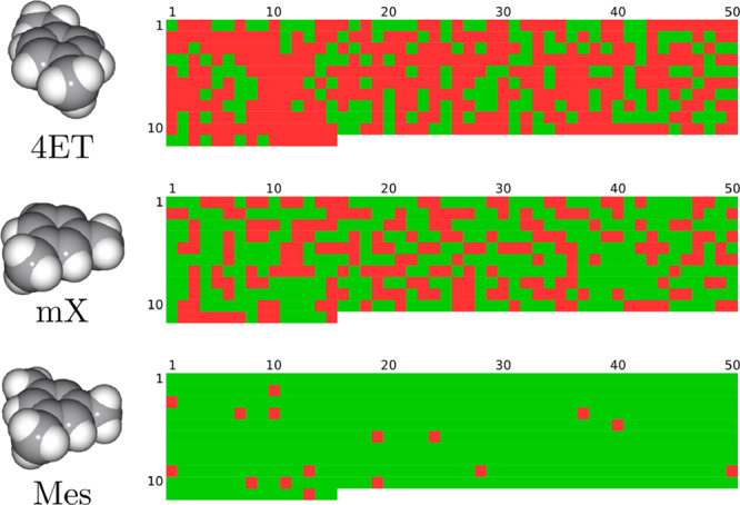
Illustration of the caging prediction results. Each colored square corresponds to a single algorithm run with one of CC3 conformations. Color code: green, caging complex; red, not a caging complex. Conformations were obtained from a molecular dynamics trajectory (see the Supporting Information; the conformation index can be obtained with the following formula: i = row·50 + column – 50).
6.2. Prediction of New Caging Complexes
A potential application of the present work is the prediction of new caging complexes. As host synthesis is a time-consuming process, computational prediction and screening is the most feasible strategy for the development of new caging complexes. In this section, we report the use of our algorithm to search for new complexes that are not described in the literature. In particular, we aimed to answer the following question: “which hosts can exhibit selectivity in the caging of several guests with similar shape?” For illustrative purposes, we selected four guests—monohalobenzenes with close molecular volumes50 and similar shapes: fluoro- (FB), chloro- (CB), bromo- (BB), and iodobenzene (IB). The hosts belong to a set of 46 shape-persistent molecules with cavities (CDB46), a modified version of the CDB41 database27 (see the Supporting Information). Since several crystal structures are available for hosts CC1, CC3, and CC4, all of them are included. Each result is evaluated for its sensitivity to the input geometry using a threshold of 0.3 Å, as in section 6.1.2.
In the screening process, we ran our algorithm on all 184 host–guest pairs and discovered 20 strong caging complexes and 38 weak complexes (see Figure 14). Among the strong ones, 16 out of 20 were formed by four hosts—RCC3b, CB6, WC2, and WC3—with all four guests. Interestingly, a single bounded connected component was found in the RCC3b–FB pair, while in the pairs formed by RCC3b with CB, BB, and IB, four bounded connected components were detected. This result is due to the hampered rotation of the guests: large halogen atoms prevent the molecule from rotating freely inside the cavity, producing four different alignments of the guest molecule due to the tetrahedral symmetry of the host cavity (see Figure 15). In contrast, the smaller fluorine atom in FB is small enough to allow for free rotation. Such information could be utilized in the rational design of caging complexes and the fine-tuning of existing complexes by small modifications of the guests.
Figure 14.
Results of the screening of 184 host–guest pairs: s, strong caging complex; w, weak complex; n, not a complex. Only hosts that were found to form at least one caging complex are shown; the complete table is given in the Supporting Information.
Figure 15.
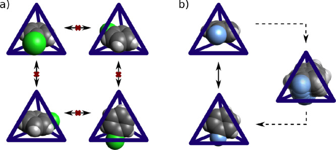
Illustration of (a) the restricted intercavity rotation of CB and (b) the free rotation of FB.
Apart from RCC3b, three other hosts cage all four guests: CB6, WC2, and WC3. It is noteworthy that these hosts are reported to have small internal cavity volumes of 36, 52, and 59 Å3,27 while the molecular volume of the smallest guest, fluorobenzene, is 88 Å3.50 This discrepancy emphasizes the importance of using our algorithm for hosts with arbitrary cavity shapes. Previous work defined the cavity size as the LCD,17 which is generally applicable only to hosts with nearly spherical cavities and to monatomic guests.27
Our results show that only four other hosts (CC3-1, CC3-5, WC4, and NC1) form strong caging complexes, all with FB (see Figure 14), suggesting that their cavities are too small to fit bigger guests. Among all 46 hosts, only WC4 produces all three possible outcomes: a strong complex (with FB), a weak complex (with CB and BB), and not a complex (with IB). This feature may render WC4 a good candidate for the separation of halobenzenes.
This experiment demonstrates that our algorithm is capable of handling various hosts. Moreover, this algorithm is conservative (see section 5), meaning that it might not report certain caging complexes because of the overapproximation of the free space of the guest. Theoretically, this could result in a very low rate of detected complexes. However, the results obtained in this section indicate otherwise, highlighting the applicability of our approach.
7. Discussion
As demonstrated above, the present approach is remarkably useful for molecular caging prediction with hosts and guests of arbitrary shape. Given the theoretical guarantees of our algorithm, the only limitation of its practical applicability is the representation of molecules as rigid bodies composed of balls. As previously stated, such representation consists of molecular geometry and modeling of intermolecular interactions as intersections of geometric objects. Luckily, a number of limitations, such as thermal vibrations and imperfect values of van der Waals radii, can be taken into account within the same model (see section 5.5).
The present method, when combined with conformational analysis, can be easily applied to the analysis of both hosts with low levels of structural rigidity and guests with internal rotational degrees of freedom. Results obtained for different conformations can be analyzed using statistical methods. Such an approach was first illustrated by Miklitz et al.,27 who generated a number of host conformations and ran a corresponding spherical guest caging algorithm for each one. In this work, we successfully used this method with nonspherical guests. Sometimes uncertainty in the host conformation can be solved by conservative estimation. For example, if the cage can “inflate”,51 then an “inflated” conformation with bigger escape windows can be used.
The core of our approach—reduction of the dimensionality in the analysis of the configuration space of a molecule—allows for the extension of our algorithm beyond geometric analysis. The definition of a caging complex in geometric terms (when the guest molecule is caged for purely steric reasons) can be revised by considering chemical interactions, a standard approach in biomolecular interactions modeling.52 Usually, molecules at equilibrium are located at a local minimum E = E0 on the potential energy surface (PES) and can move on it without exceeding a certain small barrier ΔE (typically defined by the temperature). Thus, the condition of a collision in the definition of the configuration space can be replaced by the condition E ≥ E0 + ΔE. From the computational point of view, this approach can be formulated as an energy-bounded caging problem,53 i.e., caging with respect to an energy field. We are therefore interested in developing our approach in this direction in the future.
8. Conclusions
In this paper, we have proposed a screening algorithm that predicts whether two given molecules form a caging complex. Our approach, based on the approximation of a six-dimensional configuration space that was originally developed for robotic applications, allowed us to extend the toolbox of cage prediction, which was previously limited to monatomic guests. Our method successfully reproduced the experimentally discovered phenomenon of molecular shape sorting. The algorithm also proved to be efficient in a computational screening of potential cage candidates, finding 20 strong cages among 184 analyzed pairs. The generality of the selected molecular representation allows the present method to be used in the analysis of any molecular system with a well-defined structure, including organic cages, protein cages, covalent and metal–organic frameworks, etc.
Acknowledgments
This work was supported in part by the Knut and Alice Wallenberg Foundation and Rice University Funds.
Supporting Information Available
The Supporting Information is available free of charge at https://pubs.acs.org/doi/10.1021/acs.jcim.9b00945.
Author Contributions
⊥ O.K. and A.V. contributed equally to this work.
The authors declare no competing financial interest.
Supplementary Material
References
- Chichak K. S.; Cantrill S. J.; Pease A. R.; Chiu S.-H.; Cave G. W. V.; Atwood J. L.; Stoddart J. F. Molecular Borromean Rings. Science 2004, 304, 1308–1312. 10.1126/science.1096914. [DOI] [PubMed] [Google Scholar]
- Hasell T.; Cooper A. I. Porous Organic Cages: Soluble, Modular and Molecular Pores. Nat. Rev. Mater. 2016, 1, 16053. 10.1038/natrevmats.2016.53. [DOI] [Google Scholar]
- Cram D. J. Cavitands: Organic Hosts with Enforced Cavities. Science 1983, 219, 1177–1183. 10.1126/science.219.4589.1177. [DOI] [PubMed] [Google Scholar]
- Deraedt C.; Astruc D. Supramolecular Nanoreactors for Catalysis. Coord. Chem. Rev. 2016, 324, 106–122. 10.1016/j.ccr.2016.07.007. [DOI] [Google Scholar]
- Mastalerz M. Shape-Persistent Organic Cage Compounds by Dynamic Covalent Bond Formation. Angew. Chem., Int. Ed. 2010, 49, 5042–5053. 10.1002/anie.201000443. [DOI] [PubMed] [Google Scholar]
- Han M.; Michel R.; He B.; Chen Y.-S.; Stalke D.; John M.; Clever G. H. Light-Triggered Guest Uptake and Release by a Photochromic Coordination Cage. Angew. Chem., Int. Ed. 2013, 52, 1319–1323. 10.1002/anie.201207373. [DOI] [PubMed] [Google Scholar]
- Croué V.; Goeb S.; Szalóki G.; Allain M.; Sallé M. Reversible Guest Uptake/Release by Redox-Controlled Assembly/Disassembly of a Coordination Cage. Angew. Chem., Int. Ed. 2016, 55, 1746–1750. 10.1002/anie.201509265. [DOI] [PubMed] [Google Scholar]
- Bhaskar S.; Lim S. Engineering Protein Nanocages as Carriers for Biomedical Applications. NPG Asia Mater. 2017, 9, e371 10.1038/am.2016.128. [DOI] [PMC free article] [PubMed] [Google Scholar]
- Ahmad N.; Younus H. A.; Chughtai A. H.; Verpoort F. Metal-Organic Molecular Cages: Applications of Biochemical Implications. Chem. Soc. Rev. 2015, 44, 9–25. 10.1039/C4CS00222A. [DOI] [PubMed] [Google Scholar]
- Therrien B. Drug Delivery by Water-Soluble Organometallic Cages. Top. Curr. Chem. 2011, 319, 35–55. 10.1007/128_2011_272. [DOI] [PubMed] [Google Scholar]
- Deshayes S.; Gref R. Synthetic and Bioinspired Cage Nanoparticles for Drug Delivery. Nanomedicine 2014, 9, 1545–1564. 10.2217/nnm.14.67. [DOI] [PubMed] [Google Scholar]
- Mitra T.; Jelfs K. E.; Schmidtmann M.; Ahmed A.; Chong S. Y.; Adams D. J.; Cooper A. I. Molecular Shape Sorting Using Molecular Organic Cages. Nat. Chem. 2013, 5, 276–281. 10.1038/nchem.1550. [DOI] [PubMed] [Google Scholar]
- Chen L.; et al. Separation of Rare Gases, Chiral Molecules by Selective Binding in Porous Organic Cages. Nat. Mater. 2014, 13, 954–960. 10.1038/nmat4035. [DOI] [PubMed] [Google Scholar]
- Mastalerz M. Porous Shape-Persistent Organic Cage Compounds of Different Size, Geometry, and Function. Acc. Chem. Res. 2018, 51, 2411–2422. 10.1021/acs.accounts.8b00298. [DOI] [PubMed] [Google Scholar]
- Tozawa T.; et al. Porous Organic Cages. Nat. Mater. 2009, 8, 973–978. 10.1038/nmat2545. [DOI] [PubMed] [Google Scholar]
- Greenaway R. L.; Santolini V.; Bennison M. J.; Alston B. M.; Pugh C. J.; Little M. A.; Miklitz M.; Eden-Rump E. G. B.; Clowes R.; Shakil A.; Cuthbertson H. J.; Armstrong H.; Briggs M. E.; Jelfs K. E.; Cooper A. I. High-throughput Discovery of Organic Cages and Catenanes Using Computational Screening Fused with Robotic Synthesis. Nat. Commun. 2018, 9, 2849. 10.1038/s41467-018-05271-9. [DOI] [PMC free article] [PubMed] [Google Scholar]
- Turcani L.; Greenaway R. L.; Jelfs K. E. Machine Learning for Organic Cage Property Prediction. Chem. Mater. 2019, 31, 714–727. 10.1021/acs.chemmater.8b03572. [DOI] [Google Scholar]
- Varava A.; Carvalho J. F.; Pokorny F. T.; Kragic D.. Caging and Path Non-Existence: A Deterministic Sampling-Based Verification Algorithm. Presented at the International Symposium on Robotics Research, 2017.
- Varava A.; Carvalho J. F.; Pokorny F. T.; Kragic D.. Free Space of Rigid Objects: Caging, Path Non-Existence, and Narrow Passage Detection. Presented at the Workshop on the Algorithmic Foundations of Robotics, 2018.
- Makita S.; Wan W. A Survey of Robotic Caging and Its Applications. Adv. Rob. 2017, 31, 1071–1085. 10.1080/01691864.2017.1371075. [DOI] [Google Scholar]
- Willems T. F.; Rycroft C. H.; Kazi M.; Meza J. C.; Haranczyk M. Algorithms and Tools for High-Throughput Geometry-Based Analysis of Crystalline Porous Materials. Microporous Mesoporous Mater. 2012, 149, 134–141. 10.1016/j.micromeso.2011.08.020. [DOI] [Google Scholar]
- Li Y.; Li X.; Liu J.; Duan F.; Yu J. In Silico Prediction and Screening of Modular Crystal Structures via a High-Throughput Genomic Approach. Nat. Commun. 2015, 6, 8328. 10.1038/ncomms9328. [DOI] [PMC free article] [PubMed] [Google Scholar]
- Shehu A.; Plaku E. A Survey of Computational Treatments of Biomolecules by Robotics-Inspired Methods Modeling Equilibrium Structure and Dynamic. Journal of Artificial Intelligence Research 2016, 57, 509–572. 10.1613/jair.5040. [DOI] [Google Scholar]
- Devaurs D.; Bouard L.; Vaisset M.; Zanon C.; Al-Bluwi I.; Iehl R.; Siméon T.; Cortés J. MoMA-LigPath: a Web Server to Simulate Protein–Ligand Unbinding. Nucleic Acids Res. 2013, 41, W297–W302. 10.1093/nar/gkt380. [DOI] [PMC free article] [PubMed] [Google Scholar]
- Giri N.; Del Pópolo M. G.; Melaugh G.; Greenaway R. L.; Rätzke K.; Koschine T.; Pison L.; Gomes M. F. C.; Cooper A. I.; James S. L. Liquids with Permanent Porosity. Nature 2015, 527, 216. 10.1038/nature16072. [DOI] [PubMed] [Google Scholar]
- Jelfs K. E.; Wu X.; Schmidtmann M.; Jones J. T. A.; Warren J. E.; Adams D. J.; Cooper A. I. Large Self-Assembled Chiral Organic Cages: Synthesis, Structure, and Shape Persistence. Angew. Chem. 2011, 123, 10841–10844. 10.1002/ange.201105104. [DOI] [PubMed] [Google Scholar]
- Miklitz M.; Jiang S.; Clowes R.; Briggs M. E.; Cooper A. I.; Jelfs K. E. Computational Screening of Porous Organic Molecules for Xenon/Krypton Separation. J. Phys. Chem. C 2017, 121, 15211–15222. 10.1021/acs.jpcc.7b03848. [DOI] [Google Scholar]
- Li H.; Laine A.; O’Keeffe M.; Yaghi O. M. Supertetrahedral Sulfide Crystals with Giant Cavities and Channels. Science 1999, 283, 1145–1147. 10.1126/science.283.5405.1145. [DOI] [PubMed] [Google Scholar]
- Haldoupis E.; Nair S.; Sholl D. S. Efficient Calculation of Diffusion Limitations in Metal Organic Framework Materials: A Tool for Identifying Materials for Kinetic Separations. J. Am. Chem. Soc. 2010, 132, 7528–7539. 10.1021/ja1023699. [DOI] [PubMed] [Google Scholar]
- Sikora B. J.; Wilmer C. E.; Greenfield M. L.; Snurr R. Q. Thermodynamic Analysis of Xe/Kr Selectivity in over 137000 Hypothetical Metal-Organic Frameworks. Chem. Sci. 2012, 3, 2217–2223. 10.1039/c2sc01097f. [DOI] [Google Scholar]
- Colón Y. J.; Snurr R. Q. High-Throughput Computational Screening of Metal-Organic Frameworks. Chem. Soc. Rev. 2014, 43, 5735–5749. 10.1039/C4CS00070F. [DOI] [PubMed] [Google Scholar]
- Pinheiro M.; Martin R. L.; Rycroft C. H.; Haranczyk M. High Accuracy Geometric Analysis of Crystalline Porous Materials. CrystEngComm 2013, 15, 7531–7538. 10.1039/c3ce41057a. [DOI] [Google Scholar]
- Miklitz M.; Jelfs K. E. pywindow: Automated Structural Analysis of Molecular Pores. J. Chem. Inf. Model. 2018, 58, 2387–2391. 10.1021/acs.jcim.8b00490. [DOI] [PMC free article] [PubMed] [Google Scholar]
- Düren T.; Bae Y.-S.; Snurr R. Q. Using Molecular Simulation to Characterise Metal-Organic Frameworks for Adsorption Applications. Chem. Soc. Rev. 2009, 38, 1237–1247. 10.1039/b803498m. [DOI] [PubMed] [Google Scholar]
- Holden D.; Jelfs K. E.; Cooper A. I.; Trewin A.; Willock D. J. Bespoke Force Field for Simulating the Molecular Dynamics of Porous Organic Cages. J. Phys. Chem. C 2012, 116, 16639–16651. 10.1021/jp305129w. [DOI] [Google Scholar]
- Watanabe T.; Sholl D. S. Accelerating Applications of Metal-Organic Frameworks for Gas Adsorption and Separation by Computational Screening of Materials. Langmuir 2012, 28, 14114–14128. 10.1021/la301915s. [DOI] [PubMed] [Google Scholar]
- Sturluson A.; Huynh M. T.; York A. H. P.; Simon C. M. Eigencages: Learning a Latent Space of Porous Cage Molecules. ACS Cent. Sci. 2018, 4, 1663–1676. 10.1021/acscentsci.8b00638. [DOI] [PMC free article] [PubMed] [Google Scholar]
- Bárcia P. S.; Guimarães D.; Mendes P. A.; Silva J. A.; Guillerm V.; Chevreau H.; Serre C.; Rodrigues A. E. Reverse Shape Selectivity in the Adsorption of Hexane and Xylene Isomers in MOF UiO-66. Microporous Mesoporous Mater. 2011, 139, 67–73. 10.1016/j.micromeso.2010.10.019. [DOI] [Google Scholar]
- Rodriguez A.; Mason M. T.; Ferry S. From Caging to Grasping. Int. J. Rob. Res. 2012, 31, 886–900. 10.1177/0278364912442972. [DOI] [Google Scholar]
- Pereira G. A. S.; Kumar V.; Spletzer J. R.; Taylor C. J.; Campos M. F. M.. Cooperative Transport of Planar Objects by Multiple Mobile Robots Using Object Closure. In Experimental Robotics VIII; Siciliano B., Dario P., Eds.; Springer, 2003; pp 287–296. [Google Scholar]
- Pereira G. A.; Campos M. F.; Kumar V. Decentralized Algorithms for Multi-Robot Manipulation via Caging. Int. J. Rob. Res. 2004, 23, 783–795. 10.1177/0278364904045477. [DOI] [Google Scholar]
- Leach A.Molecular Modelling: Principles and Applications; Prentice Hall, 2001; p 7. [Google Scholar]
- Bondi A. van der Waals Volumes and Radii. J. Phys. Chem. 1964, 68, 441–451. 10.1021/j100785a001. [DOI] [Google Scholar]
- Rowland R. S.; Taylor R. Intermolecular Nonbonded Contact Distances in Organic Crystal Structures: Comparison with Distances Expected from van der Waals Radii. J. Phys. Chem. 1996, 100, 7384–7391. 10.1021/jp953141+. [DOI] [Google Scholar]
- Yershova A.; Jain S.; Lavalle S. M.; Mitchell J. C. Generating Uniform Incremental Grids on SO(3) Using the Hopf Fibration. Int. J. Rob. Res. 2010, 29, 801–812. 10.1177/0278364909352700. [DOI] [PMC free article] [PubMed] [Google Scholar]
- Edelsbrunner H. Deformable Smooth Surface Design. Discrete Comp. Geom. 1999, 21, 87–115. 10.1007/PL00009412. [DOI] [Google Scholar]
- Skowronek P.; Warzajtis B.; Rychlewska U.; Gawroński J. Self-Assembly of a Covalent Organic Cage with Exceptionally Large and Symmetrical Interior Cavity: the Role of Entropy of Symmetry. Chem. Commun. 2013, 49, 2524–2526. 10.1039/c3cc39098e. [DOI] [PubMed] [Google Scholar]
- Bardelang D.; Udachin K. A.; Leek D. M.; Margeson J. C.; Chan G.; Ratcliffe C. I.; Ripmeester J. A. Cucurbit[n]urils (n = 58): A Comprehensive Solid State Study. Cryst. Growth Des. 2011, 11, 5598–5614. 10.1021/cg201173j. [DOI] [Google Scholar]
- Matsui K.; Segawa Y.; Itami K. All-Benzene Carbon Nanocages: Size-Selective Synthesis, Photophysical Properties, and Crystal Structure. J. Am. Chem. Soc. 2014, 136, 16452–16458. 10.1021/ja509880v. [DOI] [PubMed] [Google Scholar]; PMID: 25361385.
- Atwood J.; Steed J.. Encyclopedia of Supramolecular Chemistry; Dekker Encyclopedias Series, Vol. 1; Marcel Dekker, 2004; p 450. [Google Scholar]
- Santolini V.; Miklitz M.; Berardo E.; Jelfs K. E. Topological Landscapes of Porous Organic Cages. Nanoscale 2017, 9, 5280–5298. 10.1039/C7NR00703E. [DOI] [PubMed] [Google Scholar]
- Dasgupta B.; Liang J.. Geometric Models of Protein Structure and Function Prediction. In Models and Algorithms for Biomolecules and Molecular Networks; Wiley, 2016; Chapter 1, pp 1–28. [Google Scholar]
- Mahler J.; Pokorny F. T.; McCarthy Z.; van der Stappen A. F.; Goldberg K. Energy-Bounded Caging: Formal Definition and 2-D Energy Lower Bound Algorithm Based on Weighted Alpha Shapes. IEEE Robot. Autom. Lett. 2016, 1, 508–515. 10.1109/LRA.2016.2519145. [DOI] [Google Scholar]
- Varava A.; Kragic D.; Pokorny F. T. Caging Grasps of Rigid and Partially Deformable 3-D Objects With Double Fork and Neck Features. IEEE Trans. Robot. 2016, 32, 1479–1497. 10.1109/TRO.2016.2602374. [DOI] [Google Scholar]
Associated Data
This section collects any data citations, data availability statements, or supplementary materials included in this article.


