

Abstract
Electrodes based on organic matter operating in aqueous electrolytes enable new approaches and technologies for assembling and utilizing batteries that are difficult to achieve with traditional electrode materials. Here, we report how thiophene‐based trimeric structures with naphthoquinone or hydroquinone redox‐active pendent groups can be processed in solution, deposited, dried and subsequently polymerized in solid state to form conductive (redox) polymer layers without any additives. Such post‐deposition polymerization offers efficient use of material, high mass loading (up to 10 mg cm−2) and good flexibility in the choice of substrate and coating method. By employing these materials as anode and cathode in an acidic aqueous electrolyte a rocking‐chair proton battery is built. The battery shows good cycling stability (85 % after 500 cycles), withstands rapid charging, with full capacity (60 mAh g−1) reached within 100 seconds, allows for direct integration with photovoltaics, and retains its favorable characteristics even at −24 °C.
Keywords: conducting redox polymers, electrical energy storage, electrochemistry, organic battery, quinones
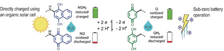
Combining naphthoquinone or hydroquinone redox‐active pendent groups, an all‐organic battery was designed to operate in aqueous electrolyte. This battery does not only show good capacity retention over 500 cycles but can also be charged ultra‐rapidly using a potential step, enabling easy integration with an organic solar cell.
Introduction
With a seemingly ever‐increasing demand for secondary electrical energy storage, research into how to utilize organic matter as the active material in batteries has exploded.1 Environmentally benign and more economical than conventional inorganic batteries,2 together with a wide structural variety and the possibility of tailoring their properties by chemical modification are some of the envisioned benefits of batteries based on redox‐active organic molecules.3 These could also allow new ways to assemble and utilize batteries, including bottom‐up synthesis, the use of environmentally benign and safe electrolytes based on water, the easy disposal of complete battery cells with regular household waste collection, the development of flexible batteries for wearable electronics and the development of super‐fast charging batteries.4
Batteries consisting of one organic and one inorganic electrode have been extensively studied with the aim of maximizing cell potential and investigating the characteristics of organic electrode materials.5 All‐organic batteries are rarer,6 but are gaining in popularity, as exemplified by the pioneering work of Nishide using organic radical batteries,7 and Poizot using lithiated tetrahydroxybenzoquinone.8 Recently, the work of Schubert's, Gaubicher's and Aziz's groups on all‐organic battery concepts has also shown promising results.9 There is a wide range of organic battery concepts, for example the organic electrode material can be either polymeric to prevent dissolution in the electrolyte, or consist of single molecules with very low solubility in the chosen electrolyte.4, 5c, 10 Electrolytes using metal ions (e.g. Li, Na, Mg ions), molecular ions (e.g. tetraalkyl ammonium), or protons (H+) have even been considered.3b, 9d, 11 Organic solvents are common but there are also examples using ionic liquid or aqueous electrolytes.9a, 12
The vast majority of these concepts requires significant amounts of conducting additives, often different forms of carbon, as most organic materials are insulators. Consequently, while the theoretical specific capacity of these battery materials might be high, the effective capacity is considerably lower (Supporting Information (SI) table S1). Moreover, a polymeric binder is often needed to ensure good adhesion and material cohesion. These insoluble additives complicate the solution processing of the electrode material, required for assembly techniques such as spray coating, screen printing, ink‐jet printing or dip coating.
Another approach to tackling these issues is to attach redox‐active groups to π‐conjugated structures, for example, thiophene or pyrrole, which upon polymerization form a conductive polymer (CP) backbone, resulting in so‐called conducting redox polymers (CRPs).11b, 13 CRPs require no additives as the CP backbone serves a dual purpose: i) to facilitate electron transport through the material while the redox‐active pendant stores the charge and ii) to reduce material solubility. Thus, the properties of the pendants determine battery characteristics such as storage capacity, voltage output, and available cycling chemistries. The CRP approach results in other challenges with respect to forming and processing the CPs.14 The traditional method of forming conductive polymers, through oxidative electropolymerization from a monomer solution, is unsatisfactory as it is difficult to scale and is limited to conducting substrates. Oxidative chemical polymerization is better for large scale synthesis.15 However, once the CP is formed, there is a strong tendency for aggregation through π–π stacking, which makes the polymer insoluble and hard to process further. The main strategies for overcoming this issue have been to engineer stable polymer suspensions, as with poly(3,4‐ethylenedioxythiophene):poly(styrenesulfonate) (PEDOT:PSS),16 or by chemically modifying the monomers with solubilizing groups.17 The first method has limited versatility and the second strategy limits further substitution of the monomer. Limited substitution also hinders the use of solid state polymerization methods developed for thiophene derivatives.18
This report discusses all‐organic batteries assembled from CRPs containing repeating terthiophene units, that is, trimers, allowing for what we call post‐deposition polymerization of the trimer layers. As opposed to previously reports on CRP batteries11b this approach allows easy processing as the soluble trimer can be solution‐processed and then, after drying, the layer can be polymerized in the solid state either by applying a positive potential to the layer in the presence of an electrolyte solution, or by dipping the layer into an oxidant solution. In addition to permitting traditional, up‐scalable layering techniques, this method achieves 100 % utilization of the precursor material thus minimizing material losses. We used benzoquinone/hydroquinone (Q/QH2) and naphthoquinone/naphthohydroquinone (NQ/NQH2) as capacity carriers in the two‐electron, two‐proton (2e2H) redox reaction. The use of naphtoquinone, instead of the previously reported anthraquinone unit in the CRP,11b allow us to use an acidic, aqueous electrolyte for the formation of a proton battery, where the protons function as charge carriers in a rocking‐chair motion upon charge and discharge (Figure 1). We have shown how such a battery can be charged in mere seconds using a constant‐voltage charging method, and that this type of charging is beneficial for the stability of the organic battery compared to conventional constant‐current charging. The battery can be charged directly by an organic solar cell, no additional electronics are needed, operates in sub‐zero temperatures and can be used to power for example, a thermometer.
Figure 1.
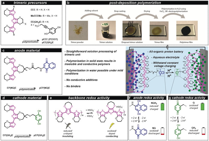
Schematic representation of the all‐organic battery concept, chemical structures/naming and polymerization method. The trimeric precursors (a) were used in the post‐deposition polymerization procedure (b) to form polymers with similar characteristics to those formed from monomeric units. In post‐deposition polymerization, the trimer is first dissolved in an organic electrolyte, followed by drop casting and drying. Subsequently, the trimer film is oxidized, either i) electrochemically in an aqueous 0.5 m H2SO4 solution by cyclic voltammetry between 0.0 and 1.21 V vs. SHE at 10 mV s−1 or by applying a potential of 0.81 V vs. SHE for 3000 s or ii) chemically by immersion into an acidic aqueous solution containing 1 m FeCl3 as oxidant, resulting in the formation of a black polymer layer. The anode material (c) consisted of pEP(NQ)E, which was formed by oxidative polymerization of EP(NQ)E. Similarly, the cathode material pEP(QH2)E (d) was formed from EP(QH2)E. Conductivity was achieved from a polythiophene backbone (e) that was oxidized/doped, for example, with HSO4 −. The battery (middle) was assembled as an all‐organic proton battery using 0.5 m H2SO4 (aq) electrolyte, which enabled a rocking‐chair motion of the protons. The anode and cathode redox activity relies on the two‐electron two‐proton (2e2 H) redox process of the pendants (f and g). When the battery is charged, the quinone pendant groups are in the Q and NQH2 states, for the positive electrode (cathode) and negative electrode (anode), respectively. During discharge, the active cathode material is converted to QH2 while the anode is converted to NQ. E=3,4‐ethylenedioxythiophene; NQ=naphthoquinone; NQH2=naphthohydroquinone; P=3,4‐propylenedioxythiophene; p=polymerized; Q=benzoquinone; QH2=hydroquinone.
Results and Discussion
Post‐deposition polymerization: We envisioned a method that would reliably and smoothly result in a CP regardless of the pendant group on the polymerizable unit. Crucially, we planned for polymerization to be initiated only after monomer deposition, rendering an insoluble polymer material immobilized on the substrate surface and containing only the desired dopant. Furthermore, polymerization should proceed under mild conditions and, importantly, without re‐dissolving the deposited material. To achieve this we decided to add an additional thiophene unit on both sides of a (functionalized) thiophene monomer, forming a terthiophene trimer which we believed could be conductive upon oxidation. This would allow polymerization to propagate through the trimer layer to yield CPs or CRPs. Oligomers would also exhibit lower oxidation potentials compared to the monomer, allowing for milder polymerization conditions.19 Indeed, while a monomeric 3,4‐ethylenedioxythiophene (EDOT, E) or a hydroquinone‐functionalized EDOT (EQH2) 20 does not accomplish these targets, utilizing a trimeric structure of thiophenes, EEE and EE(QH2)E does (SI section S1 for synthetic details and characterization). Polymerization was achieved in line with the approach detailed above. A solution of EEE or EE(QH2)E) was drop‐cast onto a conductive substrate and the solvent was removed under vacuum (Figure 1 b and SI section S1). The electrode was then submerged in 0.5 m aqueous H2SO4 solution, which does not dissolve the materials, and a potential was applied to the trimer layer using a cyclic voltammetry voltage profile. Monitoring the conductance in situ during the voltammetric sweeps revealed that the conductance started to increase sharply after a certain potential during the initial anodic polarization, that is, potential sweep from lower to higher voltages (SI Figure S20). Concurrently, the yellow/amber trimer layer became black. The conductance reached a plateau which remained during consecutive cycles, during both anodic and cathodic sweeps, with no substantial change in conductance over the potential interval 0.2–1 V vs. a standard hydrogen electrode (SHE). This is indicative of a CP and we interpreted the increase in conductance observed during the initial anodic sweep as polymerization of the trimeric layers. Using the same protocol with a methyl end‐capped trimer, MeEEEMe, which cannot form a conducting polymer, nevertheless revealed a small conductance increase upon oxidization (SI Figure S21). As hypothesized, the trimers are thus intrinsically conducting in oxidized state and post‐deposition polymerization was successful since oxidation, and concomitant polymerization, can propagate through the trimer layer by virtue of the inherent trimer conductance. Note, neither E nor EQH2 could be polymerized in this way, suggesting that the use of longer oligomers is essential for the post‐deposition polymerization approach. In addition, electrochemical characterization shows that the potential required to oxidize trimeric units is about 1 V below the oxidation potential for monomeric compounds allowing for the possibility to use water electrolytes during polymerization without risking electrolyte degradation and generation of reactive oxygen species (SI Figure S23). Consequently, we concluded that the lower oxidation potential and the finite conductivity of the trimer upon doping are essential for this method to work. The polymers produced, pEEE (i.e. PEDOT) and pEE(QH2)E, displayed similar characteristics to polymers formed through oxidative electropolymerization of EDOT (to PEDOT) and EQH2 (to pEQH2) (SI section S4).20, 21 Electrochemical quartz crystal microbalance (EQCM) during polymerization indicated that the polymers formed were short (nine thiophenes long on average), in line with previous studies on PEDOT which found between 5 and 20 units22 (SI section S4).
All‐organic batteries: Confident of the applicability of post‐deposition polymerization, we designed a new set of trimers based on a central quinone‐functionalized 3,4‐propylenedioxythiophene (ProDOT, P) to which two EDOTs (E) were attached at the α‐positions to form an EPE trimer. Synthetic availability and reduced complexity of the trimer and polymer due to the lack of chirality of the functionalized ProDOT were the main rationales behind this modification. A hydroquinone (QH2) or naphthoquinone (NQ) capacity carrier was attached as a pendant group to the central ProDOT, forming EP(QH2)E and EP(NQ)E, respectively (see SI section S2 for synthetic details and full characterization). These trimers were subsequently polymerized to form the redox‐active electrode materials pEP(QH2)E and pEP(NQ)E employed as cathode (positive electrode) and anode (negative electrode), respectively. Note, for simplicity we refer to the polymers in their discharged state [(pEP(QH2)E and pEP(NQ)E)] when discussing these in general terms. A constant potential polymerization (0.81 V vs. SHE for 3000 s) was used to achieve material loadings above ≈1 mg cm−2, since at this point polymerization using cyclic voltammetry was ineffective, requiring many sweeps for full polymerization (SI Figure S28). Trimer layers up to 2 mg cm−2 could also be polymerized by dipping the trimer‐coated substrate into an oxidant solution containing 1 m FeCl3 (aq), while higher loadings resulted in polymerization and subsequent delamination preventing further investigation. In addition, we confirmed that trimer layers with much higher mass loading, up to 10 mg cm−2, 0.5 mm thick (see below), formed by sequential drop casting/drying steps, also formed CRPs upon polymerization using the electrochemical potential step method. The polymeric materials were further analyzed by scanning electron microscopy/energy‐dispersive X‐ray spectroscopy (SEM/EDX) and infrared (IR) spectroscopy showing that the atomic composition corresponds well to the theoretical composition based on the polymers depicted in Figure 1 and that the vibrational features are preserved from the trimer precursor to the polymer (SI section S8). Thermogravimetric analysis (TGA) suggested that both polymers were stable to well above 150 °C.
Individual electrode evaluation: Successful CRP designs require that the conductivity of the CP is sufficient in the potential region where the pendant/capacity carrier redox reaction occurs, a condition known as polymer‐pendant group redox matching.11b, 23 From in situ conductance measurements using interdigitated array (IDA) electrodes it was clear that appreciable conductance was attained above 0 V and 0.1 V vs. SHE in pEP(QH2)E and pEP(NQ)E, respectively (Figure 2).
Figure 2.
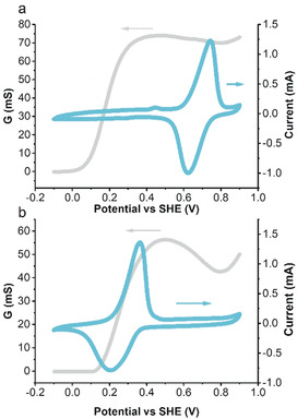
Conductance response as measured by interdigitated array electrode (grey) and cyclic voltammogram (cyan) at a scan rate of 10 mV s−1 in a 0.5 m H2SO4 electrolyte for EP(QH2)E (a) and EP(NQ)E (b).
The potential for the Q/QH2 redox reaction in pEP(QH2)E is 0.67 V vs. SHE in 0.5 m H2SO4 (aq) while the corresponding potential for NQ/NQH2 in pEP(NQ)E is 0.27 V vs. SHE. Around the NQ/NQH2 redox peak, the conductance of pEP(NQ)E reached a value of 30 mS and the Q/QH2 conversion was clearly within the high‐conductance region observed in pEP(QH2)E with an observed conductance of 65 mS. Lowering the temperature to −24 °C did not significantly affect the polymer conductance or the redox matching condition indicating that efficient electron transport provided by the polymer backbone was sustained even at sub‐zero temperatures (SI Figure S35 and S36). In addition to the achieved redox matching condition the pEP(NQ)E redox chemistry is just within the stability window of the electrolyte making the NQ group ideal for use as pendent in anode material for water‐based CRPs. In both materials the conductance provided by the polymer backbone was sufficient for efficient electron transport so that no conducting additive was needed and, when combined, they could yield a battery with a cell voltage of 0.4 V. As stated above, the CRP design rely on the pendent group to serve as capacity carrier and, from the cyclic voltammetry response we estimated the capacity contribution from the pendant redox chemistry to about 83 % and 80 % of the total capacity in pEP(QH2)E and pEP(NQ)E, respectively. The remaining capacity originates from doping of the polymer backbone and, with around 20 % of the total capacity, this suggest a doping level of half a charge per trimeric repeat unit. From the electrochemical characterization of the individual electrodes it is thus clear that both pEP(QH2)E and pEP(NQ)E meet the CRP design criteria of 1) processability, 2) redox matching, allowing for efficient electron transport, 3) pendent group dominated capacity that provides a well‐defined voltage output and 4) that the redox chemistry of both materials fall within the stability window of the electrolyte (SI section 5).
One interesting aspect of the CRP all‐organic proton battery design is that the battery can be charged not only by applying a constant current (CC), that is, galvanostatically, but also by applying a fixed potential, that is, constant voltage (CV), for a short period. Using CV as the only means of charging allows much faster charging times, and also enables direct integration with an energy‐harvesting device such as a single junction solar cell without any additional electronics for current control. In a three‐electrode setup, we applied a fixed potential, that is, we performed a potential step from ≈0.45 to 0.81 V vs. SHE, to pEP(QH2)E which oxidized (charged) QH2 to Q. This potential step drew an initial large current, starting at 45 A g−1, which rapidly faded towards 0 A g−1 and the material reached its maximum achievable capacity within 15 s (80 mAh g−1 achieved, theoretical capacity: 87 mAh g−1) (Figure 3 a black line). We maintained that potential more than five times as long (100 s) as this was the time required to fully charge the all‐organic proton battery assembled (vide infra). After 100 s the material was re‐reduced by applying a CC at 3 C, simulating a device drawing a current. Repeating 100 such charge‐discharge cycles retained 92 % of the initial capacity (Figure 3 b). Using CC galvanostatic charge‐discharge at a rate of 3 C, the initial capacity was slightly lower, around 75 mAh g−1, and the capacity during 100 cycles also faded somewhat faster (87 % retention) than with the potential step charging (Figure 3 c). Similar behaviour was observed for pEP(NQ)E but with somewhat higher stability: Potential step charging from ≈0.45 to 0.1 V vs. SHE, reducing NQ to NQH2, was complete within 45 s (Figure 3 a grey line) and achieved 68 mAh g−1 (theoretical 75 mAh g−1) upon galvanostatic discharge and the capacity was practically retained during 100 such cycles (Figure 3 b). Galvanostatic CC charging/discharging (at 3 C) gave an initial capacity of 70 mAh g−1 and 90 % capacity retention after 100 CC cycles (Figure 3 c). The specific capacities observed for pEP(QH2)E and pEP(NQ)E were comparable to those of previously reported all‐organic batteries, if conducting and binder additives are taken into consideration (SI Table S1).
Figure 3.

Individual electrode evaluation of pEP(QH2)E (black and orange) and pEP(NQ)E (grey and cyan) in 0.5 m H2SO4 (aq) using potential step charging (a) followed by galvanostatic discharge (b) as well as traditional galvanostatic charge/discharge (c). Galvanostatic charge/discharge was performed at 3 C in all cases and the potential profiles recorded during the first (pEP(QH2)E: black, pEP(NQ)E: cyan) and 100th (pEP(QH2)E: orange, pEP(NQ)E: grey) cycles are shown for both materials. Panel (a) show the current profile during the potential step charging from ≈0.5 V to 0.81 V and 0.1 V vs. SHE for pEP(QH2)E (black) and pEP(NQ)E (grey), respectively. E=3,4‐ethylenedioxythiophene; NQ=naphthoquinone; P=3,4‐propylenedioxythiophene; p=polymerized; QH2=hydroquinone.
The above characteristics are for electrodes loaded with ≈1 mg of trimer corresponding to ≈2 mg cm−2. However, for pEP(QH2)E we reached up to at least 10 mg cm−2 without any additive or binder with practically maintained specific capacity and very fast charging using the potential step method (SI Figure S38). For pEP(NQ)E, higher loadings were more challenging as the polymer did not achieve the same capacity without extensive pre‐treatment. This was probably the result of inefficient wetting of the more hydrophobic pEP(NQ)E, resulting in substantially different ion transport during doping of the polymer backbone, as suggested by EQCM data (SI Figure S40). For pEP(NQ)E, oxidation of the polymer backbone was associated with close to zero mass changes and hence the charge balance has to be attained from the combined uptake of negative ions from the electrolyte and expulsion of cations, presumably protons, already present in the polymer matrix. In clear contrast, polymer backbone oxidation for pEP(QH2)E was associated with a mass increase corresponding to a mass‐per‐mole charge of 99 g mol−1, which is close to the mass of HSO4 − (Mw=97 g mol−1). The charge balance is thus accomplished exclusively by anion uptake, indicating that charge balancing by cation expulsion is not favoured, presumably due to the possibility to accommodate volume changes associated with exclusive charge compensation by anion uptake. The extensive pre‐treatment required for pEP(NQ)E limited the characterization and battery test to ≈2 mg cm−2, which was achieved without any pre‐treatment.
Battery evaluation: We then proceeded to assemble all‐organic proton batteries in the discharged state using pEP(QH2)E and pEP(NQ)E as cathode and anode, respectively, to evaluate if similar characteristics could be achieved for battery cells. We found that the battery characteristics were well captured by the combined properties of the two individual electrode materials. That is, the average cell voltage (0.4 V) corresponded to the difference in charge/discharge plateaus between pEP(QH2)E and pEP(NQ)E and the capacity was comparable to the capacity of the limiting pEP(NQ)E electrode. When CV charging, at a voltage of 0.6 V was used the battery was fully charged within 100 s and we attribute the somewhat longer charging time to the higher pressure inside the coin cell preventing swelling of the polymer. Nonetheless, the battery was charged to 50 % within 10 s and 80 % after 25 s (Figure 4 a). The resulting discharge capacity was around 60 mAh g−1 at 3 C, which is about 80 % of the theoretical capacity of the pEP(NQ)E electrode (theoretical capacity 75 mAh g−1). The battery retained 85 % of its initial capacity after 500 cycles using CV charging followed by galvanostatic discharge (Figure 4 b). Using galvanostatic CC for both charging and discharging similarly resulted in an initial discharge capacity of 60 mAh g−1 but only about 50 % of the initial capacity was retained after 500 cycles (Figure 4 d). This shows that the initial capacity was indifferent to the charging method used and that CV charging can fully replace, and even outperform, galvanostatic charging from a stability point of view despite the high currents, which exceeded 30 A g−1.
Figure 4.
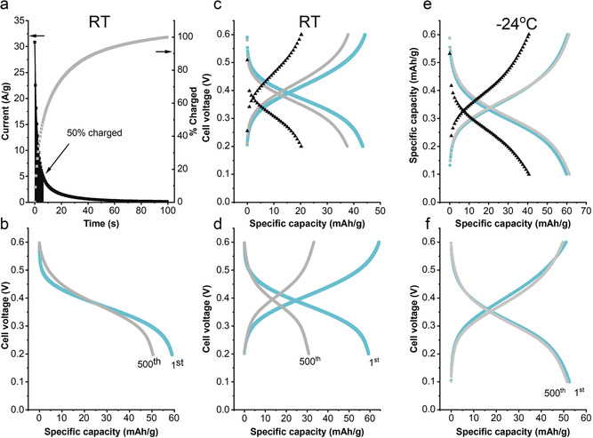
Battery evaluation at RT (a–d) and −24 °C (e,f). Current profile (a) during the constant voltage charging at RT with 50 % of charge reached after around 6.5 s (black area under graph), voltage profiles (b) for the first (cyan) and 500th (grey) cycles (85 % retention after CV charging and CC discharging at 3C). A galvanostatic C‐rate stud at RT (c) with C‐rates corresponding to 0.6 A g−1 (cyan), 1.1 A g−1 (grey) and 5.5 A g−1 (black). Voltage profile (d) for the first cycle (cyan) and 500th cycle (grey) (50 % retention after cycling at 3C, ≈95 % Coulombic efficiency). The corresponding C‐rate study (e) for a battery operating at −24 °C with C‐rates corresponding to 0.6 A g−1 (cyan), 1.1 A g−1 (grey) and 3 A g−1 (black). Voltage profile (f) for the first cycle (cyan) and 500th cycle (grey) (≈98 % retention after cycling at 3C, ≈100 % Coulombic efficiency). The capacity retention and Coulombic efficiency for all cycles can be found in Figure S42.
We rationalized the improved stability as involving detrimental side reactions that competed with the redox conversion during charging. With CV charging, most of the current was consumed by the redox conversions, which are presumed to be much faster than the side reactions. Interestingly, a traditional C‐rate study of the battery showed that galvanostatic charging of the battery was not particularly fast, compared to CV charging. This was especially clear when different CC charging currents, that is, different C‐rates, were used (Figure 4 c). At 5.5 A g−1 (100 C), only 20 mAh g−1 of the material could be accessed. At first this seems contradictory, but it effectively highlights the benefit of the CV charging method. With galvanostatic charging, the IR drop (or ohmic drop) increases linearly with charging current and is constant throughout the charging process, assuming that the resistance is independent of the state of charge. With increased current the potentials that the electrodes experience at the cut‐off voltage thus decrease and increase linearly for the positive and negative electrodes, respectively. Hence, as the charging current increases the effective voltage will decrease and, accordingly, the state of charge changes with that. With constant potential charging, the initial current is large and so is the IR drop. However, as the current rapidly decreases so does the IR drop and, at the end of the charging process, the effective voltage is likely to be quite close to the voltage applied, leading to full capacity utilization. Needless to say, the gain in capacity utilization and speed is at the expense of energy efficiency as the charging voltage exceeds the discharge voltage, and this has to be considered. Nevertheless, the feasibility of utilizing CV charging shows that the battery can withstand high charging currents without sacrificing cycling stability and is therefore practical in situations where the charging currents are variable, for example, when using photovoltaics for charging. To show this direct integration without any additional electronics, we connected the battery to a commercial organic photovoltaic cell with a rated output of 0.6 V at 6–10 mA under full sun. The battery was fully charged in 100 s by simply connecting it to the solar cell exposed to a one sun equivalent light (SI Figure S44). Next, we turned to explore the possibility of using the battery at sub‐zero temperatures for low temperature applications. In order to prevent freezing the electrolyte, that rendered the battery inactive, the sulfuric acid concentration was increased from 0.5 m to 3.3 m thus inducing a freezing point depression to −27 °C.24 With the higher electrolyte concentration galvanostatic cycling of the battery at −24 °C afforded a discharge capacity of 60 mAh g−1 up to 1.1 A g−1 and 40 mAh g−1 at 3 A g−1 (Figure 4 e). Hence, capacity and the rate capability were largely unaffected by the reduced temperature. In line with the hypothesis presented above that capacity fading is due to kinetically unfavourable side reactions, the cycling stability is improved with capacity retention of 98 % after 500 cycles and a coulombic efficiency around 100 % (Figure 4 f). For some applications an acidic liquid electrolyte is unpractical due to the risk of leakage and we therefore explored the possibility to use the CRP battery together with a polymer‐gel electrolyte. By confining the liquid electrolyte using a poly(vinyl alcohol) gel a proof‐of‐principle device was produced with close to identical cycling characteristics as the liquid electrolyte analogue (SI Figure S45). Finally, we used the batteries to power a thermometer chosen to demonstrate an application in, for example, monitoring packaging temperatures during transportation. Two batteries (containing ≈1 mg material/electrode) in series to achieve a higher voltage powered the thermometer for more than one hour, with gradually fading display intensity (SI Figure S46).
Conclusion
In this report we have presented an all‐organic CRP‐based aqueous proton battery assembled from functionalized trimeric thiophene units. The post‐deposition polymerization allows interesting possibilities with regard to processability and electrode assembly as it can be entirely solution based. Furthermore, we have shown how these materials withstand charging by applying a constant voltage, resulting in a fully charged battery within mere minutes that allows for direct integration with for example, photovoltaic devices. In addition, we show that the battery can be used down to −24 °C without significant loss in performance. As a future development both voltage (0.4 V) and capacity (60 mAh g−1) in the battery could be improved by optimization of the CRP components. In particular, quinone pendant groups providing higher potentials, for example, catechol25 or dihydroxyanthraquinones,9d would make better use of the stability window of water. The capacity could be improved by optimizing the linkage unit as well as increasing the number of redox groups per repeat unit in the polymer similar to our previous studies. Nevertheless, the present battery shows, as a proof‐of‐concept, that it is possible to construct additive‐free all‐organic aqueous batteries of the rocking‐chair type using protons as cycling ions. Aqueous proton batteries similar to that presented here would allow new exciting, safe, affordable and environmentally friendly substitutions for conventional batteries.
Conflict of interest
C.S., R.E. and Ma.Sj. have applied for a patent (1950142‐8 Sweden, Conducting redox oligomers) for the trimer molecules described herein. All other authors declare no competing financial interests.
Supporting information
As a service to our authors and readers, this journal provides supporting information supplied by the authors. Such materials are peer reviewed and may be re‐organized for online delivery, but are not copy‐edited or typeset. Technical support issues arising from supporting information (other than missing files) should be addressed to the authors.
Supplementary
Acknowledgements
This work was funded by the Swedish Energy Agency, the Carl Trygger Foundation, the Olle Engqvist Byggmästare Foundation, the ÅForsk Foundation and the Research Council Formas. We thank Dr. U. Zimmermann for help with the solar cell experiments and A. Mancebo Romero for valuable assistance with battery material preparation.
C. Strietzel, M. Sterby, H. Huang, M. Strømme, R. Emanuelsson, M. Sjödin, Angew. Chem. Int. Ed. 2020, 59, 9631.
Contributor Information
Dr. Rikard Emanuelsson, Email: Rikard.Emanuelsson@angstrom.uu.se.
Prof. Martin Sjödin, Email: Martin.Sjodin@angstrom.uu.se.
References
- 1.
- 1a. Armand M., Tarascon J. M., Nature 2008, 451, 652; [DOI] [PubMed] [Google Scholar]
- 1b. Poizot P., Dolhem F., Energy Environ. Sci. 2011, 4, 2003. [Google Scholar]
- 2. Majeau-Bettez G., Hawkins T. R., Strømman A. H., Environ. Sci. Technol. 2011, 45, 4548. [DOI] [PubMed] [Google Scholar]
- 3.
- 3a. Song Z., Zhou H., Energy Environ. Sci. 2013, 6, 2280; [Google Scholar]
- 3b. Larcher D., Tarascon J. M., Nat. Chem. 2015, 7, 19. [DOI] [PubMed] [Google Scholar]
- 4. Kim J., Kim J. H., Ariga K., Joule 2017, 1, 739. [Google Scholar]
- 5.
- 5a. Häupler B., Wild A., Schubert U. S., Adv. Energy Mater. 2015, 5, 1402034; [Google Scholar]
- 5b. Oltean V.-A., Renault S., Valvo M., Brandell D., Materials 2016, 9, 142; [DOI] [PMC free article] [PubMed] [Google Scholar]
- 5c. Schon T. B., McAllister B. T., Li P.-F., Seferos D. S., Chem. Soc. Rev. 2016, 45, 6345. [DOI] [PubMed] [Google Scholar]
- 6. Poizot P., Dolhem F., Gaubicher J., Curr. Opin. Electrochem. 2018, 9, 70. [Google Scholar]
- 7.
- 7a. Nishide H., Iwasa S., Pu Y.-J., Suga T., Nakahara K., Satoh M., Electrochim. Acta 2004, 50, 827; [Google Scholar]
- 7b. Nakahara K., Oyaizu K., Nishide H., Chem. Lett. 2011, 40, 222; [Google Scholar]
- 7c. Suga T., Ohshiro H., Sugita S., Oyaizu K., Nishide H., Adv. Mater. 2009, 21, 1627. [DOI] [PubMed] [Google Scholar]
- 8. Chen H., Armand M., Courty M., Jiang M., Grey C. P., Dolhem F., Tarascon J.-M., Poizot P., J. Am. Chem. Soc. 2009, 131, 8984. [DOI] [PubMed] [Google Scholar]
- 9.
- 9a. Sofia P., Yuman S. A. B., Chris E., Philippe M., Dominique G., Philippe P., Fabrice O., Joël G., Adv. Energy Mater. 2018, 8, 1701988; [Google Scholar]
- 9b. Perticarari S., Grange E., Doizy T., Pellegrin Y., Quarez E., Oyaizu K., Fernandez-Ropero A. J., Guyomard D., Poizot P., Odobel F., Gaubicher J., Chem. Mater. 2019, 31, 1869; [Google Scholar]
- 9c. Wild A., Strumpf M., Häupler B., Hager M. D., Schubert U. S., Adv. Energy Mater. 2016, 6, 1601415; [Google Scholar]
- 9d. Tong L., Jing Y., Gordon R. G., Aziz M. J., ACS Appl. Energy Mater. 2019, 2, 4016. [Google Scholar]
- 10. Muench S., Wild A., Friebe C., Häupler B., Janoschka T., Schubert U. S., Chem. Rev. 2016, 116, 9438. [DOI] [PubMed] [Google Scholar]
- 11.
- 11a. Yao M., Sano H., Ando H., Kiyobayashi T., Sci. Rep. 2015, 5, 10962; [DOI] [PMC free article] [PubMed] [Google Scholar]
- 11b. Emanuelsson R., Sterby M., Strømme M., Sjödin M., J. Am. Chem. Soc. 2017, 139, 4828. [DOI] [PubMed] [Google Scholar]
- 12.
- 12a. Liang Y., Jing Y., Gheytani S., Lee K.-Y., Liu P., Facchetti A., Yao Y., Nat. Mater. 2017, 16, 841; [DOI] [PubMed] [Google Scholar]
- 12b. Emanuelsson R., Karlsson C., Huang H., Kosgei C., Strømme M., Sjödin M., Russ. J. Electrochem. 2017, 53, 8; [Google Scholar]
- 12c. Moia D., Giovannitti A., Szumska A. A., Maria I. P., Rezasoltani E., Sachs M., Schnurr M., Barnes P. R. F., McCulloch I., Nelson J., Energy Environ. Sci. 2019, 12, 1349. [Google Scholar]
- 13.
- 13a. Karlsson C., Strietzel C., Huang H., Sjödin M., Jannasch P., ACS Appl. Energy Mater. 2018, 1, 6451; [Google Scholar]
- 13b. Jia X., Ge Y., Shao L., Wang C., Wallace G. G., ACS Sustainable Chem. Eng. 2019, 7, 14321. [Google Scholar]
- 14. Kim J., Lee J., You J., Park M.-S., Hossain M. S. A., Yamauchi Y., Kim J. H., Mater. Horiz. 2016, 3, 517. [Google Scholar]
- 15. Bagheri H., Ayazi Z., Naderi M., Anal. Chim. Acta 2013, 767, 1. [DOI] [PubMed] [Google Scholar]
- 16. Lefebvre M., Qi Z., Rana D., Pickup P. G., Chem. Mater. 1999, 11, 262. [Google Scholar]
- 17.
- 17a. Zotti G., Zecchin S., Schiavon G., Groenendaal L. B., Macromol. Chem. Phys. 2002, 203, 1958; [Google Scholar]
- 17b. Karlsson R. H., Herland A., Hamedi M., Wigenius J. A., Åslund A., Liu X., Fahlman M., Inganäs O., Konradsson P., Chem. Mater. 2009, 21, 1815; [Google Scholar]
- 17c. Kim B. S., Chen L., Gong J., Osada Y., Macromolecules 1999, 32, 3964. [Google Scholar]
- 18.
- 18a. Meng H., Perepichka D. F., Bendikov M., Wudl F., Pan G. Z., Yu W., Dong W., Brown S., J. Am. Chem. Soc. 2003, 125, 15151; [DOI] [PubMed] [Google Scholar]
- 18b. Meng H., Perepichka D. F., Wudl F., Angew. Chem. Int. Ed. 2003, 42, 658; [DOI] [PubMed] [Google Scholar]; Angew. Chem. 2003, 115, 682; [Google Scholar]
- 18c. Spencer H. J., Berridge R., Crouch D. J., Wright S. P., Giles M., McCulloch I., Coles S. J., Hursthouse M. B., Skabara P. J., J. Mater. Chem. 2003, 13, 2075; [Google Scholar]
- 18d. Chen S., Lu B., Duan X., Xu J., J. Polym. Sci. Part A 2012, 50, 1967. [Google Scholar]
- 19.
- 19a. Oka K., Tsujimura O., Suga T., Nishide H., Winther-Jensen B., Energy Environ. Sci. 2018, 11, 1335; [Google Scholar]
- 19b. Abdiryim T., Jamal R., Zhao C., Awut T., Nurulla I., Synth. Met. 2010, 160, 325. [Google Scholar]
- 20. Sterby M., Emanuelsson R., Huang X., Gogoll A., Strømme M., Sjödin M., Electrochim. Acta 2017, 235, 356. [Google Scholar]
- 21. Sterby M., Emanuelsson R., Mamedov F., Strømme M., Sjödin M., Electrochim. Acta 2019, 308, 277. [Google Scholar]
- 22.
- 22a. Takano T., Masunaga H., Fujiwara A., Okuzaki H., Sasaki T., Macromolecules 2012, 45, 3859; [Google Scholar]
- 22b. Ugur A., Katmis F., Li M., Wu L., Zhu Y., Varanasi K. K., Gleason K. K., Adv. Mater. 2015, 27, 4604; [DOI] [PubMed] [Google Scholar]
- 22c. Zozoulenko I., Singh A., Singh S. K., Gueskine V., Crispin X., Berggren M., ACS Appl. Polym. Mater. 2019, 1, 83. [Google Scholar]
- 23. Yang L., Huang X., Gogoll A., Strømme M., Sjödin M., J. Phys. Chem. C 2015, 119, 18956. [Google Scholar]
- 24. Reddy T. B., Linden D., Lindens Handbook of Batteries, McGraw-Hill, New York, 2010. [Google Scholar]
- 25. Chhin D., Padilla-Sampson L., Malenfant J., Rigaut V., Nazemi A., Schougaard S. B., ACS Appl. Energy Mater. 2019, 2, 7781. [Google Scholar]
Associated Data
This section collects any data citations, data availability statements, or supplementary materials included in this article.
Supplementary Materials
As a service to our authors and readers, this journal provides supporting information supplied by the authors. Such materials are peer reviewed and may be re‐organized for online delivery, but are not copy‐edited or typeset. Technical support issues arising from supporting information (other than missing files) should be addressed to the authors.
Supplementary