Abstract
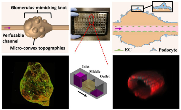
Kidney-on-a-chip devices may revolutionize the discovery of new therapies. However, fabricating a 3D glomerulus remains a challenge, due to a requirement for a microscale soft material with complex topography to support cell culture in a native configuration. Here, we describe the use of microfluidic spinning to recapitulate complex concave and convex topographies over multiple length scales, required for biofabrication of a biomimetic 3D glomerulus. We produced a microfluidic extruded topographic hollow fiber (h-FIBER), consisting of a vessel-like perfusable tubular channel for endothelial cell cultivation, and a glomerulus-like knot with microconvex topography on its surface for podocyte cultivation. Meter long h-FIBERs were produced in microfluidics within minutes, followed by chemically induced inflation for generation of topographical cues on the 3D scaffold surface. The h-FIBERs were assembled into a hot-embossed plastic 96-well plate. Long-term perfusion, podocyte barrier formation, endothelialization, and permeability tests were easily performed by a standard pipetting technique on the platform. Following long-term culture (1 month), a functional filtration barrier, measured by the transfer of albumin from the blood vessel side to the ultrafiltrate side, suggested the establishment of an engineered glomerulus.
Short abstract
A soft material with microscale topography generated in microfluidics enabled podocyte cultivation in a native glomerular configuration resulting in molecular size discrimination of barrier function.
1. Introduction
Organ-on-a-chip devices are poised to revolutionize pathophysiological studies and drug discovery. Specifically, kidney-on-a-chip devices are of particular interest, since the incidence of diabetic and hypertensive nephropathy is on the rise as the population continues to age, and nephrotoxicity is also one of the key reasons for the withdrawal of already approved drugs.1−3 The kidney is an incredibly complex organ, consisting of 26 different cell types in a precise geometrical and structural arrangement.4 It is the precise structure and orientation of these cells that are responsible for the remarkable filtration function of the kidney.
Most kidney diseases have been recognized to begin with the dysfunction of the glomerulus.5,6 The glomerulus functions as the major filtration unit of the kidney, where plasma is filtered to form concentrated urine. Considerable efforts have, therefore, been made to build an in vitro glomerulus model to better understand this filtration unit.
Developed from the self-organization of pluripotent or adult stem cells, kidney organoids have offered a notable approach for the modeling of kidney development and diseases in vitro.(7−9) While cells with the characteristics of glomerular podocytes and glomerulus-like compartments were present in these organoids, vascular flow and functional tests through the in vitro kidney organoids were never realized due to their immaturity.10,11 Though early glomerulus models, which made use of a transwell device where cells were cultured on the porous membrane, allow functional tests of cell barrier function, these static models can hardly recapitulate the flow environment of the glomerulus.12,13 Recently, advances in microfluidics have made it possible to further mimic the biomechanical microenvironment in vitro.(14,15) Flow or dynamic mechanical strain, focused on reproducing aspects of the glomerular environment, was exerted onto the glomerulus-derived cells, which have been cultured on a membrane within the microfluidic chip.16−18 The fluid was demonstrated to enhance the survival of isolated glomerular microtissues and the modeling of physio-pathological fluid environments to enable more biomimetic glomerulus models.19,20 By combining strain with physiological flow, Musah et al. demonstrated that the differentiation of human induced pluripotent stem cells into podocytes was enhanced, enabling the fabrication of a human glomerulus-on-a-chip model.21 However, even in these advanced models, cells are still cultured in a simplified 2D geometry without recapitulating the structure of a 3D glomerulus.
The kidney glomerulus is a knot of capillaries with endothelial cells (ECs) lying inside the lumen at the blood vessel side and podocytes covering the external surface at the ultrafiltrate side (Figure 1A).22,23 To enhance the function of in vitro models, appropriate structures with the intricate architecture and complexity of native organs are required.24−27 Significant efforts have been invested in the fabrication of tubular structures to mimic blood vessels by various engineering methods.28,29 It was demonstrated that 3D tubular structures could enable physiological force-driven endothelial behaviors, while a flat and stiff substrate would influence cell–cell signaling pathways related with the barrier function.30−32 However, despite the feasibility of constructing various tubular scaffolds, the absence of a microscale soft material with complex topography, to enable cell coculture in a native configuration, has limited the progress toward a biomimetic 3D glomerular structure.
Figure 1.
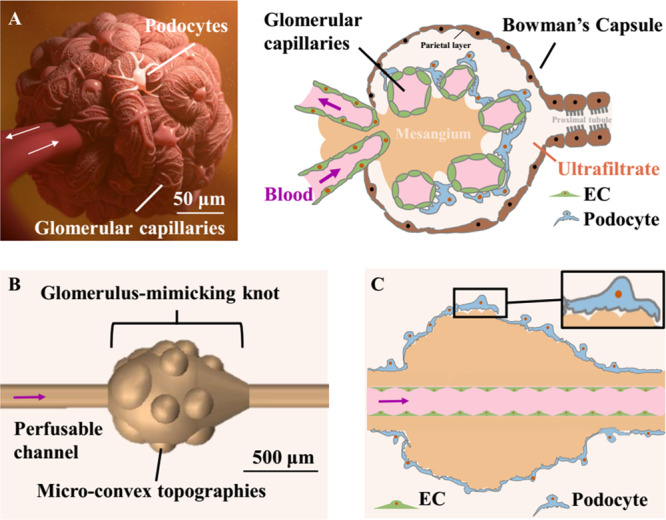
Design of the biologically inspired h-FIBER. (A) Glomerulus structure. (B) 3D structure of the h-FIBER. (C) Perfusable glomerulus model based on h-FIBER. A scale bar in part A shows the size of a typical adult kidney glomerulus.59 A scale bar in part B shows the size of a typical knot. The knot is about 3–4 times bigger than a typical glomerulus.
Here, we describe the use of microfluidic spinning to recapitulate complex concave and convex topographies over multiple length scales, required for biofabrication of a biomimetic 3D glomerulus. The technique combines high-throughput production, as meter long hollow microfibers can be generated within minutes, with chemically induced inflation of the hydrogel for instantaneous production of microscale topographical cues on the 3D microfiber surface. We term this scaffold h-FIBER, consisting of a perfusable circular channel to mimic the vascular lumen, a spindle knot to model the globular architecture of a whole glomerulus, and microconvex topography on the knot surface to recapitulate the varying patterns of capillary loops (Figure 1B,C). Different from flat 2D membranes for endothelial cell/podocyte coculture, our 3D biomimetic glomerulus is situated in a custom-made hot-embossed 96-well plate fabricated from tissue culture polystyrene to enable cell seeding, maintenance, and perfusion via gravity-driven flow, requiring no external pumps and allowing for facile liquid handling. Enhanced podocyte interdigitation was demonstrated on the knot regions of h-FIBER, compared to the tube regions. Interdigitation was further enhanced to support appropriate barrier function when these knot regions were decorated with microtopography. With the EC layer in the circular lumen, a functional glomerulus-on-a-plate platform was established, demonstrating a potential use in bioengineering and biomedical applications.
2. Results and Discussion
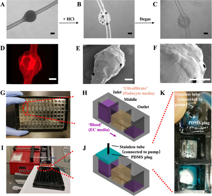
The h-FIBERs were first generated from a coaxial microfluidic device by hydrogel polymerization (Figure S1).33 Hollow microfibers with 10 knots can be fabricated within 1 min, which were then cut and used to build 10 glomerulus models in the custom designed 96-well plates. A novel chemically induced inflation method was developed to generate microconvex topography on the hydrogel surface (Figure 2A–C, Figure S2). Similar to how we blow soap bubbles by expanding air inside a soap solution, microconvex topography on the h-FIBER was created by a simple chemical reaction between CaCO3 and H+, to generate CO2 gas. These gas bubbles were trapped, expanding the hydrogel and leaving convex structures on the hydrogel surface (Figure 2D–F). The generated knot sizes were 650–950 μm (Figure S3).
Figure 2.
Fabrication of glomerulus-on-a-plate platform. (A–C) The generation of the microconvex topography on the hydrogel knot surface using chemically induced inflation method. (A) Knotted hydrogel microfiber with embedded CaCO3 beads. (D) Fluorescent image of the h-FIBER (TRITC-conjugated fluorescent beads were embedded in the hydrogel). (E) Low-magnification and (F) high-magnification SEM image showing the microconvex topography on the scaffold surface. (G) Assembly of the h-FIBERs into a 96-well plate. (H) Gravity-driven perfusion of the h-FIBER. (I) Perfusion of the h-FIBER by the syringe pump. (J) Schematics of the syringe pump connection. (K) Pump-driven flow at 70 μL/min (blue food dye indicator). Scale bars: 200 μm.
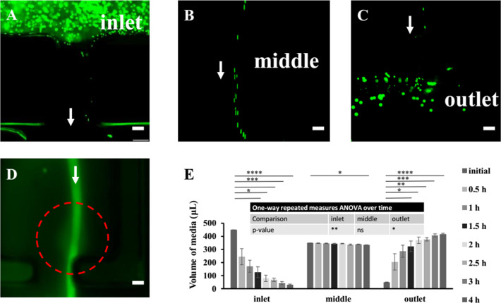
To facilitate cell attachment, RGD-conjugated alginate was used for all experiments. The diffusivity of various molecules in alginate has been reported to be high (Table S1),34−38 suggesting its feasibility for constructing a glomerulus model. By assembling and sealing the base, together with the scaffolds, onto a bottomless custom-made 96-well plate, the h-FIBERs were then fixed inside the plate with the knot in the chamber of the middle well and the two ends in the inlet and outlet wells (Figure 2G). Up to 20 h-FIBERs were assembled into one plate at the same time. Gravity-driven perfusion was realized in these scaffolds by applying the hydrostatic pressure difference between inlet and outlet (Figures 2H and 3A–C, Video S1).39−41 By connecting the plate to a syringe pump, fluid could also be pumped in the channel without leaking (Figure 2I–K). The perfusion of FITC-conjugated bovine serum albumin (FITC-BSA) solution in the lumen (Figure 3D) further demonstrated that the perfused media remained in the lumen, flowing from the inlet to the outlet (Figure 3E), while molecules (e.g., BSA) from the media could permeate the hydrogel and diffuse into the middle well. By reversibly tilting the plate every 3 h, long-term perfusion was easily realized. The calculated shear stress induced by the gravity-driven flow in the lumen ranges from 0.3 to 0.9 Pa, which is within the physiological range of blood flow-induced shear stress in a glomerulus (about 0.1–9.5 Pa).42
Figure 3.
Assembled h-FIBERS are perfusable. (A–C) Fluorescence images of the inlet, middle, and outlet wells perfused with the fluorescent beads. The arrow shows the direction of the flow. (D) Fluorescence image showing the perfusion and permeation of FITC-BSA. The arrow shows the direction of the flow. The dotted line shows the location of the glomerulus-mimicking knot. (E) Quantitative results of perfusion. The p-value of one-way repeated measures ANOVA over time for volume of media in inlet, middle, and outlet well is 0.0087 (**), 0.0694 (n.s.), and 0.0113 (*) respectively. Data are shown as average ± s.d., n = 3. * p < 0.05, ** p < 0.01, *** p < 0.001, **** p < 0.0001. Scale bars: 200 μm.
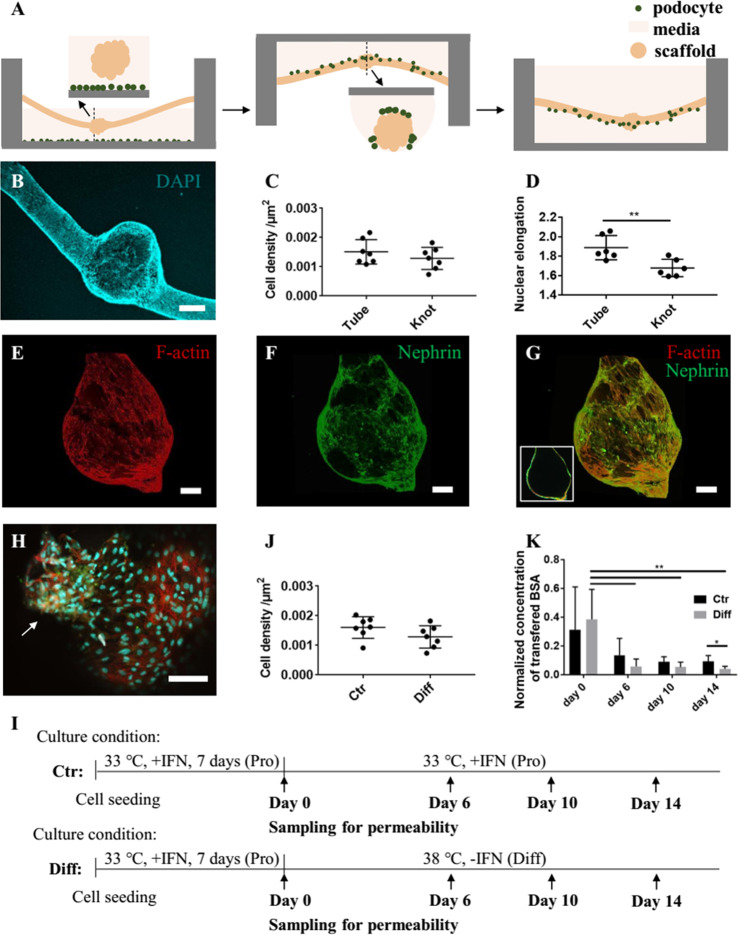
To fabricate the glomerulus model, a podocyte barrier should be established on the external surface of the glomerulus-mimicking h-FIBER. As cells tended to slip to the bottom rather than settle down on the microscaffold during seeding (Figure S4A–C), we developed a hanging-droplet cell seeding technique to improve cell attachment on the scaffold (Figure 4A, Figure S4D–F). To maintain the integrity of h-FIBERs, CaCl2 was added to the culture media in a concentration that did not affect cell viability (Figure S5). In proliferation media, the attached podocytes gradually covered the majority of the h-FIBER surface. Upon additional cultivation under differentiation conditions for 2 weeks, nuclear staining (Figure 4B) demonstrated that podocytes covered almost the entire external surface of the scaffold. The surface area of the knot is about 1 899 072 μm2, which is about 28% of the total surface area. Interestingly, though cell density on the tube and knot showed no significant difference (Figure 4C), the cell nuclei on the knot region were less elongated than on the tube region (Figure 4D).
Figure 4.
Podocytes envelop the h-FIBER forming a barrier layer. (A) Hanging-droplet cell seeding technique. (B) DAPI nuclear staining. (C) Cell density on the tube and knot. (D) Nuclear elongation on the tube and knot. (E–G) Confocal microscopy images showing the differentiated podocytes. (E) F-actin and (F) nephrin staining. (G) The merged image of F-actin and nephrin staining (the inset shows a longitudinal cross-section). (H) High-magnification image showing the merged image of F-actin, nephrin, and DAPI staining. The arrow points to the cells expressing more nephrin. (I) Timeline of cell culture for control and differentiation groups. (J) Cell density for the two groups at Day 14. (K) The transferred albumin concentration was measured at Day 0, Day 6, Day 10, and Day 14. The concentrations in the middle well were normalized to the concentration of transferred albumin measured for the cell-free h-FIBER on day 0. The p-value of one-way repeated measures ANOVA over time for the “Ctr” and “Diff” group is 0.1608 (n.s.) and 0.0015 (**), respectively. Data are shown as average ± s.d., n = 6. * p < 0.05, ** p < 0.01. Scale bar in part B is 200 μm. The other scale bars are 100 μm.
In vivo, podocyte slit diaphragms maintain glomerular filtration function. Nephrin and podocin are podocyte-specific proteins and vital components of the slit diaphragm.43,44 Nephrin and podocin expression were confirmed in the podocyte layer formed on our scaffold (Figure 4F–H, Figure S6). Probably due to the artifacts coming from the staining and imaging processes, the staining is inhomogeneous across the different knot regions. During the staining process, part of the cell layer will touch the base of the container and thus be less exposed to the antibodies. The possible inhomogeneous binding of antibodies onto the 3D cell layer might cause the inhomogeneous signal distribution. Moreover, we acquired the fluoresce image from different layers by using confocal microscopy and then did z-stacking to get the fluorescence image of the whole knot. Because the liquid and the hydrogel would cause light scattering and affect the signal, the fluorescence signals from different layers naturally vary. The above problems made it difficult to compare the intensity of the signal from the 3D cell layer. Thus, we did not use the fluorescence intensity of the immunostaining images to make a comparison for the following experiments.
Due to the perfusable bioreactor, the permeability test can be used to test the cell barrier function. The development of podocyte barrier function during differentiation (Diff) was tracked by the permeability test and compared with the nondifferentiated group (Ctr) (Figure 4I). The cell density of the two groups on day 14 showed no significant difference (Figure 4J). However, the transferred albumin decreased significantly over time for the “Diff” group but not for the “Ctr” group (Figure 4K), suggesting that podocyte differentiation was important for the development of barrier function over time.
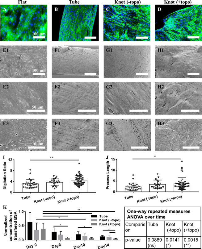
To demonstrate the effect of microtopography, we compared the arrangement of actin fibers, together with the podocyte morphology, on the normal flat PDMS surface, hydrogel tube, and the hydrogel knot with and without microtopography (Figure 5A–J). In vivo, most of the glomerular F-actin is concentrated in the foot processes, which envelop the looping capillaries and interdigitate with neighboring podocytes via slit diaphragms.45 Cytoskeletal changes in podocytes are related to foot process effacement and impaired glomerular filtration.46 More branched and interdigitated actin fibers were found on the knot with microconvex topography (Figure 5A–D). These interdigitated actin fibers are most likely used by the podocytes to remain positioned on the soft curved surface similar to the surface provided by the looping capillaries. In vivo, podocytes are exposed to tremendous physical forces, requiring concentrated F-actin to provide mechanical support and efficient attachment.47 Similar cytoskeletal structure is reported to be induced by stretch,21,48 flow stimulation,49 and topographic stimulation.27
Figure 5.
The topographical microenvironment guides podocytes’ morphology and function. Merged images of F-actin and DAPI nuclear staining (A–D) and SEM images showing the cell morphology (E–H) of podocytes, cultured on the flat PDMS (Flat), hydrogel tube (Tube), hydrogel knot without microconvex topography (Knot (-topo)), and hydrogel knot with microconvex topography (Knot (+topo)), respectively. Quantification of digitation ratio (I) and process length of podocytes (J). Digitation ratio is defined as the digitated length over the boundary length. The process length (μm) is the average length of the measured processes. The quantification method is described in Figure S7. Data were analyzed by one-way ANOVA. (K) The concentration of transferred albumin in the middle well for the hydrogel tube (Tube), hydrogel tube with knot (Knot (-topo)), and hydrogel tube with knot and microconvex topography (Knot (+topo)) with cells being differentiated for 0, 6, 10, and 14 days was tested. The concentration was normalized to the concentration of transferred albumin measured for the cell-free scaffold on day 0. The normalized concentrations of each group were analyzed by one-way repeated measures ANOVA over time. The normalized concentrations of the three groups on Day 0, Day 6, Day 10, and Day 14 were analyzed by one-way ANOVA. Data are shown as average ± s.d., * p < 0.05, ** p < 0.01.
The podocytes’ morphologies on the flat substrate, tube, and knot with/without microtopographies were also analyzed by SEM (Figure 5E–H). On the tube region, podocytes tended to elongate and align along the long axis of the tube (Figure 5F). Podocytes cultivated on the flat substrate (Figure 5E) and the knot without microtopography (Figure 5G) were more spread out compared to those on the tube but did not develop an appreciable in vivo-like arborized morphology. On the hydrogel knot with microtopography, podocytes exhibited more and longer in vivo-like branched interdigitations (Figure 5H). To confirm the morphology differences, we quantified the digitation ratio and the average process length of podocytes cultivated on the different substrates (Figure 5I,J) according to the previously published method.27 The digitation ratio and process length of podocytes on the knot with microtopography are greater than that of podocytes on the knot without microtopography and are significantly greater than that of podocytes on the tube, suggesting that the microconvex topography improves the digitation and extension of processes in podocytes. Collectively, these data indicate that the knot region with microtopography is essential for providing the in vivo-like microenvironment for podocytes.
The development of podocyte barrier function during differentiation on the tube (Tube), the knotted tube (Knot (-topo)), and the knotted tube with microtopography (Knot (+topo)) was tracked by the permeability test (Figure 5K). One-way repeated measures ANOVA showed that the transferred BSA decreased significantly over time for the “Knot (-topo)” group and the “Knot (+topo)” group, but not for the “Tube” group. Thus, the knot region is important for the development of podocyte barrier function. On day 14, the transfer of albumin from the lumen to the middle well for the “Knot (-topo)” group was significantly higher than that for the “Knot (+topo)” group, indicating that the microtopography is important for maintaining the in vivo-like cell function. Thus, the “concave and convex” geometries facilitated the formation of podocytes’ actin fibers, arborized morphology, as well as the establishment of higher barrier function.
To observe differences in transport properties as a result of molecule type, Ficoll-70 (70 kDa, ∼49.5 Å) and Ficoll-40 (40 kDa, ∼40 Å) permeability across the podocyte barrier was tested alongside both BSA and inulin (5.5 kDa). A planar transwell insert with a layer of RGD-alginate was used as a control. It was observed that cells on planar controls grew poorly, with a tendency to detach from the surface or become elongated in morphology (Figure 6A). We suspect that, in the h-FIBER configuration, the factors of curvature, microtopography, and flow all contributed to allowing cells to grow and develop with higher success rates than on planar 2D alginate surfaces. Permeability tests also demonstrated that the cells grown on planar alginate surfaces did not contribute significantly to barrier function compared to cell-free controls, and barrier function did not improve significantly with the differentiation time, as transfer levels remained nearly equivalent (1.0) when normalized to cell-free controls (Figure 6B). This is different from h-FIBER permeability results, where differentiated cells reduced transfer of BSA to below 0.2 (Figure 5K). Moreover, inulin was nearly 4 times more permeable across the h-FIBER with the podocyte layer than BSA, whereas Ficoll 49.5 Å and Ficoll 40 Å were less permeable than BSA, with Ficoll 40 Å having the most similar (∼70%) permeability values to BSA (Figure 6C). While the fixed podocyte h-FIBERs had a size-discriminating effect on the concentration of transferred molecules, the cell-free h-FIBERs did not significantly or preferentially influence the transport properties of the molecules (Figure 6C). Overall, these data confirm the contribution of 3D cell barrier function to size discrimination.
Figure 6.
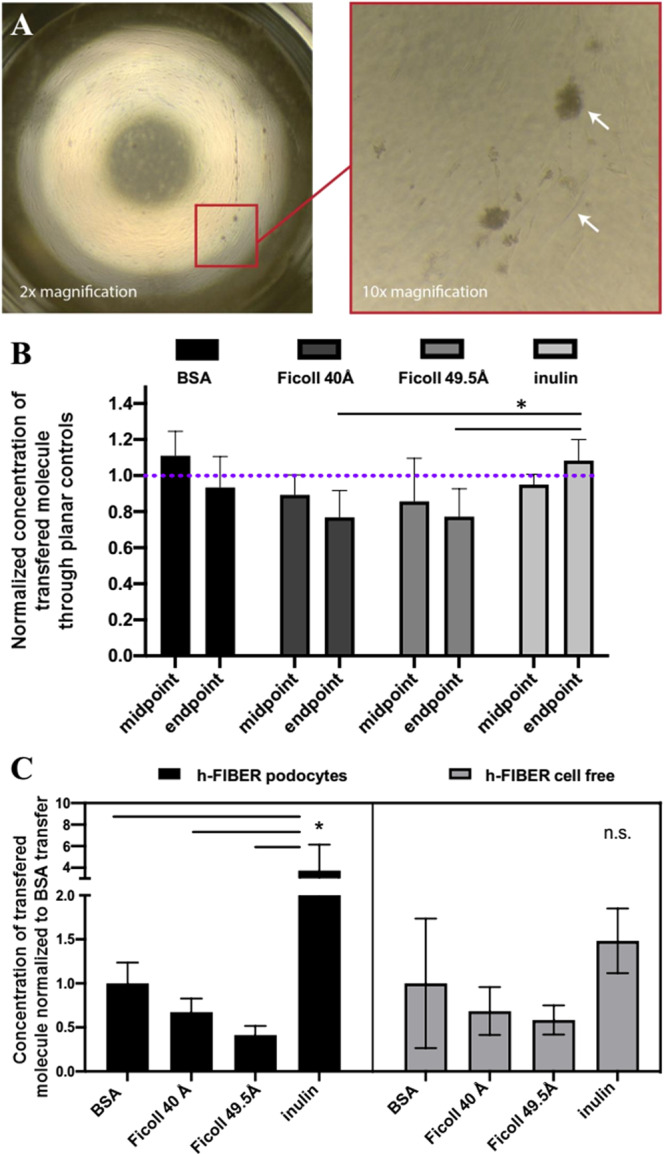
The 3D topography of h-FIBER contributes to a biomimetic size-discriminant barrier function. (A) Podocytes on planar alginate. (B) Permeability on planar controls. Permeability results for various FITC-labeled molecules across podocytes grown on planar alginate membranes, normalized to cell-free controls. Midpoint measurements were taken between days 6 and 9; endpoint measurements were taken between days 13 and 16. n = 5 samples with cells were normalized to the average of n = 4 cell-free samples. Repeated measures 2-way ANOVA confirms no significant difference over time between molecule transfer at midpoint and endpoint of differentiation time. At the endpoint, inulin had significantly more molecule transfer than Ficoll-40 (Ficoll 40 Å) and Ficoll-70 (Ficoll 49.5 Å), p < 0.05, but there was no significant difference between BSA and inulin. (C) Concentration of FITC-labeled BSA, inulin, Ficoll 40 Å, and Ficoll 49.5 Å, that was transferred across h-FIBERs with fixed podocytes or cell-free h-FIBERs, normalized to average BSA transfer, respectively. ANOVA confirms molecular-weight-dependent barrier function in configuration with fixed cells, whereas there was no significant difference in cell-free h-FIBERs. * p < 0.05.
Doxorubicin, widely used in antitumor therapy, is known to cause podocyte injury and induce proteinuria.50,51 To model the intravenous injection of doxorubicin, we added culture medium with 1 μg mL–1 doxorubicin into the inlet and outlet. BSA transferring through the drug-treated podocyte barrier increased in comparison to the control group (Figure S8), however, with milder cell barrier injury than previously reported.16,21 The slope of permeability changes over time shows a significant difference between the drug-treated group and control group (Figure S8B), suggesting that the changes might be more significant if the drug exposure time is extended. These results demonstrated the potential application of the 3D glomerulus model in building a nephropathy model in vitro. This milder cell barrier injury might be because the drug in our model was perfused in the lumen, and thus, the podocytes on the outer surface of the h-FIBER scaffold were not directly exposed to the drug in high concentration. Another possible reason is that greater maturation in 3D tissues makes it more difficult for a drug to saturate a tissue and fulfill its targeted effect and thus contributes to greater robustness and resistance to drugs, which was also demonstrated in other 3D models previously.52 The value of organ-on-a-chip systems is in reducing both false positives and false negatives in preclinical drug discovery and testing of new chemical entities. With a view of eliminating false positives, this feature may be desirable. We will explore the application of the platform in drug screening with more experiments in the future. Overall, with the current system and results, we can define specific advantages of our platform in drug testing. For example, our platform allows robust permeability tests by facile fluid sampling from the open-access wells, which will be suitable for regular workflow in the pharmaceutical industry.
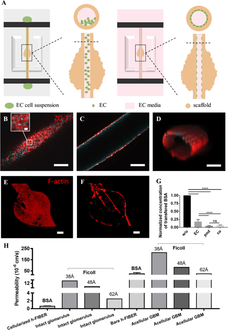
At the blood vessel side in vivo, there is a layer of ECs in the capillary lumen, which is an important component of the functional filtration barrier.23 The perfusable lumen in the h-FIBER is ideal for mimicking vascular lumen. Since the h-FIBER has been robustly assembled in the 96-well bioreactor, the seeding of ECs in the microscale hydrogel lumen was easily realized using the standard pipetting technique (Figure 7A). As the ECs proliferated and spread, a confluent EC layer covering the luminal surface was formed as confirmed with staining for ZO-1 (Figure 7B–D), a tight junction protein, as well as VE-Cadherin, an endothelial cell-specific protein (Figure S9). Compared to the cell-free h-FIBER, the permeability of the h-FIBER with ECs reduced significantly (Figure 7G), which further demonstrated the formation of a functional vascular barrier.
Figure 7.
Endothelialization and the formation of the glomerular filtration barrier. (A) Illustration of cell seeding in the lumen of h-FIBER. (B–D) Confocal microscopy images showing ZO-1 (red) and DAPI (blue) staining of EC barrier formed in the lumen. Part B shows the bottom plane with inset showing the enlarged view. Part C shows the middle plane. Part D shows the 3D view of the EC barrier. (E) Front view of the glomerular structure stained for F-actin. (F) Longitudinal cross-sectional view of the glomerular structure formed on the h-FIBER with EC layer in the lumen and podocyte layer on the external surface both stained for F-actin. (G) Normalized concentration of transferred BSA through the h-FIBERs without cells (w/o) (tested on day 0), with EC barrier (EC) (tested on day 8 after EC seeding), with podocyte barrier (pod) (tested on day 14 after podocyte differentiation), and with both EC and podocyte barrier (co) (tested on day 8 after EC seeding). (H) Comparison of the permeability of the h-FIBER and glomerulus. Though the radius of BSA is around 36 Å, the fractional clearance of albumin was reported to be similar to the fractional clearances of Ficoll with Stokes–Einstein radius of 54 Å.60 Thus, the permeability of Ficoll of similar sizes (38, 48, and 62 Å) from the intact glomerulus and acellular GBM tested in vitro were chosen as comparisons.61 Data were analyzed by one-way ANOVA and are shown as average ± s.d., **** p < 0.0001. The scale bar in the inset of part B is 20 μm. The other scale bars are 100 μm.
By culturing podocytes on the external surface and ECs on the lumen surface, a 3D glomerular filtration barrier was formed on the h-FIBER. The established glomerulus-like structure was demonstrated by F-actin staining (Figure 7E,F), demonstrating two cell layers in a precise geometrical arrangement. The permeability of the h-FIBER with both podocyte and EC layers was reduced significantly when compared to the h-FIBER with the EC layer only but did not show a significant difference when compared to the h-FIBER with the podocyte layer alone (Figure 6G). This result suggests that, in our glomerulus model, the podocyte layer contributed more to the barrier function, which is consistent with in vivo data showing that podocyte injury is a pivotal event resulting in proteinuria.53 Moreover, the permeability of the h-FIBER was estimated according to the method and the mathematical model described in the experimental section. The results are shown in Figure 7H, suggesting that the h-FIBER is slightly less permeable than acellular glomerulus basement membrane (GBM), and the cellularized h-FIBER is also slightly less permeable than the intact glomerulus. Though the physical separation of the two cell types in our model is much greater than in vivo (0.3 μm), and the cells were from nonhuman cell sources, limiting utility of this work in modeling a human system with proper cell–cell crosstalk, these results demonstrate the potential and the feasibility of this platform. In future work, we plan to use human cells (e.g., podocytes from human induced pluripotent stem cells21) and try to minimize the thickness of the alginate layer to further develop a more physiological model.
The generation of shape-controlled hydrogel scaffolds using microfluidics has drawn considerable attention for its ability to mimic different tissue constructs.54 Through precise control of fluids in the microdevices, various hollow microfibers with straight,55 folded,56 helical,57 and multiple channels58 have been mass-produced to mimic complex vascular microenvironments. However, achieving a perfusable vascular barrier within these microscaffolds was still a challenge. This limitation was rooted in the lack of a suitable bioreactor to provide reliable perfusion and the difficulty in seeding and culturing cells inside the fragile microscale hydrogel scaffolds. Here, we described a 96-well plate platform based on the h-FIBER that overcame these limitations and provided a functional glomerulus-on-a-plate.
3. Conclusions
In summary, a novel perfusable 3D engineered glomerulus based on a microfluidic extruded topographic hydrogel scaffold has been demonstrated here. The h-FIBERs were produced by microfluidic spinning technology with a chemically induced inflation method, developed to fabricate microconvex topographies on the 3D hydrogel surface for mimicking microcurved features of the looping capillaries. The assembly of the h-FIBERs into a 96-well plate allowed perfusion, cell maintenance, and a permeability test to be realized using a standard pipetting technique. Endothelial cells were seeded in the perfusable lumen to generate the vascular barrier. The podocyte layer with better barrier function was formed on capillary loop-like structures. The permeability of albumin from the vascular channel to the ultrafiltrate side was tested, demonstrating the successful fabrication of a 3D glomerulus filtration barrier. The combination of the newly developed h-FIBERs using microfluidics and coculture in a 96-well plate setting to control cell arrangement demonstrates a new approach to assemble a biomimetic glomerulus in 3D.
Acknowledgments
This work was made possible by the Natural Sciences and Engineering Research Council of Canada (NSERC) Collaborative Research and Development Grant (CRDPJ 5011), China Scholarship Council (201706210353) to R.X., NSERC Alexander Graham Bell Canada Graduate Scholarships to A.K., and the CIHR Banting Postdoctoral Fellowship to B.Z. This work was also funded by the National Natural Science Foundation of China (81872835), Ministry of Science and Technology of China (2017YFC0906902 and 2017ZX09301032), Canadian Institutes of Health Research (CIHR) Operating Grants (MOP-126027 and MOP-137107), and NSERC Discovery Grant (RGPIN 326982-10). The authors would like to thank Anrea Lam for illustration in Figure 1A.
Supporting Information Available
The Supporting Information is available free of charge at https://pubs.acs.org/doi/10.1021/acscentsci.9b01097.
Additional experimental details and figures including schematics, knot sizes, viability test results, SEM images, permeability test results, confocal microscopy images, and diffusion coefficients (PDF)
Video S1: fluorescent beads perfused through the h-FIBER lumen driven by hydrostatic pressure (MP4)
The authors declare no competing financial interest.
Supplementary Material
References
- Siramshetty V. B.; Nickel J.; Omieczynski C.; Gohlke B.; Drwal M. N.; Preissner R. WITHDRAWN—a resource for withdrawn and discontinued drugs. Nucleic Acids Res. 2016, 44, D1080–D1086. 10.1093/nar/gkv1192. [DOI] [PMC free article] [PubMed] [Google Scholar]
- Kim S. Y.; Moon A. Drug-induced nephrotoxicity and its biomarkers. Biomol. Ther. 2012, 20, 268. 10.4062/biomolther.2012.20.3.268. [DOI] [PMC free article] [PubMed] [Google Scholar]
- Shen J. X.; Youhanna S.; Zandi Shafagh R.; Kele J.; Lauschke V. M. Organotypic and microphysiological models of liver, gut, and kidney for studies of drug metabolism, pharmacokinetics, and toxicity. Chem. Res. Toxicol. 2020, 33, 38–60. 10.1021/acs.chemrestox.9b00245. [DOI] [PubMed] [Google Scholar]
- Al-Awqati Q.; Oliver J. A. Stem cells in the kidney. Kidney Int. 2002, 61, 387–395. 10.1046/j.1523-1755.2002.00164.x. [DOI] [PubMed] [Google Scholar]
- Bryer J. S.; Susztak K. Screening drugs for kidney disease: targeting the podocyte. Cell Chem. Biol. 2018, 25, 126–127. 10.1016/j.chembiol.2018.01.018. [DOI] [PubMed] [Google Scholar]
- Lih E.; Park W.; Park K. W.; Chun S. Y.; Kim H.; Joung Y. K.; Kwon T. G.; Hubbell J. A.; Han D. K. A bioinspired scaffold with anti-inflammatory magnesium hydroxide and decellularized extracellular matrix for renal tissue regeneration. ACS Cent. Sci. 2019, 5, 458–467. 10.1021/acscentsci.8b00812. [DOI] [PMC free article] [PubMed] [Google Scholar]
- Homan K. A.; Gupta N.; Kroll K. T.; Kolesky D. B.; Skylar-Scott M.; Miyoshi T.; Mau D.; Valerius M. T.; Ferrante T.; Bonventre J. V. Flow-enhanced vascularization and maturation of kidney organoids in vitro. Nat. Methods 2019, 16, 255–262. 10.1038/s41592-019-0325-y. [DOI] [PMC free article] [PubMed] [Google Scholar]
- Freedman B. S.; Brooks C. R.; Lam A. Q.; Fu H.; Morizane R.; Agrawal V.; Saad A. F.; Li M. K.; Hughes M. R.; Vander Werff R. Modelling kidney disease with CRISPR-mutant kidney organoids derived from human pluripotent epiblast spheroids. Nat. Commun. 2015, 6, 8715. 10.1038/ncomms9715. [DOI] [PMC free article] [PubMed] [Google Scholar]
- Takasato M.; Pei X. E.; Chiu H. S.; Maier B.; Baillie G. J.; Ferguson C.; Parton R. G.; Wolvetang E. J.; Roost M. S.; de Sousa Lopes S. M. C. Kidney organoids from human iPS cells contain multiple lineages and model human nephrogenesis. Nature 2015, 526, 564–568. 10.1038/nature15695. [DOI] [PubMed] [Google Scholar]
- Morizane R.; Bonventre J. V. Kidney organoids: a translational journey. Trends Mol. Med. 2017, 23, 246–263. 10.1016/j.molmed.2017.01.001. [DOI] [PMC free article] [PubMed] [Google Scholar]
- Bantounas I.; Ranjzad P.; Tengku F.; Silajdžić E.; Forster D.; Asselin M.; Lewis P.; Lennon R.; Plagge A.; Wang Q. Generation of functioning nephrons by implanting human pluripotent stem cell-derived kidney progenitors. Stem Cell Rep. 2018, 10, 766–779. 10.1016/j.stemcr.2018.01.008. [DOI] [PMC free article] [PubMed] [Google Scholar]
- Li M.; Corbelli A.; Watanabe S.; Armelloni S.; Ikehata M.; Parazzi V.; Pignatari C.; Giardino L.; Mattinzoli D.; Lazzari L.; et al. Three-dimensional podocyte–endothelial cell co-cultures: Assembly, validation, and application to drug testing and intercellular signaling studies. Eur. J. Pharm. Sci. 2016, 86, 1–12. 10.1016/j.ejps.2016.02.013. [DOI] [PubMed] [Google Scholar]
- Colombo C.; Li M.; Watanabe S.; Messa P.; Edefonti A.; Montini G.; Moscatelli D.; Rastaldi M. P.; Cellesi F. Polymer nanoparticle engineering for podocyte repair: from in vitro models to new nanotherapeutics in kidney diseases. ACS Omega 2017, 2, 599–610. 10.1021/acsomega.6b00423. [DOI] [PMC free article] [PubMed] [Google Scholar]
- Zhang B.; Korolj A.; Lai B. F. L.; Radisic M. Advances in organ-on-a-chip engineering. Nat. Rev. Mater. 2018, 3, 257–278. 10.1038/s41578-018-0034-7. [DOI] [Google Scholar]
- Wilmer M. J.; Ng C. P.; Lanz H. L.; Vulto P.; Suter-Dick L.; Masereeuw R. Kidney-on-a-Chip Technology for Drug-Induced Nephrotoxicity Screening. Trends Biotechnol. 2016, 34, 156–170. 10.1016/j.tibtech.2015.11.001. [DOI] [PubMed] [Google Scholar]
- Qu Y.; An F.; Luo Y.; Lu Y.; Liu T.; Zhao W.; Lin B. A nephron model for study of drug-induced acute kidney injury and assessment of drug-induced nephrotoxicity. Biomaterials 2018, 155, 41–53. 10.1016/j.biomaterials.2017.11.010. [DOI] [PubMed] [Google Scholar]
- Sakolish C. M.; Mahler G. J. A novel microfluidic device to model the human proximal tubule and glomerulus. RSC Adv. 2017, 7, 4216–4225. 10.1039/C6RA25641D. [DOI] [Google Scholar]
- Petrosyan A.; Cravedi P.; Villani V.; Angeletti A.; Manrique J.; Renieri A.; De Filippo R. E.; Perin L.; Da Sacco S. A glomerulus-on-a-chip to recapitulate the human glomerular filtration barrier. Nat. Commun. 2019, 10, 1–17. 10.1038/s41467-019-11577-z. [DOI] [PMC free article] [PubMed] [Google Scholar]
- Wang L.; Tao T.; Su W.; Yu H.; Yu Y.; Qin J. A disease model of diabetic nephropathy in a glomerulus-on-a-chip microdevice. Lab Chip 2017, 17, 1749–1760. 10.1039/C7LC00134G. [DOI] [PubMed] [Google Scholar]
- Zhou M.; Zhang X.; Wen X.; Wu T.; Wang W.; Yang M.; Wang J.; Fang M.; Lin B.; Lin H. Development of a functional glomerulus at the organ level on a chip to mimic hypertensive nephropathy. Sci. Rep. 2016, 6, 1–13. 10.1038/srep31771. [DOI] [PMC free article] [PubMed] [Google Scholar]
- Musah S.; Mammoto A.; Ferrante T. C.; Jeanty S. S. F.; Hirano-Kobayashi M.; Mammoto T.; Roberts K.; Chung S.; Novak R.; Ingram M.; et al. Mature induced-pluripotent-stem-cell-derived human podocytes reconstitute kidney glomerular-capillary-wall function on a chip. Nat. Biomed. Eng. 2017, 1, 1–12. 10.1038/s41551-017-0069. [DOI] [PMC free article] [PubMed] [Google Scholar]
- Du B.; Yu M.; Zheng J. Transport and interactions of nanoparticles in the kidneys. Nat. Rev. Mater. 2018, 3, 358–374. 10.1038/s41578-018-0038-3. [DOI] [Google Scholar]
- Obeidat M.; Obeidat M.; Ballermann B. J. Glomerular endothelium: A porous sieve and formidable barrier. Exp. Cell Res. 2012, 318, 964–972. 10.1016/j.yexcr.2012.02.032. [DOI] [PubMed] [Google Scholar]
- Benam K. H.; Dauth S.; Hassell B.; Herland A.; Jain A.; Jang K.; Karalis K.; Kim H. J.; MacQueen L.; Mahmoodian R. Engineered in vitro disease models. Annu. Rev. Pathol.: Mech. Dis. 2015, 10, 195–262. 10.1146/annurev-pathol-012414-040418. [DOI] [PubMed] [Google Scholar]
- Nichol J. W.; Khademhosseini A. Modular tissue engineering: engineering biological tissues from the bottom up. Soft Matter 2009, 5, 1312–1319. 10.1039/b814285h. [DOI] [PMC free article] [PubMed] [Google Scholar]
- Khademhosseini A.; Langer R. Microengineered hydrogels for tissue engineering. Biomaterials 2007, 28, 5087–5092. 10.1016/j.biomaterials.2007.07.021. [DOI] [PubMed] [Google Scholar]
- Korolj A.; Laschinger C.; James C.; Hu E.; Velikonja C.; Smith N.; Gu I.; Ahadian S.; Willette R.; Radisic M. Curvature facilitates podocyte culture in a biomimetic platform. Lab Chip 2018, 18, 3112–3128. 10.1039/C8LC00495A. [DOI] [PubMed] [Google Scholar]
- Lim K. S.; Baptista M.; Moon S.; Woodfield T. B.; Rnjak-Kovacina J. Microchannels in development, survival, and vascularisation of tissue analogues for regenerative medicine. Trends Biotechnol. 2019, 37, 1189–1201. 10.1016/j.tibtech.2019.04.004. [DOI] [PubMed] [Google Scholar]
- Xie R.; Zheng W.; Guan L.; Ai Y.; Liang Q. Engineering of hydrogel materials with perfusable microchannels for building vascularized tissues. Small 2020, 16, 1902838. 10.1002/smll.201902838. [DOI] [PubMed] [Google Scholar]
- Polacheck W. J.; Kutys M. L.; Tefft J. B.; Chen C. S. Microfabricated blood vessels for modeling the vascular transport barrier. Nat. Protoc. 2019, 14, 1425–1454. 10.1038/s41596-019-0144-8. [DOI] [PMC free article] [PubMed] [Google Scholar]
- Huber D.; Oskooei A.; Casadevall I Solvas X.; Demello A.; Kaigala G. V. Hydrodynamics in cell studies. Chem. Rev. 2018, 118, 2042–2079. 10.1021/acs.chemrev.7b00317. [DOI] [PMC free article] [PubMed] [Google Scholar]
- Kutys M. L.; Chen C. S. Forces and mechanotransduction in 3D vascular biology. Curr. Opin. Cell Biol. 2016, 42, 73–79. 10.1016/j.ceb.2016.04.011. [DOI] [PMC free article] [PubMed] [Google Scholar]
- Xie R.; Xu P.; Liu Y.; Li L.; Luo G.; Ding M.; Liang Q. Necklace-like microfibers with variable knots and perfusable channels fabricated by an oil-free microfluidic spinning process. Adv. Mater. 2018, 30, 1705082. 10.1002/adma.201705082. [DOI] [PubMed] [Google Scholar]
- Huebsch N.; Arany P. R.; Mao A. S.; Shvartsman D.; Ali O. A.; Bencherif S. A.; Rivera-Feliciano J.; Mooney D. J. Harnessing traction-mediated manipulation of the cell/matrix interface to control stem-cell fate. Nat. Mater. 2010, 9, 518–526. 10.1038/nmat2732. [DOI] [PMC free article] [PubMed] [Google Scholar]
- Chai Y.; Mei L. H.; Wu G. L.; Lin D. Q.; Yao S. J. Gelation conditions and transport properties of hollow calcium alginate capsules. Biotechnol. Bioeng. 2004, 87, 228–233. 10.1002/bit.20144. [DOI] [PubMed] [Google Scholar]
- Li R. H.; Altreuter D. H.; Gentile F. T. Transport characterization of hydrogel matrices for cell encapsulation. Biotechnol. Bioeng. 1996, 50, 365–373. . [DOI] [PubMed] [Google Scholar]
- Axelsson A.; Persson B. Determination of effective diffusion coefficients in calcium alginate gel plates with varying yeast cell content. Appl. Biochem. Biotechnol. 1988, 18, 231–250. 10.1007/BF02930828. [DOI] [Google Scholar]
- Tanaka H.; Matsumura M.; Veliky I. A. Diffusion characteristics of substrates in Ca-alginate gel beads. Biotechnol. Bioeng. 1984, 26, 53–58. 10.1002/bit.260260111. [DOI] [PubMed] [Google Scholar]
- Lai B. F. L.; Huyer L. D.; Lu R. X. Z.; Drecun S.; Radisic M.; Zhang B. InVADE: Integrated vasculature for assessing dynamic events. Adv. Funct. Mater. 2017, 27, 1703524. 10.1002/adfm.201703524. [DOI] [Google Scholar]
- Zhang B.; Montgomery M.; Chamberlain M. D.; Ogawa S.; Korolj A.; Pahnke A.; Wells L. A.; Massé S.; Kim J.; Reis L.; et al. Biodegradable scaffold with built-in vasculature for organ-on-a-chip engineering and direct surgical anastomosis. Nat. Mater. 2016, 15, 669–678. 10.1038/nmat4570. [DOI] [PMC free article] [PubMed] [Google Scholar]
- Zhang B.; Lai B. F. L.; Xie R.; Huyer L. D.; Montgomery M.; Radisic M. Microfabrication of AngioChip, a biodegradable polymer scaffold with microfluidic vasculature. Nat. Protoc. 2018, 13, 1793–1813. 10.1038/s41596-018-0015-8. [DOI] [PubMed] [Google Scholar]
- Ballermann B. J.; Dardik A.; Eng E.; Liu A. Shear stress and the endothelium. Kidney Int. 1998, 54, 100–108. 10.1046/j.1523-1755.1998.06720.x. [DOI] [PubMed] [Google Scholar]
- Ruotsalainen V.; Ljungberg P.; Wartiovaara J.; Lenkkeri U.; Kestilä M.; Jalanko H.; Holmberg C.; Tryggvason K. Nephrin is specifically located at the slit diaphragm of glomerular podocytes. Proc. Natl. Acad. Sci. U. S. A. 1999, 96, 7962–7967. 10.1073/pnas.96.14.7962. [DOI] [PMC free article] [PubMed] [Google Scholar]
- Shankland S. J.; Pippin J. W.; Reiser J.; Mundel P. Podocytes in culture: past, present, and future. Kidney Int. 2007, 72, 26–36. 10.1038/sj.ki.5002291. [DOI] [PubMed] [Google Scholar]
- Andrews P. M.; Bates S. B. Filamentous actin bundles in the kidney. Anat. Rec. 1984, 210, 1–9. 10.1002/ar.1092100102. [DOI] [PubMed] [Google Scholar]
- Perico L.; Conti S.; Benigni A.; Remuzzi G. Podocyte–actin dynamics in health and disease. Nat. Rev. Nephrol. 2016, 12, 692. 10.1038/nrneph.2016.127. [DOI] [PubMed] [Google Scholar]
- Schell C.; Huber T. B. The evolving complexity of the podocyte cytoskeleton. J. Am. Soc. Nephrol. 2017, 28, 3166–3174. 10.1681/ASN.2017020143. [DOI] [PMC free article] [PubMed] [Google Scholar]
- Endlich N.; Kress K. R.; Reiser J.; Uttenweiler D.; Kriz W.; Mundel P.; Endlich K. Podocytes respond to mechanical stress in vitro. J. Am. Soc. Nephrol. 2001, 12, 413–422. [DOI] [PubMed] [Google Scholar]
- Friedrich C.; Endlich N.; Kriz W.; Endlich K. Podocytes are sensitive to fluid shear stress in vitro. Am. J. Physiol. 2006, 291, F856–F865. 10.1152/ajprenal.00196.2005. [DOI] [PubMed] [Google Scholar]
- Zhang H.; Wang W.; Ren L.; Zhao X.; Wang Z.; Zhuang D.; Bai Y. The mTORC2/Akt/NFκB pathway-mediated activation of TRPC6 participates in adriamycin-induced podocyte apoptosis. Cell. Physiol. Biochem. 2016, 40, 1079–1093. 10.1159/000453163. [DOI] [PubMed] [Google Scholar]
- Lee J.; Kim S. Kidney-on-a-chip: a new technology for predicting drug efficacy, interactions, and drug-induced nephrotoxicity. Curr. Drug Metab. 2018, 19, 577–583. 10.2174/1389200219666180309101844. [DOI] [PubMed] [Google Scholar]
- Breslin S.; O’Driscoll L. The relevance of using 3D cell cultures, in addition to 2D monolayer cultures, when evaluating breast cancer drug sensitivity and resistance. Oncotarget 2016, 7, 45745. 10.18632/oncotarget.9935. [DOI] [PMC free article] [PubMed] [Google Scholar]
- Brinkkoetter P. T.; Ising C.; Benzing T. The role of the podocyte in albumin filtration. Nat. Rev. Nephrol. 2013, 9, 328–336. 10.1038/nrneph.2013.78. [DOI] [PubMed] [Google Scholar]
- Ma S.; Mukherjee N. Microfluidics fabrication of soft microtissues and bottom-up assembly. Adv. Biosyst. 2018, 2, 1800119. 10.1002/adbi.201800119. [DOI] [Google Scholar]
- Pi Q.; Maharjan S.; Yan X.; Liu X.; Singh B.; van Genderen A. M.; Robledo-Padilla F.; Parra-Saldivar R.; Hu N.; Jia W.; et al. Digitally tunable microfluidic bioprinting of multilayered cannular tissues. Adv. Mater. 2018, 30, 1706913. 10.1002/adma.201706913. [DOI] [PMC free article] [PubMed] [Google Scholar]
- Liu Y.; Xu P.; Liang Z.; Xie R.; Ding M.; Liu H.; Liang Q. Hydrogel microfibers with perfusable folded channels for tissue constructs with folded morphology. RSC Adv. 2018, 8, 23475–23480. 10.1039/C8RA04192J. [DOI] [PMC free article] [PubMed] [Google Scholar]
- Xu P.; Xie R.; Liu Y.; Luo G.; Ding M.; Liang Q. Bioinspired microfibers with embedded perfusable helical channels. Adv. Mater. 2017, 29, 1701664. 10.1002/adma.201701664. [DOI] [PubMed] [Google Scholar]
- Cheng Y.; Zheng F.; Lu J.; Shang L.; Xie Z.; Zhao Y.; Chen Y.; Gu Z. Bioinspired multicompartmental microfibers from microfluidics. Adv. Mater. 2014, 26, 5184–5190. 10.1002/adma.201400798. [DOI] [PubMed] [Google Scholar]
- Puelles V. G.; Douglas-Denton R. N.; Cullen-McEwen L. A.; Li J.; Hughson M. D.; Hoy W. E.; Kerr P. G.; Bertram J. F. Podocyte number in children and adults: associations with glomerular size and numbers of other glomerular resident cells. J. Am. Soc. Nephrol. 2015, 26, 2277–2288. 10.1681/ASN.2014070641. [DOI] [PMC free article] [PubMed] [Google Scholar]
- Ohlson M.; Sörensson J.; Haraldsson B. Glomerular size and charge selectivity in the rat as revealed by FITC-Ficoll and albumin. Am. J. Physiol. 2000, 279, 84–91. 10.1152/ajprenal.2000.279.1.F84. [DOI] [PubMed] [Google Scholar]
- Edwards A.; Deen W. M.; Daniels B. S. Hindered transport of macromolecules in isolated glomeruli. I. Diffusion across intact and cell-free capillaries. Biophys. J. 1997, 72, 204–213. 10.1016/S0006-3495(97)78659-4. [DOI] [PMC free article] [PubMed] [Google Scholar]
Associated Data
This section collects any data citations, data availability statements, or supplementary materials included in this article.


