Abstract
Twenty years ago, the concept of aggregation‐induced emission (AIE) was proposed, and this unique luminescent property has attracted scientific interest ever since. However, AIE denominates only the phenomenon, while the details of its underlying guiding principles remain to be elucidated. This minireview discusses the basic principles of AIE based on our previous mechanistic study of the photophysical behavior of 9,10‐bis(N,N‐dialkylamino)anthracene (BDAA) and the corresponding mechanistic analysis by quantum chemical calculations. BDAA comprises an anthracene core and small electron donors, which allows the quantum chemical aspects of AIE to be discussed. The key factor for AIE is the control over the non‐radiative decay (deactivation) pathway, which can be visualized by considering the conical intersection (CI) on a potential energy surface. Controlling the conical intersection (CI) on the potential energy surface enables the separate formation of fluorescent (CI:high) and non‐fluorescent (CI:low) molecules [control of conical intersection accessibility (CCIA)]. The novelty and originality of AIE in the field of photochemistry lies in the creation of functionality by design and in the active control over deactivation pathways. Moreover, we provide a new design strategy for AIE luminogens (AIEgens) and discuss selected examples.
Keywords: aggregation-induced emission, bis(dialkylamino)anthracene, control of conical intersection accessibility
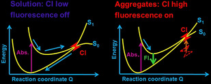
What is essential in the aggregation‐induced emission (AIE) mechanism? This question is addressed by using the photophysical processes associated with 9,10‐bis(N,N‐dialkylamino)anthracene as a case study. The AIE phenomenon requires control of the non‐radiative decay (deactivation) pathway, that is, controlling the conical intersection (CI) on the potential energy surface enables the formation of fluorescent molecules (CI high) and non‐fluorescent (CI low) molecules separately.
1. Introduction
Over the last two decades, substantial attention has focused on aggregation‐induced emission (AIE) in materials science, analytical chemistry, and life sciences.1 The unique luminescence behavior of AIE luminogens (AIEgens) has sparked the curiosity of various segments of the scientific community. After the discovery of prototypical AIEgens such as pentaphenylsilole2 and tetraphenylethene (TPE),3 research on the mechanisms of quenching in solution and emission in the solid state began (Figure 1). AIE depends first and foremost on the control over non‐radiative decay (deactivation pathways). The first proposal to control such non‐radiative decay was based on the restriction of the intramolecular rotation (RIR) model.4 In solution, non‐radiative decay of biaryl compounds occurs by axis rotation, which is restricted in the solid state. Therefore, many AIEgens exhibit multiple biaryl bonds and complex structures. The validity of the RIR model by first‐principles calculations has also been studied.5
Figure 1.

Typical AIEgens and schematic illustration of the RIR mechanism.
Recently, Tang and co‐workers proposed the restriction of intramolecular motion (RIM) model, wherein the fluorescence quenching includes contributions from both rotation (RIR) and vibration (RIV).6 Applying this strategy, they developed simple, small, and easily synthesizable AIEgens based on tetraphenylpyrazines,7 while Tanaka and co‐workers used this mechanism to design flexible organoboron or carborane complexes as AIEgens.8
However, AIE is a general term for a phenomenon, and a variety of molecular systems and emission or quenching mechanisms exist (Figure 2). AIE phenomena occur as a consequence of multiple processes such as RIR, E/Z isomerization, or the formation of J‐type aggregates.9, 10 For example, the strong emission of 1‐cyano‐trans‐1,2‐bis‐(4′‐methylbiphenyl)ethylene (CN‐MBE) in the aggregated state is largely due to the planarization of the π‐system and to the formation of J‐type aggregates.11 In the case of TPE, both RIM and planarization to expand the π‐conjugation are thought to be important factors for the observed AIE phenomena.12 Other AIEgens such as BODIPY derivatives exhibit twisted intramolecular charge transfer (TICT) in solution,1e, 13 while Schiff‐base derivatives exhibit excited state intramolecular proton transfer (ESIPT),14 and cyclooctatetrathiophene derivatives are subject to restricted skeletal isomerization.15
Figure 2.
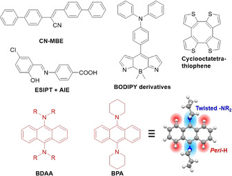
Selected representative AIEgens and a new class of AIEgens: 9,10‐Bis(N,N‐dialkylamino)anthracenes (BDAA) and their archetypical example 9,10‐bis(piperidyl)anthracene (BPA) with its crystallographic structure.
To understand the relationship between intramolecular motion and AIE properties, Blancafort and Morokuma conducted independent quantum chemical investigations16, 17, 18, 19 in order to analyze diphenyldibenzofulvene,17 tetraphenylsilole,18 and phenyleneimide19 AIEgens by restricted access to a conical intersection (RACI) model. The RACI model explains AIE in terms of the difference of non‐radiative decay rate in the different circumstances. The quantum chemical calculations predicted a largely distorted structure near the minimum energy conical intersection (MECI). In solution, the MECI is easy to access, while it becomes difficult to access in the solid state, and is prohibited in the crystalline state (Figure 3). Kokado and co‐workers applied this method to TPE and further demonstrated experimentally the importance of isomerization.20
Figure 3.
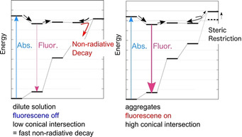
Schematic illustration of the conical intersection accessibility in dilute solution (left) and aggregates (right).
The relationship between AIEgens and photophysical processes (Jablonski diagram) is shown in Figure 4. Fluorescence quenching of AIEgens in solution must occur through an internal conversion process (S1→S0), whose efficiency is directly affected by the restrictions of intramolecular motions. Therefore, in order to rationally design AIEgens, one must design their internal conversion process so that it becomes fast only in solution but not in the solid state.
Figure 4.
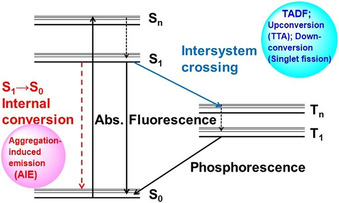
Jablonski diagram of a typical organic fluorophore.
Recently, we discovered 9,10‐bis(N,N‐dialkylamino)anthracenes (BDAA), 9,10‐bis(piperidyl)anthracene (BPA), as well as the corresponding naphthalene and pyrene analogues as a new class of AIEgens.21, 22, 23 BDAA is a unique AIEgen that neither contains isomerizable double bonds nor exhibits axial rotation and planarization of the π‐system (Figure 2). However, the excited‐state structures and luminescence properties of BDAA can be clearly explained by the RACI model. BDAA does not interact with nearby molecules in the excited state, but acts as an isolated molecule, which is advantageous for the elucidation of the AIE mechanism. Details of the features of BDAA will be described in the next chapter (vide infra).
“What is essential in the AIE mechanism?” In this minireview, we address this question and elucidate the AIE mechanism, as well as the necessary theoretical calculations and experiments in realizing the production of AIEgens based on this mechanism. In essence, we demonstrate a methodology of analyzing the photophysical properties of AIEgens to elucidate the mechanism of AIE by quantum chemical calculations, using BDAA as an example.21, 22, 23 BDAA is an ideally suited fluorescent dye to characterize AIE. Our studies revealed that it is possible to discuss photophysical processes on the basis of the potential energy surface (PES), which is similar to thermal chemical reactions, and thus to develop rational design strategies for AIEgens.22, 23 In thermal chemical reactions, transition states control the kinetics of the reaction. On the other hand, the kinetics of non‐radiative decay is mainly determined by the conical intersection (CI). Thus, the accessibility of the conical intersection determines the non‐radiative decay rates and consequently the fluorescence quantum yield. Our approach to design AIEgens is based on the concept that controlling conical intersection accessibility (CCIA) enables one to tune the fluorescence quantum yield. We also discuss the classification of previously known AIEgens and the potential of new dyes with respect to governing the fluorescence on/off mechanism by controlling the CI. Finally, the impact of AIE research on photochemistry is described.
The non‐radiative decay pathway can be explained on the PES. If a low‐lying conical intersection exists, non‐radiative decay is promoted in solution (Figure 3). This fast internal conversion leads to low fluorescence quantum yields (Φ fl) in dilute solution. In contrast, large amplitude modes such as ring puckering is prohibited in the aggregated states and internal conversion is thus not preferred; therefore, the Φ fl in the aggregated states is enhanced. In the case of BDAA, a ring puckering type CI stabilized by rotation of amino groups promotes internal conversion. The Jablonski diagram simply illustrates the interstate transition, and accordingly does not contain details about the photochemistry, given that it does not include nuclear coordinates (Figure 4).
2. Bis(N,N‐dialkylamino)anthracenes
Our quest for acene‐based AIEgens started in 2015 with the serendipitous discovery that the regioisomerism of bis(piperidyl)anthracenes (BPAs) switches their AIE/ACQ behavior.21, 24, 25 Figure 5 highlights the relationship between the photophysical properties of BPAs and their regioisomerism: the 1,4‐ (1,4‐BPA) and 9,10‐isomers (9,10‐BPA) exhibit strong AIE, whereas the other isomers show ACQ. More interesting than the regioisomeric effects were the absence of any structural features commonly observed for other reported AIEgens (vide supra). BPAs possess neither extended π‐systems with multiple free rotatable bonds, nor strong donor–acceptor pairs or isomerizable double bonds—they simply contain an anthracene ring and dialkylamino groups, whose Aryl−N bond rotation is severely hindered by peri‐hydrogen atoms. Such structurally simple and rigid D‐π‐D‐type molecules should exhibit ACQ similar to other BPA isomers. This contradictory structure–property relationship of para‐substituted BPAs motivated us to elucidate their underlying mechanism beyond the empirical discussion based on conventional organic physical chemistry.
Figure 5.
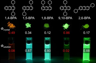
Photographs of the fluorescence of BPAs in the solid state and in solution.
Before discussing the photophysical details, several key features of 1,4‐BPA and 9,10‐BPA as AIEgens are summarized. Figure 6 illustrates the enhancement of their fluorescence intensity upon aggregation in a THF–water system. When the volume fraction of water reaches 90 vol. %, both isomers form nanoaggregates (diameter=ca. 100 nm) with high Φ fl values that are comparable to those of polycrystalline solids (Figure 5). Apart from their quantum yields, their spectral shape and position are comparable, regardless of the conditions the solids are in (e.g., nanoaggregates, millimeter‐sized crystallites, or milled dispersions in NaBr). Such robust fluorescence may be advantageous for potential imaging applications.
Figure 6.
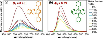
AIE behavior of a) 1,4‐BPA and b) 9,10‐BPA measured in THF–water. Fluorescence quantum yield (Φ fl) values of their aggregates (diameter: ca. 100 nm; water fraction=90 vol. %) are noted for comparison. Adapted from ref. 21 with permission from the Royal Society of Chemistry ©2015.
Another attractive feature of these BPAs is their large Stokes shifts. After the emergence of super‐resolution optical microscopy based on stimulated emission depletion (STED), numerous studies have engaged in the design of fluorescent dyes with large Stokes shifts, whereby crosstalk between the STED beam and the excitation is suppressed.26 The Stokes shifts of solid 1,4‐BPA (5500 cm−1) and 9,10‐BPA (7400 cm−1) are comparable or larger than those of the aforementioned custom‐designed dyes (Figure 7). 1,4‐BPA and 9,10‐BPA exhibit identical absorption maxima (ca. 400 nm) but fluorescence at very different spectral positions, which renders these dyes suitable candidates for potential applications in multicolor–color STED imaging using a single laser beam pair.27
Figure 7.
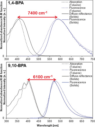
Stokes shifts of 1,4‐BPA and 9,10‐BPA in polycrystalline samples (solid lines) and in toluene solution (dashed lines). Diffuse‐reflectance spectra were measured for polycrystalline samples dispersed in NaBr. Adapted from ref. 21 with permission from the Royal Society of Chemistry ©2015.
However, the fluorescence behavior of 9,10‐BPA allows monitoring phenomena even more fundamental than aggregation. The fluorescence of the 9,10‐BPA analogue 9,10‐bis(N,N‐dimethylamino)anthracene exhibited a sensitive response to the viscosity, η, of its environment (Figure 8). Its sensitivity toward η (x=0.66) in the fluorescence intensity I(λ fl) was estimated by using the Förster–Hoffmann equation28 . As this value is comparable to that of representative molecular rotors such as 9‐(dicyanovinyl)‐julolidine (DCVJ; x=0.53)29 and Thioflavin T (x=0.72),30 we established synthetic routes to attach 9,10‐BPA derivatives with different alkyl groups (BDAAs) to other macromolecular systems.31
Figure 8.
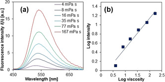
Viscosity‐sensitive fluorescence of 9,10‐bis(N,N‐dimethylamino)anthracene. a) Viscosity‐dependent fluorescence spectra and b) the corresponding double‐logarithmic plots. Adapted from ref. 22 with permission from the American Chemical Society ©2016.
Hereafter, we describe the photophysical properties common to the entire family of BDAAs, as all these exhibit outstanding AIE with comparable spectral parameters. To unlock the AIE mechanism of BDAAs one must firstly determine if the fluorescence properties of BDAAs can be discussed in the context of the RIR/RIV mechanisms,6 similar to other AIEgens. If so, Φ fl values of BDAAs should be susceptible primarily to their internal conversion efficiency.
The enhanced fluorescence of BDAAs upon aggregation can be explained by their non‐radiative transition rate. Table 1 demonstrates that aggregation largely suppresses the non‐radiative transition rate, k nr, of the 9,10‐isomer, while its radiative transition rate remained at approximately k r=5×10⁷ s−1 both in solution and in aggregates. In addition, the k nr of the 9,10‐isomer was higher in solution than those of other regioisomers, implying that 9,10‐substitution promotes fast non‐radiative transition processes that are restricted in the solid state. Although intersystem crossing is another potential non‐radiative transition besides internal conversion, we can rule out this possibility as phosphorescence was absent in BDAAs, even at 77 K. These results rationalize that AIE phenomena of BDAAs is attributed to the suppression of internal conversion in their solid states: Indeed BDAAs may serve as an ideal example to study RIR/RIV effects upon aggregation since their solid‐state fluorescence was almost free from other complicated electronic phenomena in the solid state such as J‐ or H‐ aggregate formation. Their absorption/fluorescence spectral shapes in the solid state remain unchanged from those in the solution state (Figure 7), indicating the absence of excitonic interactions. Compared to the bulky structures of typical AIEgens with efficient solid‐state fluorescence,32 the structurally compact BDAAs feature relatively small interchromophoric distances in solids (Figure S1 in the Supporting Information). Nevertheless, fluorescence of BDAAs were monomeric probably due to their large Stokes shifts with minimal structural relaxations, which can cause so‐called exciton self‐trapping, a process where local lattice deformations trap excitons into a single luminophore.33
Table 1.
Radiative (k r) and non‐radiative (k nr) transition rates of each regioisomer in solution and colloidal suspensions (THF:H2O=1:9).
|
|
THF solution |
Colloidal suspension[a] |
||
|---|---|---|---|---|
|
|
k r [106 s−1] |
k nr [106 s−1] |
k r [106 s−1] |
k nr [106 s−1] |
|
1,4‐isomer |
25 |
76 |
24 |
30 |
|
9,10‐isomer[b] |
50 |
250 |
53 |
109 |
|
1,5‐isomer |
67 |
20 |
49 |
360 |
|
1,8‐isomer |
48 |
20 |
31 |
170 |
|
2,6‐isomer |
54 |
7.2 |
43 |
250 |
[a] Rate constants were calculated based on amplitude‐averaged lifetimes. [b] The N,N‐dipropylamine analogue of 9,10‐BPA was used because the Φ fl of 9,10‐BPA (0.02) is too small to derive reliably accurate rate constants.
The discussion above clarifies that internal conversion processes play a key role in the AIE phenomena of BDAAs. Therefore, a determination of which kind of intramolecular vibrations is responsible for AIE is necessary to develop the mechanistic study into a generalized design strategy. As noted previously, BDAAs contain, unlike the majority of AIE luminogens, neither isomerizable double bonds nor extended π‐systems with multiple axial rotations. Nevertheless, in BDAAs, two Aryl–N axial rotations are present that might affect the energetics of the π‐system. Namely, if Aryl−N bond rotations would drastically diminish the S1–S0 gap, which is commonly known as the “free‐rotor effect” of the Aryl−N bonds, fast non‐radiative transitions would be promoted.34, 35 However this is not case; rotations around the Aryl−N bond hardly decreased the S1–S0 gap due to the presence of the peri‐hydrogen atoms in anthracene, which prevent the rotation. Instead, the large Stokes shifts of BDAAs arise from the “umbrella motion” of the pyramidal dialkylamino groups (Figure 9). Since such a small inversion mode can take place even in the solid state, this mode is unlikely to cause AIE. Accordingly, it seems difficult to identify large‐amplitude modes responsible for the AIE of BDAAs as long as we rely exclusively on the empirical perspective. To better understand the AIE mechanism, it is therefore necessary to undertake an ab initio approach.
Figure 9.
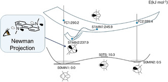
Schematic illustration of the PES of 9,10‐bis(N,N‐dimethylamino)anthracene obtained from DFT/TD‐DFT calculations at the B3LYP/6‐31+G(d) level of theory. The ground state adopts two stable conformations (S0MIN) that are interconverted through the inversion of its NR3 tetrahedra. After photoexcitation, each Franck–Condon (FC) state relaxes through planarization of one NR3, leading to the conformation shown as S1MIN1. This “umbrella motion” occurs also at the other NR3 tetrahedron under concomitant tilting of these planar trigonal planes, which gives another stable conformation (S1MIN2). These structural relaxations decrease the S0–S1 transition energy to the extent comparable with the experimental Stokes shifts. Any MECI was not sampled in this calculation and is hence not shown here.
As illustrated in Figure 3, the ab initio approach assumes that AIEgens dissipate their photoexcitation energy through CIs. If the S1/S0 CI lies sufficiently low to be accessed in solution but involves large structural deformations, such molecules are usually subject to fast internal conversion in solution but fluorescent in the solid state due to CCIA. Accordingly, the key questions for BDAAs are: 1) if they possess a suitably low‐lying S1/S0 CI for easy access, and 2) if so, how 9,10‐substitution by dialkylamino groups lowers the S1/S0 CI.
Our CASSCF(10e/8o)/6‐31G(d) calculations performed on 9,10‐bis(N,N‐dimethylamino)anthracene revealed that its S1/S0 minimum energy CI (MECI) resides at a much lower level than the excited Franck–Condon state.22 In addition, the structure at the MECI involves a large out‐of‐plane deformation of the anthracene ring with two upraised dialkylamino groups (Figure 10). Since such a large‐amplitude motion is without doubt restricted in the solid state, the AIE of 9,10‐bis(N,N‐dimethylamino)anthracene can be rationalized in terms of this bending mode on the aromatic ring.
Figure 10.
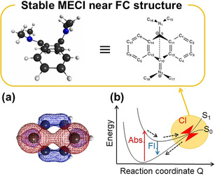
a) Natural orbital (occupation number=0.745) at the MECI calculated for benzene; b) S1/S0 MECI of 9,10‐bis(N,N‐dimethylamino)anthracene and its Lewis structure. The S0/S1 MECI search was performed at the CASSCF(10e,8o)/6‐31G(d) level of theory. Adapted from ref. 22 with permission from the American Chemical Society ©2016.
At first glance, this result seems counterintuitive to the stereotypical perception of classic polycyclic aromatic hydrocarbons (PAHs) as rigid planes. Thus, the second question must be addressed: how does the 9,10‐substitution pattern of dialkylamines “soften” the anthracene ring in the excited state? Similar ring puckering has been observed in benzene, when benzene is excited with energies higher than 0.37 eV, which triggers the specific photophysical pathway “Channel 3”.36 In Channel 3, benzenes at the S2 level are subject to fast internal conversion via the S2/S1 CI and the S1/S0 crossing seam with a Dewar‐benzene structure.37 Such a Dewar‐benzene geometry was also found in our calculations for the MECI of benzene, which displays bonding between its bridgehead positions (Figure 10). In the same way, the S1/S0 MECI of BDAA can be regarded as an analogue of Dewar benzene. Accordingly, we can expect that 9,10‐substitution in BDAAs by strong electron donors amplifies the bonding nature between the BDAA bridgehead positions, which would stabilize the Dewar‐benzene structure of the MECI. This hypothesis was confirmed by our natural orbital analysis for the S1/S0 MECI of BDAAs.22 In general, the AIE in BDAAs can be described as follows: dialkylamino groups at the 9,10‐positions stabilize the S1/S0 MECI of the anthracene ring by donating electrons to the bridge of a Dewar‐benzene‐like structure, which promotes dissipation of the photoexcitation energy via large‐amplitude bending modes.
Through these calculations and discussion, the AIE mechanism in BDAAs became clear. The next step was to generalize the insight into the design strategy of acene‐based AIE luminogens (Figure 11). In short, the design strategy consists of two simple steps. To make classic PAHs AIE‐active, firstly we must know their MECI, especially those with out‐of‐plane deformations, because their electronic states may be analogous to Dewar benzene. Fortunately, Maeda and co‐workers have already reported the MECI for benzene, naphthalene, phenanthrene, anthracene, and pyrene.38 The second step is to introduce dialkylamino groups at the positions where their aromatic rings deform the most in the MECI. During this step it will often be necessary to twist the Aryl−N bonds using steric hindrance, as twisted Aryl−N bonds can keep their Franck–Condon states and S1 minima higher than those without steric hindrance, leaving the MECI more accessible. In the following sections, we briefly exemplify this design strategy by converting the two classic aromatic hydrocarbons naphthalene22 and pyrene.23
Figure 11.
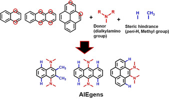
Design of dialkylamino‐substituted PAHs as new AIEgens.
According to Maeda and co‐workers,38 the most stable S1/S0 MECI of naphthalene deforms in a way that pushes its 1‐ or 4‐positions upwards. Therefore, we examined how dialkylamines at these positions would affect the photophysical properties of naphthalene in solution and in the solid state.22 When one or two dialkylamine groups were introduced in the 1,4‐position, the corresponding BDAAs exhibited moderate to strong fluorescence in solution (Figure 12). While we could not evaluate the Φ fl value of 1‐(N,N‐dimethylamino)naphthalene (DAN) crystals, 1,4‐bis(N,N‐dimethylamino)naphthalene (BDAN) exhibited enhanced fluorescence in solution (Φ fl=0.59) and in polycrystalline solids (Φ fl=0.90). As these two dyes exhibit fast internal conversions,39 this might imply that the accessibility of their S1/S0 MECI was improved simply by substitution with dialkylamine groups.
Figure 12.
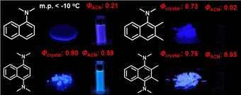
Comparison of the fluorescence quantum yields of 1‐dimethylaminonaphthalene, 1,4‐bis(dimethylamino)naphthalene, 1‐dimethylamino‐2,3‐dimethylnaphthalene, and 1,4‐bis(dimethylamino)‐2,3‐dimethyl)naphthalene together with photographic images of their fluorescence in solution or in the polycrystalline state. Adapted from ref. 22 with permission from the American Chemical Society ©2016.
This effect became much more pronounced when the dialkylamino groups were twisted via the methyl groups at the 2,3‐positions (DAN→DMe‐DAN; BDAN→DMe‐BDAN). DMe‐DAN and DMe‐BDAN exhibit faint fluorescence in solution (Φ fl=0.02–0.05), but bright solid‐state fluorescence in polycrystalline solids (Φ fl=0.73–0.78). In particular DMe‐BDAN displayed a strong viscosity effect on its fluorescence (x=0.27). Therefore, the steric hindrance around the Aryl−N bonds should be considered essential for the design of advanced AIEgens based on naphthalene.
Subsequently, we extended this design strategy to pyrene, which contains a bigger π‐system compared to the two previous examples. At the same time, pyrene serves as an important building block for larger molecular systems. According to previous reports,36 deformation around the 2‐ and 7‐positions or the K‐region (4‐, 5‐, 9‐, and 10‐positions) stabilizes the S1/S0 MECI of pyrene more than deformation at the 1‐, 3‐, 6‐, and 8‐positions.38 To test our design strategy, we synthesized the four compounds shown in Figure 13. Although the Aryl−N bonds in 4,5‐Py, 1‐Py, and 1,6‐Py are all sterically hindered both by adjacent functional groups and peri‐hydrogen atoms, only 4,5‐Py exhibits drastic AIE behavior with a prominent non‐radiative transition rate (k nr=57×107 s−1). Our calculations showed that the dilakylamino groups, which are in close proximity of each other, work cooperatively during the structural deformation, thus making the S1/S0 MECI of 4,5‐Py readily accessible. A comparison with ACQ‐active 1,6‐Py highlights the importance of these substituent positions.
Figure 13.
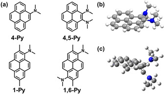
a) Molecular structure of N,N‐dimethylamine‐substituted pyrene derivatives; b) X‐ray crystallographic structure of 4,5‐Py; c) S1/S0 MECI structure calculated at the CASSCF(12e,9o)/6‐31G(d) level of theory.
3. Theoretical Insights into the AIE Mechanism
AIE can be understood as a response of the fluorescence quantum yield to the surrounding environment. An AIEgen leads to non‐radiative decay in dilute solution, but not in aggregates. In some cases, a periodic electric field in crystals can enhance the fluorescence quantum yield.40
However, AIE does not necessarily require crystallization and thus it is not feasible to consider that the enhancement of the fluorescence rate constant by the electric field from the surrounding molecules is the main reason for AIE. It seems intuitive to think that AIE is essentially due to a steric hindrance of the non‐radiative decay by surrounding molecules. Thus, once non‐radiative decay pathways on the PES are obtained, one can understand the working mechanism of the AIEgen. Non‐radiative decay pathways can be obtained in the same way as pathways for thermal chemical reactions, except that non‐radiative decay pathways contain transitions between different electronic states.
The PES is a function of the electronic energy, whose domains are nuclear coordinates. Thus, each minimum on the PES corresponds to an equilibrium structure, while each saddle point corresponds to a transition state. The minimum energy path connecting two different chemical species describes a static limit of a possible chemical reaction. Even though an actual chemical reaction at finite temperature deviates from the minimum energy path, the minimum energy path still affords a qualitative insight into the chemical reaction. Since the first successful determination of a full organometallic catalytic cycle,41 quantum chemical calculations have clarified numerous mechanisms of catalytic reactions and provided further insights to tune transition states to improve reaction rate and selectivity.
Although thermal chemical reactions can be discussed within the ground state PES, photophysical processes and photochemical reactions contain transitions between multiple PESs. After photo‐irradiation, an excited molecule is generated. Absorptions end up within negligibly short time compared to nuclear motion, and accordingly, such transitions are called vertical excitations. The excited molecule, which is in the higher singlet excited state (Sn) will rapidly relax into the lowest singlet excited state (S1) by internal conversion. The S1 state exhibits a longer lifetime than high‐lying states before the fluorescence, intersystem crossing (ISC) to the lowest triplet state (T1) state, or internal conversion to the singlet ground (S0) state. As the fluorescence occurs from the relaxed structure, the fluorescence wavelength is usually longer than the absorption wavelength. This difference is called the Stokes shift. Both ISC and internal conversion represent transitions between different states. Non‐radiative transitions between two different spin states is called ISC, while non‐radiative transitions between identical spin states are called internal conversions. Although ISCs to T1 are slower (≈ns) than internal conversions to S0 (≈ps), ISCs can be accelerated by large spin‐orbit coupling involving relatively heavy elements. Once the T1 state has been generated, it usually exhibits a very long lifetime (≈ms). Thus, bimolecular photochemical reactions in the T1 state are more likely to occur than in the S1 state. Both types of non‐radiative transition occur near the crossing seam of two PESs, and especially, a crossing seam between the same spin states is called a conical intersection (CI) (Figure 14).
Figure 14.

Schematic illustration of a typical potential energy surface (PES). Left: Low conical intersection (CI) causes competition between fluorescence and internal conversion through a CI. Middle: If a CI is sufficiently high, fluorescence becomes dominant. Right: In some cases, an ISC to the triplet state occurs, where phosphorescence ensures.
Thus, locating CIs on PESs, especially MECIs is important to understand how a molecule might engage in non‐radiative decay. Accordingly, the photostability of many types of molecules has been investigated by identifying non‐radiative decay pathways.42 Possible products after passing through CIs can be located by using the initial reaction direction (IRD) method.43 Even though the static calculation of PESs does not give any insight into the dynamics, such as the excited‐state lifetimes, it can potentially tell you which kind of distortion (or vibrational mode) is responsible for the non‐radiative decay. Just as transition states in thermal chemical reactions determine the reaction rate, tuning of the CI may determine the non‐radiative decay rate. Although some recent spectroscopic experiments have succeeded in observing CIs,44 this approach is still far from making use of CIs to design functional molecules.
AIE can be understood as a response of the fluorescence quantum yield to the surrounding environment. The fluorescence quantum yield is given as [Eq. (1)]:
| (1) |
As k r is determined by the transition dipole of the dye and thus not particularly sensitive to the surrounding environment, drastic changes of Φ fl are mainly derived from the non‐radiative decay rate k nr. If the CI is accompanied by a large distortion, stronger steric hindrance by surrounding molecules in the aggregate phase than in dilute solution can disturb the non‐radiative decay. In such cases, Φ fl is enhanced by aggregation. This is the basic idea of the CCIA strategy. Several theoretical investigations have successfully rationalized AIE in terms of the CCIA strategy.16, 22
Some experimentalists have mentioned that the possibility of E–Z isomerization of some types of AIEgens may affect the Φ fl negatively.45 The Φ fl is microscopically determined by k nr and thus fully independent from the product after internal conversion. However, the Φ fl for the entire system is determined by the mole fraction of the possible isomers. In the case that only one isomer shows AIE, the total Φ fl might actually be affected by isomerization. Nevertheless, one has to take into consideration that the E/Z isomerization itself is independent of the AIE mechanism.
4. Structure of Typical CIs and Non‐radiative Decay Pathways of AIEgens
CIs of large molecules typically results from local distortion. Thus, non‐radiative decay pathways of AIEgens can be classified according to the deformation of their building blocks. The structures of the CIs of small molecules are classified into several types, which include ring puckering, torsions of double bonds, and ring openings.46 In fact, some mechanisms of AIEgens have been reported that are based on a coordinate including double bond torsion and ring puckering. Theoretical investigations have suggested an involvement of double‐bond‐torsion‐type CIs in AIEgens such as diphenyldibenzofulvene (DPDBF),17, 47 cyano‐substituted distyrylbenzene (DBDCS),48 and 2‐(2‐hydroxyphenyl)benzothiazole (HBT).49 Ring‐puckering‐type CIs have also been found in tetraphenylsilole (DMTPS)18 and BDAA.21
Based on the CCIA strategy, we can suggest three conditions that AIEgens should satisfy: 1) The CI in solution should have low energy. This condition has to be satisfied to achieve low Φ fl in solution. Electronic control of the CI is not intuitive yet, but at least, it is possible as our BDAA succeeded in lowering the ring‐puckered CI by conjugation of the amine. 2) The CI should have a large displacement in order to acquire sensitivity to the surrounding molecular environment. 3) A small orbital overlap in aggregates to avoid ACQ. Conversely, large intermolecular orbital overlaps can lead to energy transfer pathways and negatively affect the Φ fl.
These design guidelines allow the molecular engineering of new AIEgens from small cores with known CIs. Starting from a non‐fluorescent molecule with a known CI, AIEgens can be easily obtained by introducing bulky groups at certain positions.
Ring opening/closing‐type CIs are not common in AIEgens until now. Although previous reports have suggested that the cyclization of TPE is easier than double‐bond twisting, it does not mean cyclization is the dominant mechanism of AIE in TPE (Table 2). In any case, ring opening/closing‐type CIs might be a novel candidate to achieve AIE. For example, coumarin exhibits a low‐energy CI with a ring‐opening‐type structure.50 Modifications of certain positions in order to amplify the motion toward the CI might enable the introduction of AIE behavior in coumarin derivatives. Moreover, conrotation in 4n+2 electrocyclic reactions might also be applicable, provided that energy and structure are modified suitably.
Table 2.
Classification of CIs and their corresponding compounds.
|
Structure of the CI |
Compound |
|---|---|
|
double‐bond torsion |
TPE, DPDBF, distyreneanthracene, HBDI, HBT |
|
ring puckering |
tetraphenylsilole, BDAA, cyclooctatetrathiophene |
|
ring opening/closing |
TPE |
In this section, we have discussed the relationship between structures of typical CIs of small molecules and the non‐radiative decay pathways of AIEgens. In many cases, CIs are governed by local deformation, and they thus represent good starting points to determine the mechanism of AIE in terms of possible CIs of building blocks. In fact, many known non‐radiative decay pathways of AIEgens can be classified in the same way as small molecules. Although it is still difficult to determine the structure of CIs by spectroscopy, it is already possible using computational methods. Several theoretical studies have already succeeded in explaining the basic mechanisms of AIE, and with advancing computational methods, it can be expected that it will be soon possible to predict the photophysical properties of a compound before it is synthesized.
5. Conclusions and Outlook
Aggregation‐induced emission (AIE) requires control of the non‐radiative decay, as our case study on the photophysical processes of BDAA and the mechanistic analyses by quantum chemical calculations have shown.22 Based on this concept,53 we have very recently introduced bridged stilbenes as a new type of AIE luminogens (AIEgens). The term “aggregation‐induced emission” refers to the induction of luminescence upon formation of aggregates. However, this definition does not explain the non‐radiative decay in solution. We thus propose that AIE should be explained in terms of an “environment‐responsive non‐radiative decay” concept, which regards changes of quantum yields to be derived from perturbation by surroundings.53
Theoretical investigations have revealed that it is possible to discuss photophysical processes based on a potential energy surface (PES), similar to classical chemical reactions. Controlling the conical intersection (CI) enables the separate formation of fluorescent and non‐fluorescent molecules. It should be noted that the process after passing through the CI has little effect on the AIE phenomenon itself. Although static calculations such as Fukui's intrinsic reaction coordinate (IRC) approach51 do not describe non‐adiabatic dynamics around the CI, it still provides a useful guide for possible reaction pathways. The novelty and originality of AIE is the creation of function by design and the active control of deactivation pathways (non‐radiative decay pathways) in photophysical processes (Figure 4). Although current time‐resolved absorption spectrum measurements cannot observe the behavior of AIE luminogens (AIEgens) in the excited state, it is interesting that quantum chemical calculations have already predicted transient structures during the internal conversion process. Therefore, the results of the calculations will be useful for understanding the measurement results of the chemical intermediates and transient species. In the near future, the molecular design of AIEgens using the control of conical intersection accessibility (CCIA) strategy is expected to evolve rapidly. The search for CIs by the artificial force induced reaction (AFIR) method is also possible and may be effective.52
In this minireview, we have discussed AIE in photophysical processes at single‐molecule level. On the other hand, AIEgens, which exhibit a higher quantum yield in the high order structures such as eximers and J‐aggregates, have also been reported.10, 11 In those case, we may need to include intermolecular interaction between two AIEgens. The difference between the potential energy surfaces for an AIEgen monomer and dimer would tell us what is the important reaction coordinate in such cases.
Advanced light‐emitting materials based on AIEgens and thermally activated delayed fluorescence (TADF),54 upconversion luminescent materials based on triplet–triplet annihilation (TTA)55 and singlet fission56 are not new, neither phenomenologically nor mechanistically.57 However, the design of such materials based on the fundamentals of photochemistry and state‐of‐the‐art measurements and calculations is new. Although the thus obtained results are primarily fundamental in nature, they have an immediate impact on the development of advanced light‐emitting materials. This approach is consistent with the philosophy of Confucius, who promotes “developing new ideas based on learning from the past.”58 AIE is a phenomenon that, unlike TADF and upconversion, occurs due to internal conversions, which rely on spin control (Figure 4).
AIE was reported as a curiosity 20 years ago.2 Since then, many researchers have investigated this phenomenon and numerous applications have been developed. In the near future, AIE will become an established phenomenon of functional materials that can be custom‐tailored. As said by Confucius “a visit by a friend from afar is truly a delight”,59 let us enjoy and work together in AIE research.60, 61, 62
Conflict of interest
The authors declare no conflict of interest.
Biographical Information
Satoshi Suzuki was born in Yokohama, Japan in 1985. He received his B.S., M.S. from the University of Tokyo, Department of Applied Chemistry (supervisor, Prof. Kimihiko Hirao) and his Ph.D from Kyushu University, Department of Chemistry (supervisor, Prof. Haruyuki Nakano) in 2014. Soon thereafter, he joined Prof. Morokuma's group at Fukui Institute for Fundamental Chemistry, Kyoto University, as a research fellow. His current research interests are computational photochemistry of functional materials.

Biographical Information
Shunsuke Sasaki was born in Kobe, Japan in 1992. He received his Ph.D from Tokyo Institute of Technology, Department of Chemical Science and Engineering (supervisor, Prof. Gen‐ichi Konishi) in 2017. Soon thereafter, he joined Institut des Matériaux Jean Rouxel (IMN), Université de Nantes, CNRS as a postdoctral fellow. His current research interests are topochemistry of chalcogenides, correlated electron systems and photophysics of organic dyes.

Biographical Information
Amir Sharidan Sairi was born in Selangor, Malaysia in 1994. He graduated from the Department of Polymer Chemistry, Tokyo Institute of Technology in March 2018, and is currently pursuing his Master's degree in the Department of Chemical Science and Engineering in the same university. His research includes functionalization and polymerization of AIEgens.

Biographical Information
Riki Iwai was born in Tokyo, Japan in 1997. He graduated from the Department of Polymer Chemistry, Tokyo Institute of Technology in 2019. Now, he belongs to the Department of Chemical Science and Engineering, School of Materials and Chemical Technology, Tokyo Institute of Technology. He is studying stilbenes and aggregation‐induced emission luminogens (AIEgen).

Biographical Information
Ben Zhong Tang received B.S. and Ph.D. degrees from South China University of Technology and, Department of Polymer Chemistry, Kyoto University, respectively. He conducted postdoctoral research at University of Toronto. He joined HKUST as an assistant professor in 1994 and was promoted to chair professor in 2008. He was elected to the Chinese Academy of Sciences (CAS) and the Royal Society of Chemistry(RSC) in 2009 and 2013, respectively. He is currently serving as Dean of the SCUT‐HKUST Joint Research Institute. His research interests include macromolecular chemistry, materials science, and biomedical theranostics.

Biographical Information
Gen‐ichi Konishi was born in Rochester, NY in 1971. He received his B.S., M.S. from Osaka Prefecture University, Department of Applied Chemistry (supervisor, Prof. Kazuhiko Mizuno) and his Ph.D from Kyoto University, Department of Polymer Chemistry (supervisor, Prof. Yoshiki Chujo) in 2000. He then joined Shinshu University, Division of Physiology, School of Medicine (2000) and Kanazawa University, Department of Chemistry and Chemical Engineering, (2002) as an assistant professor. In 2006, he moved to become an Associate Professor and a Principal Investigator at Tokyo Institute of Technology. His current research interests are polymer science, photochemistry, physical organic chemistry, materials chemistry, and physiology (autonomic nervous system).

Acknowledgements
We would like to thank Dr. Ulrich Mayer for proofreading this review. This work is partially supported by the Grant‐in‐Aid for Scientific Research (B) (18H02045), Innovative Areas “π‐System Figuration” (17H05145) and, JSPS Fellows (16J10324), and JSPS Overseas Research Fellowships from MEXT of Japan.
S. Suzuki, S. Sasaki, A. S. Sairi, R. Iwai, B. Z. Tang, G.-i. Konishi, Angew. Chem. Int. Ed. 2020, 59, 9856.
In Memory of Professor Dr. Keiji Morokuma
Contributor Information
Dr. Satoshi Suzuki, Email: suzuki.satoshi.8v@kyoto-u.ac.jp.
Dr. Shunsuke Sasaki, Email: shun.sasaki213@gmail.com.
Prof. Dr. Gen‐ichi Konishi, Email: konishi.g.aa@m.titech.ac.jp.
References
- 1.
- 1a. Mei J., Leung N. L. C., Kwok R. T. K., Lam J. W. Y., Tang B. Z., Chem. Rev. 2015, 115, 11718–11940; [DOI] [PubMed] [Google Scholar]
- 1b. Mei J., Hong Y., Lam J. W. Y., Qin A., Tang Y., Tang B. Z., Adv. Mater. 2014, 26, 5429–5479; [DOI] [PubMed] [Google Scholar]
- 1c. Ding D., Li K., Liu B., Tang B. Z., Acc. Chem. Res. 2013, 46, 2441–2453; [DOI] [PubMed] [Google Scholar]
- 1d. Chen Y., Lam J. W. Y., Kwok R. T. K., Liu B., Tang B. Z., Mater. Horiz. 2019, 6, 428–433; [Google Scholar]
- 1e. Sasaki S., Drummen G. P. C., Konishi G., J. Mater. Chem. C 2016, 4, 2731–2742; [Google Scholar]
- 1f. Zhao Z., Zhang H., Lam J. W. Y., Tang B. Z., Angew. Chem. Int. Ed. 2020, 10.1002/anie.201916729; [DOI] [Google Scholar]; Angew. Chem. 2020, 10.1002/ange.201916729. [DOI] [Google Scholar]
- 2.
- 2a. Luo J., Xie Z., Lam J. W. Y., Cheng L., Chen H., Qiu C., Kwok H. S., Zhan X., Liu Y., Zhuc D., Tang B. Z., Chem. Commun. 2001, 1740–1741; [DOI] [PubMed] [Google Scholar]
- 2b. Zhao Z., He B., Tang B. Z., Chem. Sci. 2015, 6, 5347–5365. [DOI] [PMC free article] [PubMed] [Google Scholar]
- 3. Tong H., Hong Y., Dong Y., Häußler M., Lam J. W. Y., Li Z., Guo Z., Tang B. Z., Chem. Commun. 2006, 1740–1741. [Google Scholar]
- 4. Chen J., Law C. C. W., Lam J. W. Y., Dong Y., Lo S. M. F., Williams I. D., Zhu D., Tang B. Z., Chem. Mater. 2003, 15, 1535–1546. [Google Scholar]
- 5. Yin S., Peng Q., Shuai Z., Fang W., Wang Y.-H., Luo Y., Phys. Rev. B 2006, 73, 205409. [Google Scholar]
- 6. Leung N. L. C., Xie N., Yuan W. Z., Liu Y., Wu Q., Peng Q., Miao Q., Lam J. W. Y., Tang B. Z., Chem. Eur. J. 2014, 20, 15349–15353. [DOI] [PubMed] [Google Scholar]
- 7. Chen M., Li L., Nie H., Tong J., Yan L., Xu B., Sun J. Z., Tian W., Zhao Z., Qin A., Tang B. Z., Chem. Sci. 2015, 6, 1932–1937. [DOI] [PMC free article] [PubMed] [Google Scholar]
- 8.
- 8a. Tanaka K., Nishino K., Ito S., Yamane H., Suenaga K., Hashimoto K., Chujo Y., Faraday Discuss. 2017, 196, 31–42; [DOI] [PubMed] [Google Scholar]
- 8b. Yoshii R., Hirose A., Tanaka K., Chujo Y., Chem. Eur. J. 2014, 20, 8320–8324. [DOI] [PubMed] [Google Scholar]
- 9. Zhang G. F., Chen Z. Q., Aldred M. P., Hu Z., Chen T., Huang Z., Meng X., Zhu M. Q., Chem. Commun. 2014, 50, 12058–12060. [DOI] [PubMed] [Google Scholar]
- 10. Tseng N. W., Liu J., Ng J. C. Y., Lam J. W. Y., Sung H. H. Y., Williams I. D., Tang B. Z., Chem. Sci. 2012, 3, 493–497. [Google Scholar]
- 11. An B. K., Kwon S. K., Jung S. D., Park S. Y., J. Am. Chem. Soc. 2002, 124, 14410–14415. [DOI] [PubMed] [Google Scholar]
- 12.
- 12a. Feng H. T., Yuan Y. X., Xiong J. B., Zheng Y. S., Tang B. Z., Chem. Soc. Rev. 2018, 47, 7452–7476; [DOI] [PubMed] [Google Scholar]
- 12b. Xiong J. B., Feng H. T., Sun J. P., Xie W. Z., Yang D., Liu M., Zheng Y. S., J. Am. Chem. Soc. 2016, 138, 11469–11472. [DOI] [PubMed] [Google Scholar]
- 13. Hu R., Lager E., Aguilar-Aguilar A., Liu J., Lam J. W. Y., Sung H. H. Y., Williams I. D., Zhong Y., Wong K. S., Peña-Cabrera E., Tang B. Z., J. Phys. Chem. C 2009, 113, 15845–15853. [Google Scholar]
- 14. Song P., Chen X., Xiang Y., Huang L., Zhou Z., Wei R., Tong A., J. Mater. Chem. 2011, 21, 13470–13475. [Google Scholar]
- 15. Zhao Z., Zheng X. Y., Du L. L., Xiong Y., He W., Gao X. X., Li C. L., Liu Y. J., Xu B., Zhang J., Song F. Y., Yu Y., Zhao X. Q., Cai Y. J., He X. W., Kwok R. T. K., Lam J. W. Y., Huang X. H., Phillips D. L., Wang H., Tang B. Z., Nat. Commun. 2019, 10, 2952. [DOI] [PMC free article] [PubMed] [Google Scholar]
- 16. Crespo-Otero R., Li Q., Blancafort L., Chem. Asian J. 2019, 14, 700–714. [DOI] [PubMed] [Google Scholar]
- 17. Li Q., Blancafort L., Chem. Commun. 2013, 49, 5966–5968. [DOI] [PubMed] [Google Scholar]
- 18. Peng X. L., Ruiz-Barragan S., Li Z. S., Li Q. S., Blancafort L., J. Mater. Chem. C 2016, 4, 2802–2810. [Google Scholar]
- 19. Suzuki S., Maeda S., Morokuma K., J. Phys. Chem. A 2015, 119, 11479–11487. [DOI] [PubMed] [Google Scholar]
- 20.
- 20a. Kokado K., Machida T., Iwasa T., Taketsugu T., Sada K., J. Phys. Chem. C 2018, 122, 245–251; [Google Scholar]
- 20b. Kokado K., Sada K., Angew. Chem. Int. Ed. 2019, 58, 8632–8639; [DOI] [PubMed] [Google Scholar]; Angew. Chem. 2019, 131, 8724–8731. [Google Scholar]
- 21. Sasaki S., Igawa K., Konishi G., J. Mater. Chem. C 2015, 3, 5940–5950. [Google Scholar]
- 22. Sasaki S., Suzuki S., Sameera W. M. C., Igawa K., Morokuma K., Konishi G., J. Am. Chem. Soc. 2016, 138, 8194–8206. [DOI] [PubMed] [Google Scholar]
- 23. Sasaki S., Suzuki S., Igawa K., Konishi G., J. Org. Chem. 2017, 82, 6865–6873. [DOI] [PubMed] [Google Scholar]
- 24.We reported a type of push–pull fluorescent solvatochromic dyes. In the synthesis step of the anthracene analog, 9,10-BPA was obtained as a by-product. We purified the crude sample by silica gel column chromatography. The obtained by-product solution did not exhibit fluorescence. After solvent evaporation, the obtained solid showed strong green fluorescence under 365 nm UV light.
- 24a. Sasaki S., Niko Y., Klymchenko A. S., Konishi G., Tetrahedron 2014, 70, 7551–7559; [Google Scholar]
- 24b. Sasaki S., Niko Y., Igawa K., Konishi G., RSC Adv. 2014, 4, 33474–33477; [Google Scholar]
- 24c. Niko Y., Kawauchi S., Konishi G., Chem. Eur. J. 2013, 19, 9760–9765; [DOI] [PubMed] [Google Scholar]
- 24d. Niko Y., Didier P., Mely I., Konishi G., Klymchenko A. S., Sci. Rep. 2016, 6, 18870. [DOI] [PMC free article] [PubMed] [Google Scholar]
- 25.We also studied the conjugation between highly twisted amino groups and π-systems. 9,10-Bis(diphenylamino)anthracene is a host molecule in OLEDs. We clarified the origin of its photophysical properties: Sasaki S., Hattori K., Igawa K., Konishi G., J. Phys. Chem. A 2015, 119, 4898–4906. [DOI] [PubMed] [Google Scholar]
- 26.
- 26a. Sednev M. V., Belov V. N., Hell S. W., Methods Appl. Fluoresc. 2015, 3, 042004; [DOI] [PubMed] [Google Scholar]
- 26b. Gandioso A., Bresolí-Obach R., Nin-Hill A., Bosch M., Palau M., Galindo A., Contreras S., Rovira A., Rovira C., Nonell S., Marchán V., J. Org. Chem. 2018, 83, 1185–1195; [DOI] [PubMed] [Google Scholar]
- 26c. Schlüter F., Riehemann K., Kehr N. S., Quici S., Daniliuc C. G., Rizzo F., Chem. Commun. 2018, 54, 642–645. [DOI] [PubMed] [Google Scholar]
- 27.
- 27a. Tønnesen J., Nadrigny F., Willig K. I., Wedlich-Söldner R., Nägerl U. V., Biophys. J. 2011, 101, 2545–2552; [DOI] [PMC free article] [PubMed] [Google Scholar]
- 27b. Bottanelli F., Kromann E. B., Allgeyer E. S., Erdmann R. S., Baguley S. W., Sirinakis G., Schepartz A., Baddeley D., Toomre D. K., Rothman J. E., Bewersdorf J., Nat. Commun. 2016, 7, 10778. [DOI] [PMC free article] [PubMed] [Google Scholar]
- 28. Förster T., Hoffmann G., Z. Phys. Chem. (Muenchen Ger.) 1971, 75, 63–76. [Google Scholar]
- 29. Haidekker M. A., Brady T. P., Lichlyter D., Theodorakis E. A., Bioorg. Chem. 2005, 33, 415–425. [DOI] [PubMed] [Google Scholar]
- 30. Chatterjee A., Seth D., Photochem. Photobiol. Sci. 2013, 12, 369–383. [DOI] [PubMed] [Google Scholar]
- 31.
- 31a. Sasaki S., Konishi G., RSC Adv. 2017, 7, 17403–17416; [Google Scholar]
- 31b. Sasaki S., Sugita Y., Tokita M., Suenobu T., Ishitani O., Konishi G., Macromolecules 2017, 50, 3544–3556; [Google Scholar]
- 31c. Sairi A. S., Konishi G., Asian J. Org. Chem. 2019, 8, 404–410; [Google Scholar]
- 31d. Sairi A. S., Kuwahara K., Sasaki S., Suzuki S., Igawa K., Tokita M., Ando S., Morokuma K., Suenobu T., Konishi G., RSC Adv. 2019, 9, 21733–21740. [DOI] [PMC free article] [PubMed] [Google Scholar]
- 32. Zeng Q., Li Z., Dong Y., Di C., Qin A., Hong Y., Ji L., Zhu Z., Jim C. K. W., Yu G., Li Q., Li Z., Liu Y., Qin J., Tang B. Z., Chem. Commun. 2007, 70–72. [DOI] [PubMed] [Google Scholar]
- 33. Toyozawa Y., J. Phys. Soc. Jpn. 1989, 58, 2626–2629. [Google Scholar]
- 34. Turro N. J., Ramamurthy V., Scaiano J. C., Principles of Molecular Photochemistry: An Introduction, University Science Books, Sausalito, 2009, pp. 288. [Google Scholar]
- 35.
- 35a. Calzaferri G., Gugger H., Leutwyler S., Helvetica Chim. Acta 1976, 59, 1969–1987; [Google Scholar]
- 35b. Lin S. H., J. Chem. Phys. 1973, 58, 5760. [Google Scholar]
- 36.
- 36a. Parker D. S. N., Minns R. S., Penfold T. J., Worth G. A., Fielding H. H., Chem. Phys. Lett. 2009, 469, 43–47; [Google Scholar]
- 36b. Féraud G., Pino T., Falvo C., Parneix P., Combriat T., Bréchignac Ph., J. Phys. Chem. Lett. 2014, 5, 1083–1090. [DOI] [PubMed] [Google Scholar]
- 37. Palmer I. J., Ragazos N., Bernardi F., Olivucci M., Robb M. A., J. Am. Chem. Soc. 1993, 115, 673–682. [Google Scholar]
- 38. Harabuchi Y., Taketsugu T., Maeda S., Phys. Chem. Chem. Phys. 2015, 17, 22561–22565. [DOI] [PubMed] [Google Scholar]
- 39.
- 39a. Takehira K., Suzuki K., Hiratsuka H., Tobita S., Chem. Phys. Lett. 2005, 413, 52–58; [Google Scholar]
- 39b. Suna X., Wenb Z. C., Jiang Y. B., Spectrochim. Acta Part A 2007, 68, 220–224. [DOI] [PubMed] [Google Scholar]
- 40.
- 40a. Presti D., Wilbraham L., Targa C., Labat F., Pedone A., Menziani M. C., Ciofini I., Adamo C., J. Phys. Chem. C 2017, 121, 5747–5752; [Google Scholar]
- 40b. Yuan M. S., Wang D. E., Xue P., Wang W., Wang J. C., Tu Q., Liu Z., Liu Y., Zhang Y., Wang J., Chem. Mater. 2014, 26, 2467–2477. [Google Scholar]
- 41.
- 41a. Koga N., Daniel C., Han J., Fu X. Y., Morokuma K., J. Am. Chem. Soc. 1987, 109, 3455–3456; [Google Scholar]
- 41b. Koga N., Morokuma K., ACS Symp. Ser. 1989, 394, 77–91; [Google Scholar]
- 41c. Daniel C., Koga N., Han J., Fu X. Y., Morokuma K., J. Am. Chem. Soc. 1988, 110, 3773–3787. [Google Scholar]
- 42.
- 42a. Sobolewskia A. L., Domckeb W., Chem. Phys. 2000, 259, 181–191; [Google Scholar]
- 42b. Domcke W., Yarkony D. R., Annual Rev. Phys. Chem. 2012, 63, 325–352; [DOI] [PubMed] [Google Scholar]
- 42c. Marchetti B., Karsili T. N. V., Ashfold M. N. R., Domckeb W., Phys. Chem. Chem. Phys. 2016, 18, 20007–20027; [DOI] [PubMed] [Google Scholar]
- 42d. Curchod B. F. E., Martínez T. J., Chem. Rev. 2018, 118, 3305–3336. [DOI] [PubMed] [Google Scholar]
- 43.
- 43a. Garavelli M., Theor. Chem. Acc. 2006, 116, 87–105; [Google Scholar]
- 43b. Garavelli M., Celani P., Fato M., Bearpark M. J., Smith B. R., J. Phys. Chem. A 1997, 101, 2023–2032; [Google Scholar]
- 43c. Celani P., Robb M. A., Garavelli M., Bernardi F., Olivucci M., Chem. Phys. Lett. 1995, 243, 1–8. [Google Scholar]
- 44.
- 44a. Yang J., Zhu X., Wolf T. J. A., Li Z., Nunes J. P. F., Coffee R., Cryan J. P., Gühr M., Hegazy K., Heinz T. F., Jobe K., Li R., Shen X., Veccione T., Weathersby S., Wilkin K. J., Yoneda C., Zheng Q., Martinez T. J., Centurion M., Wang X., Science 2018, 361, 64–67; [DOI] [PubMed] [Google Scholar]
- 44b. Neville S. P., Chergui M., Stolow Al., Schuurman M. S., Phys. Rev. Lett. 2018, 120, 243001. [DOI] [PubMed] [Google Scholar]
- 45. Yang Z., Qin W., Leung N. L. C., Arseneault M., Lam J. W. Y., Liang G., Sung H. H. Y., Williams I. D., Tang B. Z., J. Mater. Chem. C 2016, 4, 99–107. [Google Scholar]
- 46. Nakai H., Inamori M., Ikabata Y., Wang Q., J. Phys. Chem. A 2018, 122, 8905–8910. [DOI] [PubMed] [Google Scholar]
- 47. Tong H., Dong Y., Hong Y., Häussler M., Lam J. W. Y., Sung H. H. Y., Yu X., Sun J., Williams I. D., Kwok H. S., Tang B. Z., J. Phys. Chem. C 2007, 111, 2287–2294. [Google Scholar]
- 48. Shi J., Suarez L. E. A., Yoon S. J., Varghese S., Serpa C., Park S. Y., Orcid L. L., Roca-Sanjuán D., Milián-Medina B., Gierschner J., J. Phys. Chem. C 2017, 121, 23166–23183. [Google Scholar]
- 49. Zhang W., Suzuki S., Cho S. Y., Watanabe G., Yoshida H., Sakurai T., Aotani M., Tsutsui Y., Ozaki M., Seki S., Langmuir 2019, 35, 14031–14041. [DOI] [PubMed] [Google Scholar]
- 50.
- 50a. Krauter C. M., Möhring J., Buckup T., Pernpointner M., Motzkusb M., Phys. Chem. Chem. Phys. 2013, 15, 17846–17861; [DOI] [PubMed] [Google Scholar]
- 50b. Murdock D., Ingle R. A., Sazanovich I. V., Clark I. P., Harabuchi Y., Taketsugu T., Maeda S., Orr-Ewinga A. J., Ashfold M. N. R., Phys. Chem. Chem. Phys. 2016, 18, 2629–2638. [DOI] [PubMed] [Google Scholar]
- 51. Fukui K., Acc. Chem. Res. 1981, 14, 363–368. [Google Scholar]
- 52. Maeda S., Ohno K., Morokuma K., Phys. Chem. Chem. Phys. 2013, 15, 3683–3701. [DOI] [PubMed] [Google Scholar]
- 53. Iwai R., Suzuki S., Sasaki S., Sairi A. S., Igawa K., Suenobu T., Morokuma K., Konishi G., Angew. Chem. Int. Ed. 2020, 10.1002/anie.202000943; [DOI] [PubMed] [Google Scholar]; Angew. Chem. 2020, 10.1002/ange.202000943. [DOI] [Google Scholar]
- 54.
- 54a. Uoyama H., Goushi K., Shizu K., Nomura H., Adachi C., Nature 2012, 492, 234; [DOI] [PubMed] [Google Scholar]
- 54b. Adachi C., Jpn. J. Appl. Phys. 2014, 53, 060101. [Google Scholar]
- 55. Zhou J., Liu Q., Feng W., Sun Y., Li F. Y., Chem. Rev. 2015, 115, 395–465. [DOI] [PubMed] [Google Scholar]
- 56. Smith M. B., Michl J., Chem. Rev. 2010, 110, 6891–6936. [DOI] [PubMed] [Google Scholar]
- 57.Stokes reported an “AIE” effect in an inorganic salt system in 1853!: Stokes G. G., Philos. Trans. R. Soc. London 1853, 143, 385–396. [Google Scholar]
- 58.in Chinese “子曰, 温故而知新, 可以為師矣” in Japanese “温故知新(onko-chishin)” by Confucius “孔子” (Chinese philosopher, 551-479 BC).
- 59.in Chinese “有朋自遠方来, 不亦楽乎” in Japanese “朋有り遠方より来る, また楽しからずや”.
- 60.AIE research articles selected for a tutorial at the MRS Fall Meeting 2019:
- 60a. Feng G., Liu B., Acc. Chem. Res. 2018, 51, 1404–1414; [DOI] [PubMed] [Google Scholar]
- 60b. Hu F., Xu S., Liu B., Adv. Mater. 2018, 30, 1801350; [DOI] [PubMed] [Google Scholar]
- 60c. Iasilli G., Battisti A., Tantussi F., Fuso F., Allegrini M., Ruggeri G., Pucci A., Macromol. Chem. Phys. 2014, 215, 499–506; [Google Scholar]
- 60d. Ou D., Yu T., Yang Z., Luan T., Mao Z., Zhang Y., Liu S., Xu J., Chi Z., Bryce M. R., Chem. Sci. 2016, 7, 5302–5306; [DOI] [PMC free article] [PubMed] [Google Scholar]
- 60e. Yang L., Ye P., Li W., Zhang W., Guan Q., Ye C., Dong T., Wu X., Weijun Z., Gu X., Peng Q., Tang B. Z., Huang H., Adv. Opt. Mater. 2018, 6, 1701394; see also ref. [12b]. [Google Scholar]
- 61.See also articles in the Special Collection of Angewandte Chemie for the 20th anniversary of AIE:
- 61a. Xu L., Xu L., Wang Z., Wang R., Wang L., He X., Jiang H., Tang H., Cao D., Tang B. Z., Angew. Chem. Int. Ed. 2020, 10.1002/anie.201907678; [DOI] [Google Scholar]; Angew. Chem. 2020, 10.1002/ange.201907678; [DOI] [Google Scholar]
- 61b. Wang C., Qiao Q., Chi W., Chen J., Liu W., Tan D., McKechnie S., Lyu D., Jiang X. F., Zhou W., Xu N., Zhang Q., Xu Z., Liu X., Angew. Chem. Int. Ed. 2020, 10.1002/anie.201916357; [DOI] [PubMed] [Google Scholar]; Angew. Chem. 2020, 10.1002/ange.201916357; [DOI] [Google Scholar]
- 61c. Wang G., Zhou L., Zhang P., Zhao E., Zhou L., Chen D., Sun J., Gu X., Yang W., Tang B. Z., Angew. Chem. Int. Ed. 2020, 10.1002/anie.201913847; [DOI] [PubMed] [Google Scholar]; Angew. Chem. 2020, 10.1002/ange.201913847; [DOI] [Google Scholar]
- 61d. Yang H., Li M., Li C., Luo Q., Zhu M. Q., Tian H., Zhu W. H., Angew. Chem. Int. Ed. 2020, 10.1002/anie.201909830; [DOI] [Google Scholar]; Angew. Chem. 2020, 10.1002/ange.201909830; [DOI] [Google Scholar]
- 61e. Zeng J. Y., Wang X. S., Xie B. R., Li M. J., Zhang X. Z., Angew. Chem. Int. Ed. 2020, 10.1002/anie.201912594; [DOI] [Google Scholar]; Angew. Chem. 2020, 10.1002/ange.201912594; [DOI] [Google Scholar]
- 61f. Ouyang J., Sun L., Zeng Z., Zeng C., Zeng F., Wu S., Angew. Chem. Int. Ed. 2020, 10.1002/anie.201913149; [DOI] [Google Scholar]; Angew. Chem. 2020, 10.1002/ange.201913149; [DOI] [Google Scholar]
- 61g. Shi L., Liu Y. H., Li K., Sharma A., Yu K. K., Ji M. S., Li L. L., Zhou Q., Zhang H., Kim J. S., Yu X. Q., Angew. Chem. Int. Ed. 2020, 10.1002/anie.201909498; [DOI] [Google Scholar]; Angew. Chem. 2020, 10.1002/ange.201909498. [DOI] [Google Scholar]
- 62.AIE research articles from Japan:
- 62a. Mutai T., Tomoda H., Ohkawa T., Yabe Y., Araki K., Angew. Chem. Int. Ed. 2008, 47, 9522–9524; [DOI] [PubMed] [Google Scholar]; Angew. Chem. 2008, 120, 9664–9666; [Google Scholar]
- 62b. Yoshii R., Hirose A., Tanaka K., Chujo Y., J. Am. Chem. Soc. 2014, 136, 18131–18139; [DOI] [PubMed] [Google Scholar]
- 62c. Furue R., Nishimoto T., Park I. S., Lee J., Yasuda T., Angew. Chem. Int. Ed. 2016, 55, 7171–7175; [DOI] [PubMed] [Google Scholar]; Angew. Chem. 2016, 128, 7287–7291; [Google Scholar]
- 62d. Kokado K., Chujo Y., J. Org. Chem. 2011, 76, 316–319; [DOI] [PubMed] [Google Scholar]
- 62e. Okazawa Y., Kondo K., Akita M., Yoshizawa M., J. Am. Chem. Soc. 2015, 137, 98–101; [DOI] [PubMed] [Google Scholar]
- 62f. Imoto H., Kizaki K., Watase S., Matsukawa K., Naka K., Chem. Eur. J. 2015, 21, 12105–12111. [DOI] [PubMed] [Google Scholar]


