Abstract
The bacterial flagellum is a complex, self-assembling, nanomachine that confers motility to the cell. Despite great variation across species, all flagella are ultimately constructed from a helical propellor attached to a motor embedded in the inner membrane. The motor consists of a series of stator units surrounding a central rotor made up of two ring complexes, the MS-ring and the C-ring. Despite many studies, high resolution structural information is still completely lacking for the MS-ring of the rotor, and proposed mismatches in stoichiometry between the two rings have long provided a source of confusion for the field. We here present structures of the Salmonella MS-ring, revealing an unprecedented level of inter- and intra-chain symmetry variation that provides a structural explanation for the ability of the MS-ring to function as a complex and elegant interface between the two main functions of the flagellum, protein secretion and rotation.
The flagellum is the organelle responsible for the swimming motility of a huge variety of bacterial species, many of which are of clinical relevance, and the driving force behind this swimming ability has fascinated researchers since it was first observed in the 17th century 1. Flagella are highly complex, being formed from more than 25 different proteins assembled into a series of circularly symmetric and helical assemblies 2–4. Electron cryotomographic (cryo-ET) studies have demonstrated that flagellar structures are hugely variable across species, depending on whether the flagella are to be located freely in the extracellular environment, encased in an outer membrane sheath, or entirely within the periplasm 5. At the core of every flagellum, however, is a highly conserved inner-membrane motor that is attached to a drive-shaft, which ultimately culminates in the flagellum (Fig. 1a). The motor itself consists of a rotor complex surrounded by stator proteins that are proposed to generate torque. Rotation is rapid (up to 1,700 Hz in some species 6), utilises ion flow through the membrane (usually a proton-motive or sodium-motive force 7), and can respond dynamically to chemotactic signals 8. The stators transmit the torque to a cytoplasmic complex known as the C-ring that consists of three proteins (FliG, FliM, FliN 9,10). The N-terminal domain of FliG interacts with the extreme C-terminus of FliF 11,12, which in turn forms the MS-ring, a large predominantly periplasmic structure that is tethered to the inner membrane via N- and C-terminal transmembrane helices 13,14. In addition to interfacing to the C-ring to form the rotor, the MS-ring is one of the first flagellar structures to assemble 15, and houses the type III secretion system (T3SS) of the flagellum that is responsible for the secretion and assembly of the helical components forming the drive-shaft and filament 16. The MS-ring therefore sits at the heart of the flagellum, both structurally and functionally. Despite this, little is known about its structure. Salmonella enterica serovar Typhimurium (S. Typhimurium) FliF consists of 560 amino acids with predicted transmembrane helices close to the N- and C-termini (Fig. 1b). Sequence analysis of residues 50-460, which lie in the periplasm, predicted that FliF consists of a series of ring building motifs (RBMs) that have previously been observed in periplasmic ring forming proteins of related secretion systems 17. Most notably, the prediction for RBM3 was that it is formed from two disparate stretches of sequence, with a long insertion between two of the predicted β-strands. Early estimates of FliF stoichiometry from purified S. Typhimurium flagella suggested approximately 27 copies per flagellum 18, and low resolution electron cryomicroscopy (cryo-EM) studies produced reconstructions with 24-,25- and 26-fold rotational symmetries applied 19,20. Similar analyses of the S. Typhimurium C-ring also showed variable stoichiometry, but centred on a 34-fold symmetry 20–22. Models of flagellar rotation have so far needed to account for these proposed mismatches in symmetry, with disagreements over the exact location of the mismatch and the functional implications (summarised in 23). We here present near-atomic resolution structures of the MS-ring from S. Typhimurium that reveal both conservation of stoichiometry between MS- and C-rings, and unusual internal symmetry mismatches that account for the multiple functions of the rotor.
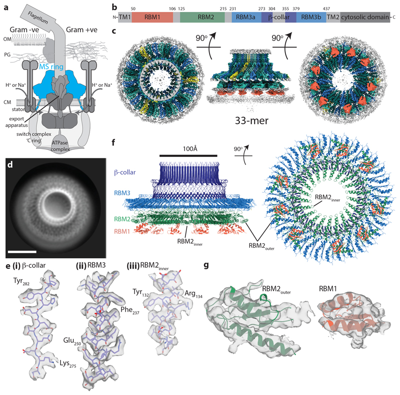
Figure 1. Overall structure of the flagellar MS ring.
a, Schematic showing the location of the MS ring (blue) within the bacterial flagellum. b, Cartoon representation of the domain structure of FliF. c, Composite 3D cryo-EM reconstruction with different symmetries applied within masks (see methods). Regions occupied by RBM2 and RBM3 for each chain are similarly coloured in an alternating scheme, with the exception of chains for which only RBM3 can be seen (yellow). Regions assigned to 9 RBM1 domains are indicated in red as connectivity cannot be definitively assigned. d, Representative 2D class of cross-linked FliF complexes on graphene oxide surface. Scale bar, 100Å. e, Representative density for regions where de-novo building of protein domains was possible in (i, ii) the C33 averaged RBM3-region map and (iii) the C21 averaged RBM2inner-region map. f, Final model for the 33mer FliF, coloured as in (b). g, Representative density for docking of the RBM2outer and RBM1 domains.
FliF forms rings of mixed internal symmetry
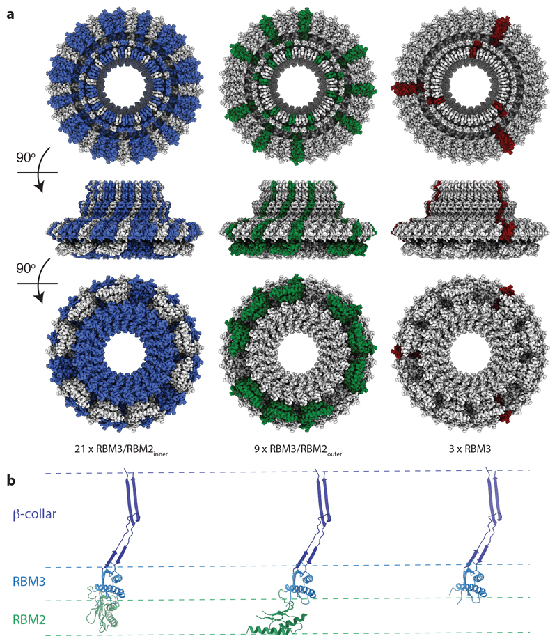
In order to better understand how a single protein could perform multiple different roles, we collected single-particle cryoEM data (Extended Data Fig. 1) from an over-expressed form of the S. Typhimurium MS ring (FliF). Analysis of near top-down views after 2D classification (Fig. 1d) revealed a periodicity at the extremity of the largest ring consistent with > 30 subunits, rather than the expected 25-27. Ab-initio reconstructions and 3D-classifications were performed using a variety of imposed symmetries, but initially only a C33 reconstruction produced an interpretable map. Further refinement of this model led to a 2.6 Å resolution volume (Fig 1c, e, f; Supplementary Table 1) in which 33 copies of residues 231-438 of FliF, corresponding to the RBM3/β-collar, were built de novo (Fig. 1e). However, all other densities within the C33 volume could not be interpreted as protein, suggesting either high levels of disorder or different symmetries (Extended Data Fig. 2a). Further refinements in lower symmetries led to a 2.9 Å resolution C21 reconstruction (Fig. 1c, e, f; Supplementary Table 1) of the ring below the C33 ring, in which residues 125-222, corresponding to RBM2, could be built, and ~4.5 Å resolution densities consistent with a further nine copies of RBM2 decorating the outside of the 21-fold symmetric RBM2inner ring (Fig. 1g). Underneath each copy of RBM2outer is a smaller density (~6 Å resolution) with structural features consistent with a homology model for RBM1 (Fig. 1g, RBM1 homology model built based on SctJ from 6duz 24). Although it is likely this domain pairs with the RBM2outer above, we do not see linking density to confirm this connectivity. The overall visible structure therefore contains twenty one copies of FliF contributing one RBM3 to the 33-fold ring and one RBM2inner to the 21-fold ring, nine copies of FliF contributing one RBM3 to the 33-fold ring, one RBM2outer and likely one RBM1, and three copies of FliF only contributing one RBM3 to the 33-fold ring (Fig. 2). The complex can therefore be broken down into four main structural assemblies: the 33-fold symmetric β-collar, the 33-fold symmetric RBM3 ring, the 21-fold symmetric RBM2inner ring and the decorating RBM2outer/RBM1 domains.
Figure 2. Domain rearrangements required to build the full assembly.
a, The locations of conformationally equivalent subunits within the assembly are highlighted; blue RBM3/collar/RBM2inner; green RBM3/collar/RBM2outer; maroon RBM3/collar/RBM2not observed. b, The three domain arrangements observed for RBM3/β-collar/RBM2 domains within the complex are shown with the RBM3/collar region aligned, coloured as in (Fig 1f).
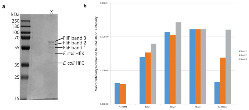
We see no clear protein density that accounts for the remaining three RBM2s, the remaining twenty four RBM1s, or any of the transmembrane helices and cytoplasmic portions. Proteomic analysis of a sample of purified FliF (Extended Data Fig. 3) only revealed loss of peptides from the C-terminal 120 residues (Supporting Data Sheet 1), corresponding to the C-terminal TM helix and cytoplasmic portion. We therefore assume that the missing domains are predominantly disordered and may localise to the weaker densities observed at the base of the structure. These densities include a ring of material close to the observed C-terminal residues, which is consistent with detergent micelle, and a column of weak density in the centre of the structure underneath the RBM2inner ring (Extended Data Fig. 2b) which may contain disordered RBM1 domains. We note that this column was observed in earlier, low resolution images of purified FliF and speculate that disordering of RBM1 may occur under the relatively harsh purification conditions and in the absence of other inner membrane components.
FliF monomer structures
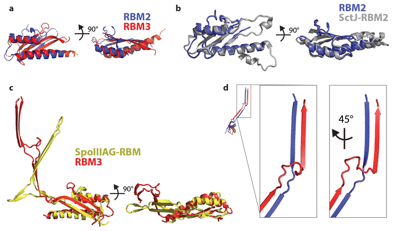
The enormous complexity of the 33-fold MS-ring means that there are a variety of monomer structures, with each of the 11 chains in the nominal asymmetric unit being unique in terms of relative domain orientation although these can be broadly grouped into three classes of arrangement (Fig. 2). Each subunit is made up of equivalent domains that match the predicted structural arrangement well (Fig. 1b). The density that corresponds to RBM1 fits a homology model based on domain 1 of the type III secretion system (T3SS) injectisome protein SctJ (6duz 24), with a βαββα topology. RBM2 and RBM3 are both canonical RBM domains with an αββαβ topology. Despite sequence identity of only 22%, they are structural homologues (Extended Data Fig. 4a). RBM2 is most closely related to a domain from SctJ, the injectisome basal body protein that forms a 24-fold symmetric concentric ring tethered to the inner membrane 25 (Extended Data Fig. 4b). RBM3 on the other hand is a closer structural homologue of the RBM domain from SpoIIIAG (5wc3), a sporulation protein from Bacillus subtilis that forms 30-fold symmetric rings in the periplasm 26 (Extended Data Fig. 4c). Both the SpoIIIAG RBM domain and RBM3 of FliF contain a long β-strand rich insertion between the first two β-strands of the RBM fold. The β-insertion (residues 273-379) essentially forms a pair of 2-stranded, anti-parallel β-sheets, one angled ~60° from the horizontal followed by an unusual vertical section. Residues 305-354 at the tip of the vertical strands are not observed, consistent with predictions of disorder in this region due to a high number of Pro, Ser and Thr residues. A prominent loop (residues 284-292) between the sections means that the strands cross over and their relative positioning is swapped between the angled and vertical sheets (Extended Data Fig. 4d). The C-terminus of RBM3 is the last observed residue in the structure and is directed towards the detergent micelle.
Comparing the monomers in the structure based on the RBM3/β-collar domains highlights the structural complexity of the rotor (Fig. 2b). The RBM2inner and RBM2outer positions are related by a 120° rotation and significant changes in the linker between RBM2 and RBM3 are required. However, even the positions of each RBM2inner domain display relative rotations of up to 9° in order to accommodate the symmetry mismatch between the 33-fold and 21-fold symmetric rings.
Assembly descriptions
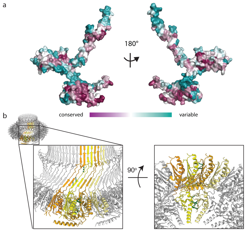
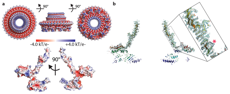
The total surface area buried in the FliF ring is enormous (217000 Å2), totalling 36 % of the available monomer surface. All of the interaction surfaces observed in the assembly are highly conserved, with areas of greatest variation occurring in surface loops and disordered regions (Fig 3a). Analysis of the electrostatic surface potential of the monomers reveals that the interaction surfaces are mostly hydrophobic, but patches of complementary charge are observed (Extended Data Fig. 5a). Further support for the interfaces observed comes from analysis of the co-evolution of residues pairs in the structure. Of the top 136 residues pairs identified as co-evolving using the Gremlin server 27, 30 are identified as being further than 5 Å apart in the monomer structure, but these are explained by inter-subunit packing interactions in the assembly (Fig. 3b).
Figure 3. Conserved or co-varying residues map to the inter-subunit interfaces.
a, Conservation of FliF between bacterial species is plotted on the surface of the monomer (ConSurf http://consurf.tau.ac.il) revealing that the monomer-monomer interfaces are the most conserved regions. b, Strongly co-varying residue pairs which do not form contacts within a single subunit (yellow) can all be explained by close contacts (green dotted lines) with neighbouring subunits (shades of orange).
The β-collar accounts for 77000 Å2 of the buried area and consists of 66 vertical β-strands (shear number of 0, corresponding to zero strand stagger) linked to 66 β-strands angled ~60° from the horizontal. In addition to numerous sidechain mediated hydrogen bonds, we observed a density connecting Arg373 and Lys275 from neighbouring subunits, consistent with a glutaraldehyde cross-link formed during the final purification stage before imaging (Extended Data Fig. 5b).
Both of the RBM3 and RBM2inner rings are constructed from the type of interface observed in other secretion system ring-forming motif structures, with the helices of one domain packing against the β-sheet of the neighbouring domain. However, when comparing the two interfaces, there is an ~6.5° rotation of one domain relative to the other in order to accommodate the different stoichiometries of the rings (Extended Data Fig. 6a). With the exception of the linkers between them, there is virtually no contact between the RBM3 and RBM2inner rings (~200 Å2 across the entire ring structure, Extended Data Fig. 6b). This is likely a reflection of the fact that the symmetry mismatch between the rings both prevents a consistent interaction surface and leads to a significantly smaller diameter for the RBM2inner ring (70 Å) compared with the RBM3 ring (140 Å) or the β-collar (100 Å). Contacts between the two mis-matched rings are instead via the RBM2outer subunits, with the C-terminal loop of one RBM2outer subunit tucking between two RBM3 subunits in the ring above (~250 Å2 buried per RBM2outer), while the second α-helix of the αββαβ motif bridges two RBM2inner subunits rings (~350 Å2 buried per RBM2outer). Additional contacts are observed between the C-terminus of an RBM1 domain and two of the RBM2inner subunits. However, the lower resolution of these portions of the structure suggests these are not tight contacts.
The mechanism by which such a complex arrangement of subunits and mixed symmetries could be built from a single protein chain is intriguing. It appears that the interaction surfaces of the RBM3 and RBM2 domains are primed to build rings of significantly different stoichiometry, and hence there is a need to build in flexibility for both small scale re-adjustments and the more extreme RBM2outer conformational re-arrangements. The majority of the structure is built from units containing two copies of the RBM2inner conformation and one copy of the RBM2outer conformation, This pattern is observed for three such units (contributing 9 RBM3s to the 33-fold ring and 6 RBM2inners to the 21-fold ring), at which point the pattern is broken by a subunit pair containing one copy of an RBM2inner conformation and one copy for which there is no visible RBM2 density. This completes one third of the structure and this pattern of packing is then repeated twice more.
FliF combines elements of sporulation and secretion system structures
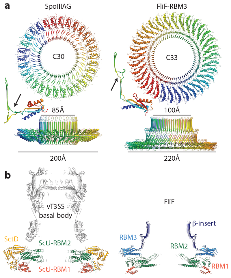
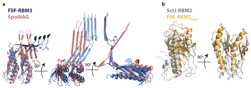
The closest structural homologue of the 33-fold RBM3 domain assembly is the SpoIIIAG protein from the sporulation system of B. subtilis 26, which forms a 30-fold symmetric structure utilising a very similar interaction surface to the RBM3 domains of FliF (Fig. 4a and Extended Data Fig. 7a). Strikingly, SpoIIIAG also contains a β-insertion that forms a 60-strand β-collar with a shear number of 0, and both proteins also share a feature of a short triangular insertion at the point the strands change direction to the vertical. Such vertical β -strands are highly unusual, but have also been observed in the outer membrane secretin structures of T3SS and type II secretion systems (T2SS) 25,28. Despite the strong similarities, there are significant differences between FliF and SpoIIIAG, most notably in the angle of the RBM domain to the β-collar.
Figure 4. Comparison to structurally or functionally homologous assemblies.
a, The closest structural homologue to the RBM3 portion of the FliF ring is the 30-mer B. subtilis protein SpoIIIAG (PDB-5wc3). A view from the outer-membrane side is shown above and from the side below, with a cartoon representation of a single, extracted, monomer also shown. A small beta-insertion structure is indicated (arrow on monomer structures). b, The virulence T3SS basal body is constructed from two protein chains in the MS-ring equivalent region, which both form 24-mer rings consisting of multiple RBM domains. Central sections of the Salmonella SPI-1 injectisome basal body (PDB-5tcr, LH panel) and the FliF ring (RH panel) show the striking similarity in overall shape despite fundamental differences in the chains and domain types used. They also show the 21-fold RBM2inner domains are very similarly arranged to the PrgK/SctJ-RBM2 24-fold ring, whilst the FliF-RBM1 and PrgK/SctJ-RBM1 domains are very differently arranged with respect to these.
The RBM2 domain is most closely related at both sequence and structural levels to the RBM2 domain of the SctJ family from the virulence T3SS injectisomes and again this homology extends to the ring structures formed (Fig. 4b). The inner-membrane proximal portion of an injectisome basal body is formed by two different proteins, SctD and SctJ. The inner SctJ ring has been shown to house the export gate structure of the secretion system in its central cavity 24,29 and forms a 24-fold symmetric ring from RBM1 and RBM2 domains 25. The interaction interface between neighbouring domains in the SctJ RBM2 ring is closely related to the FliF RBM2inner packing interaction (Extended Data Fig. 7b), although the copy number difference does lead to a small difference in the size of the cavity.
FliF can form different stoichiometric assemblies
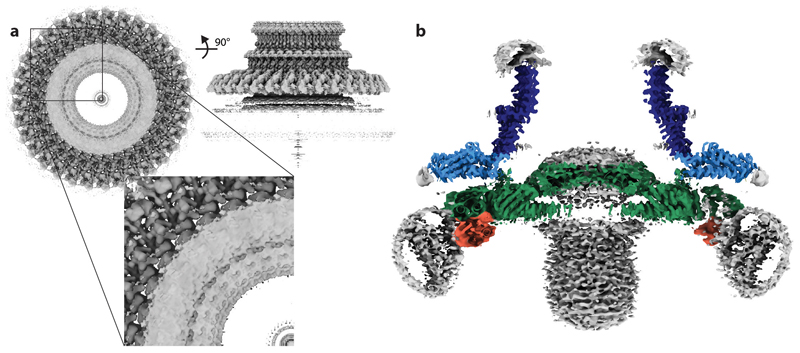
More detailed analyses of 3D classifications of the FliF particles imposing C3 symmetry revealed a subset of particles in which the C33 features were subtly broken. Further refinement of these particles in C1 symmetry, only allowing small, local angular movements away from the originally assigned orientations, revealed that they corresponded to a 34-fold symmetric RBM3/β-collar structure. Further refinement of this particle set with different symmetries revealed that they corresponded to a FliF 34mer with a C34 RBM3/β-collar region and a C22 RBM2inner region surrounded by ten densities that correspond to the RBM2outer/RBM1 domain pairs (Fig. 5a, Extended Data Fig. 8, Supplementary Table 2). Again no density was observed for the final two copies of RBM2 or for twenty four copies of RBM1.
Figure 5. The flagellar MS ring is structurally heterogenous.
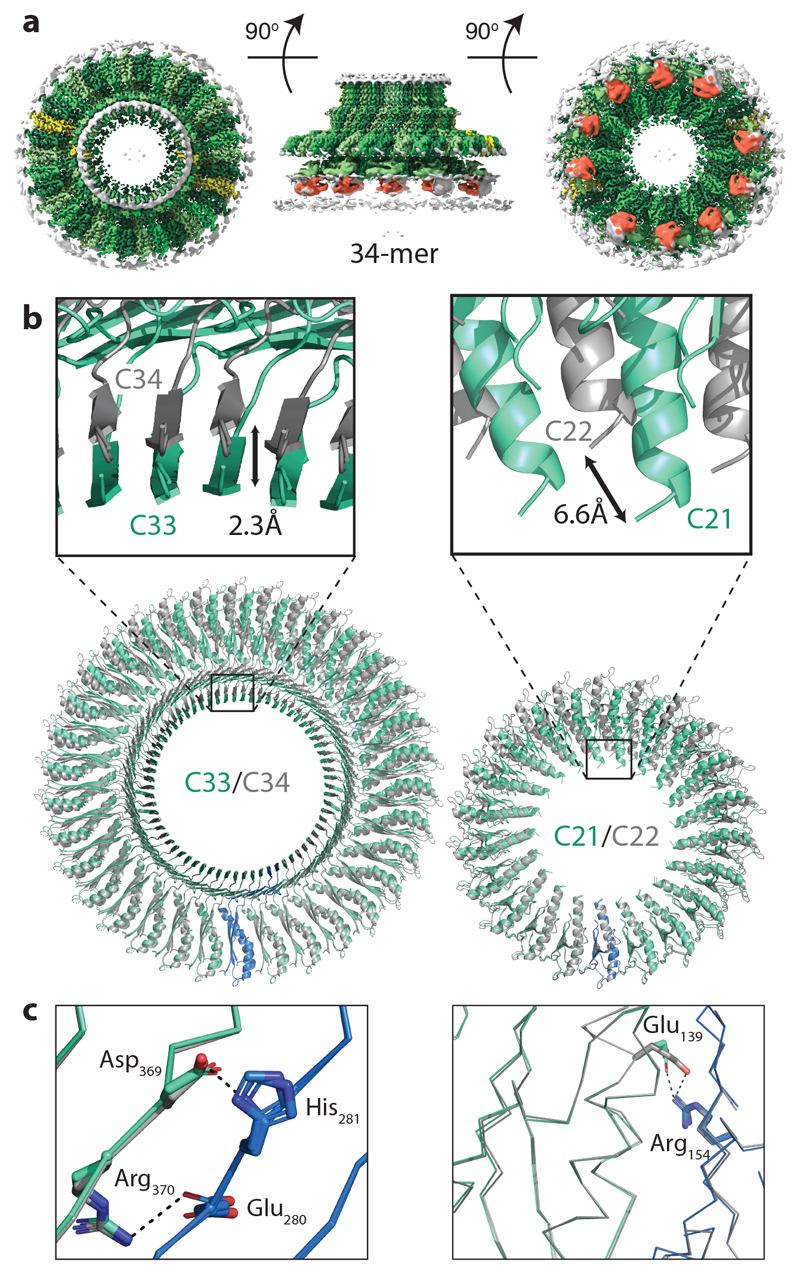
a, Composite 3D cryo-EM reconstruction from a 34-fold stoichiometric subset of particles. C34 symmetry is applied within the RBM3 region, C22 within the RBM2inner region and C2 symmetry applied elsewhere. The colour scheme mimics that of Figure 1c. b, Comparison of the C33/C34 and C21/C22 regions by overlaying the complete rings using a single chain reveals the subtle differences in the sizes of the respective ring-like assemblies built. c, Despite assembling to form rings of different symmetries, the specific interactions from which they are built are entirely conserved, including potential salt bridges, in both the C33 (cyan and blue)/C34 (grey) rings (left hand panel) and the C21 (cyan and blue)/C22 (grey)rings (right hand panel).
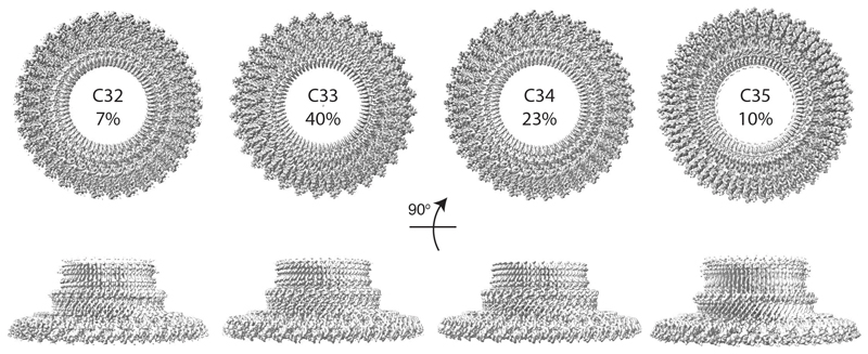
The MS ring is therefore capable of assembling into rings of differing stoichiometries. Analysis of the interfaces buried in the FliF 34mer revealed that only very subtle changes are needed to build the alternate stoichiometry (Fig. 5b, c). The interfaces used in the 33-fold RBM3/β-collar ring are identical to those in the 34-fold RBM3, maintaining all of the bonding interactions, including salt bridges (Fig. 5c). A similar pattern is observed for the RBM2inner rings. Although the changes are subtle, when propagated around the number of copies in the ring, they do make a difference to the diameter of each ring, with a 2.3 Å (2 %) increase seen in the RBM3/β-collar ring and a 6.6 Å (9 %) increase observed for the RBM2inner ring. The most significant difference between the two structures exists in the RBM2outer/RBM1 domain pairs, where an extra copy is observed. However, the mode of packing of the RBM2outer/RBM1 against the RBM2inner ring and the basic 2:1 (RBM2inner:RBM2outer) building block is conserved. It is worth noting that the symmetries of the two main rings always leave twelve copies of the monomer which don’t contribute to RBM2inner and twenty four copies of RBM1 for which we see no density, although the significance of these observations is currently unclear. Further supervised 3D classification was also performed in C1 symmetry, which confirmed that the majority of the particles partitioned into the C33 and C34 classes (40% and 23% respectively), with 7% and 10% ending up in C32 and C35 classes respectively (Extended Data Fig. 9, Supplementary Table 3).
The MS-ring as structural adaptor
The structural heterogeneity observed in this study may seem surprising for a core component of such a fundamental cellular structure, but is not unprecedented in flagellar/injectisome systems. Firstly, recent Cryo-EM analyses of injectisome structures 30,31 have revealed that the absence of the export gate components can lead to production of basal bodies with only 23 copies of the SctD/J proteins, rather than the fully assembled 24 copies. Therefore it is possible that the heterologous expression of FliF in the absence of the export gate has led to a shift to smaller stoichiometries. However, stoichiometric heterogeneity has also previously been observed for the S. Typhimurium C-ring 20–22. The C-ring is a large cytoplasmic structure that assembles on to the MS-ring via a mechanism in which the N-terminal domain of the first C-ring protein, FliG, folds around two helices at the C-terminus of FliF 11,12. The other domains of FliG then recruit the other C-ring components, FliM and FliN 32–35, as well as providing the interaction surface for the stator complexes that generate torque 36,37. The MS-ring/C-ring junction is therefore critical for flagellar function. The large diameter (~ 450 Å in S. Typhimurium) and strong periodicity led to robust estimates of C-ring stoichiometry in both fully assembled flagella and in reconstituted MS-ring/C-ring structures. These studies all revealed clear stoichiometric heterogeneity, with subunit numbers ranging between 32 and 36 copies 20–22, but with 34 copies being the most commonly observed. We therefore think it likely that the heterogeneity is a genuine phenomenon, but that lack of the export gate may tip the balance from 34-fold to 33-fold being most probable.
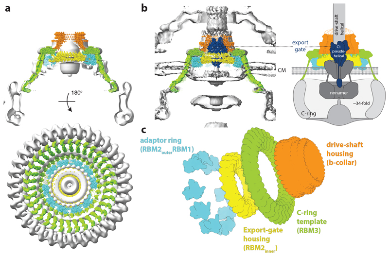
The apparent mismatch between the C-ring and the originally proposed 25/26-fold symmetry of the MS-ring had led to models whereby symmetry mismatch between the two rings was important for function. Our structures of FliF demonstrate that the stoichiometry of the MS-ring and the C-ring are likely matched, suggesting that the entire C-ring stoichiometry is nucleated by the stoichiometry of the MS-ring. Fitting of FliF into the only available structure of a purified flagellum with an intact C-ring 20 demonstrates the perfect fit of the dimensions of the object within the MS-ring portion of the volume, despite this region of the volume being averaged with 25-fold symmetry (Fig. 6a). Although we do not observe the C-terminal residues of FliF in our structure, the positioning of the RBM3 domains on the outside of the ring mean they are correctly placed to reach down to the FliG ring underneath the membrane. This observation was confirmed by placing the FliF structure into a subtomogram average of in situ flagella from Plesiomonas shigelloides (Fig. 6b) 38. Interestingly, this placement also provides further insights into other roles the symmetric complexity of the MS-ring may play in acting as a single chain structural adaptor molecule at the centre of the system (Fig. 6c). At the top end of the structure, the β-collar acts as housing for the proximal flagellar rod. A mutation in FliF (Asn318Thr) that weakens interactions between the basal body and the flagellum maps to the β-collar, and revertant mutations that rescue motility map to components of the proximal rod that forms the flagellar drive-shaft 39. Immediately below this, the RBM3 domains of the structure, and hence the cytoplasmic C-termini, have the 33/34-fold symmetry required to assemble the C-ring underneath the inner membrane. The RBM2inner domains, on the other hand, form the 21/22-fold symmetric ring that is seen to house the export gate in the homologous injectisome structures 24,25,30. The highly conserved dimensions of the export gate 40, compared to the large diversity in C-ring size between bacterial species, likely drives the requirement for symmetry mismatch between the different domains of FliF. Despite this, crude docking of a structure of the export gate into FliF highlights that the subtle differences in size between the central pore of the flagellar RBM2inner 21/22mers and the equivalent 24mer SctJ injectisome ring means there may be some flexibility in the details of how the export gate is accommodated between the two systems. Such differences preclude atomic modelling of an MS-ring/export gate complex. However, whether they reflect true differences between the systems, perhaps related to the altered inner membrane curvature observed in tomographic studies, or are related to different assembly states in the presence and absence of export gate, as has been recently shown for the injectisome 30,31, remains to be clarified. Clearly high resolution structures of fully assembled complexes will be required to fully answer these questions.
Figure 6. The MS-ring as a structural adapter.
a, A model for the 34-mer MS-ring, coloured to highlight the different structural regions, is placed in the single particle reconstruction of the S. Typhimurium flagellar basal body (grey) (EMD-1887), showing the good match in overall shape and links to the 34-fold symmetric C-ring. The 34-mer FliF was built in the map shown in Figure 5a and extended to the C-terminus using a continuous helix of the correct length, ending in a homology model based on the crystal structure of residues 523-559 of Helicobacter pylori FliF (PDB: 5wuj). b, The FliF model (coloured as in (a)) is shown placed in a P. shigelloides tomographic volume (EMD-10057) and a model for the export gate complex (blue) (PDB-6r69) is then docked within FliF. The panel on the right is an update of the cartoon from Figure 1a, using this colour scheme. c, Exploded diagram of FliF coloured to emphasise the roles the different symmetries play in adapting between components within the flagellar assembly.
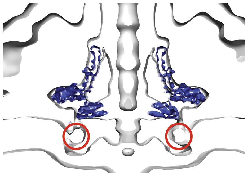
In both systems a nonameric protein complex, termed the FlhA ring in flagella, forms a cytoplasmic ring directly below the basal body, with its transmembrane domains presumed to occupy the membrane underneath the RBM2 ring 30,41–43}. It is noteworthy that a mutation in the β-sheet of the RBM2 domain of FliF (deletion of residues 174 and 175) can be suppressed by secondary mutations in the TM domains of FlhA 44, suggesting some ability for changes in the stability of one ring to be compensated by changes in the other. The space likely occupied by the FlhA TM domains overlaps with the disordered column of density in our structure that we ascribe to disordered RBM1 domains. We therefore propose that the RBM1 domains may fold and occupy the space around the FlhA in the assembled basal body, perhaps in the location of a ring of membrane proximal density observed in the tomogram of the P. shigelloides flagellum (Extended Data Fig. 10). Again, high resolution structures of higher order assemblies will be needed to address this.
Conclusion
This study has provided a near-atomic resolution view of the MS-ring of the bacterial flagellar rotor. The structures reveal unexpected symmetries and an unprecedented level of structural heterogeneity for a homo-oligomeric assembly. The symmetry mismatches within the structure demonstrate how the MS-ring is able to bridge multiple different structural and functional units within the flagellar basal body utilising a single protein chain (Fig. 6c). The explicit linking of the MS-ring stoichiometry to that of the C-ring introduces new questions of how rotors of different sizes in different species of bacteria can be reconciled with this model, especially given the constraints that the need to house the T3SS in the centre of the structure places on the system. Will FliF provide yet more surprises or will other adaptor proteins play a role?
Materials & Methods
Chemicals were from Sigma-Aldrich unless otherwise specified. Detergents n-dodecyl-maltoside (DDM), Lauryl Maltose Neopentyl Glycol (LMNG) and amphipol A8-35 were from Anatrace.
Protein expression
The FliF expression plasmid was designed based on the pKOT105 plasmid from Ueno et al 13. Briefly, the fliF gene from Salmonella enterica serovar Typhimurium was amplified using Q5 polymerase (NEB) and inserted into the BamHI site of pET-3b (Merck) using NEBuilder HiFi Master Mix (NEB). FliF was expressed in Escherichia coli BL21 (DE3) pLysS. 20 ml of overnight culture grown at 37 °C was used to inoculate 2 L of LB media, grown at 37 °C until OD600 reached 0.5 and induced with 0.5 mM IPTG at 30 °C for 4 hours. Cells were harvested by centrifugation at 5000 x g for 10 minutes and frozen at -20 °C until use.
Protein purification
Frozen cell pellet was resuspended in 40 ml of lysis buffer (50 mM Tris pH 8, 50 mM NaCl, 5 mM EDTA) and lysed by 3 passes through an Emulsiflex C5 homogeniser (Avestin) at 10,000 psi. After centrifugation at 20,000 x g for 20 min to remove cell debris, cell membranes were collected by ultracentrifugation at 186,000 x g for 1 hour. Collected membranes were dissolved in 40 ml of alkaline buffer (50 mM CAPS pH 11, 5 mM EDTA, 50 mM NaCl, 1 % (w/v) DDM) at 4 °C for 1 hour. Undissolved material was removed by centrifugation at 20,000 x g for 20 minutes. Solublised FliF was then pelleted by ultracentrifugation at 143,000 x g for 1 hour. Pelleted FliF was resuspended in 2 ml of resuspension buffer (25 mM HEPES pH 8, 50 mM NaCl, 0.1 % (w/v) DDM). FliF ring assemblies were then separated from FliF monomers by loading the resuspended FliF on a 15-40 % (v/v) sucrose gradient prepared using gradient buffer (10 mM HEPES pH 8, 5 mM EDTA, 0.02 % (w/v) DDM). The gradient was then centrifuged at 25,000 rpm for 15.5 hours using SW55Ti rotor. Gradient fixation (GraFix 45) was used to improve stability of FliF ring assembly by addition of a 0-0.2 % (v/v) glutaraldehyde gradient to the sucrose gradient. Selected fractions of the sucrose gradient containing FliF ring assemblies was dialysed against dialysis buffer (25 mM Tris pH 8, 50 mM NaCl, 0.02 % (w/v) DDM) overnight to remove sucrose and concentrated to the appropriate concentration using a 300 kDa MWCO concentrator. For FliF preparations using Triton-X100, the same concentration of Triton-X100 was used in place of DDM.
Amphipol trapping of GraFix crosslinked FliF purified in DDM was performed by addition of amphipol A8-35 to 0.8 mg/ml FliF at 1:3 (w/w) ratio. Excess detergent was removed by the addition of BioBeads (BioRad) at 20-fold excess of detergent mass. Excess amphipol was removed by buffer exchanging into detergent-less dialysis buffer using a 100 kDa MWCO concentrator.
Cryo-EM sample preparation and imaging
FliF samples were added to 300 mesh R1.2/1.3 Quantifoil Cu grids coated with graphene oxide substrate, blotted using Vitrobot Mark IV (FEI) and frozen with liquid ethane. The grids were imaged using a 300 keV Titan Krios microscope (FEI) with an energy filter and Gatan K2 detector (Gatan). Data were collected with a pixel size of 0.822 Å and an exposure of 1.5 e/Å2/frame for 32 frames. For the sample in Triton X-100, 6111 movies were collected. For the sample in DDM, 9173 movies were collected. For the sample in amphipol A8-35, 11538 movies were collected.
Cryo-EM data processing
Micrographs were initially processed in real time using the SIMPLE pipeline 46, using SIMPLE-unblur for motion correction, SIMPLE-CTFFIND for CTF estimation and SIMPLE-picker for particle picking. Following initial 2D classification in SIMPLE to remove poor quality particles, all subsequent processing was carried out in in RELION-3.0 47. Particles were re-extracted using a 432 x 432 pixel box from micrographs that had been re-processed using the MotionCor2 48 implementation in RELION-3.0, with CTF estimation by CTFFIND4 49.
Initial processing of the Triton-X100 extracted particles produced 2D classes with close to top down views that allowed preliminary counting of the subunits around the perimeter of the object, although the lack of purely top down views prevented unambiguous assignment. 27435 particles were selected after classification and used to generate ab initio initial models with C33 and C34 symmetry. 3D classification was carried out with C33 and C34 symmetries applied and the C33 job produced a class containing 15634 particles that refined to 3.8 Å resolution using gold standard refinement. Reclassification of the original particles produced a 19520 particle set that led to a 3.1 Å resolution map following Bayesian polishing 50 and per-particle CTF refinement. This allowed de novo model building of the RBM3/β-collar domains (residues 231-438) but all other regions of the map remained untraceable. Attempts at reconstructing with lower symmetry were hindered by the low particle number.
A larger, DDM-extracted, dataset was collected that contained 188007 particles after 2D classification. 3D classification applying C33 symmetry resulted in one good class with 106745 particles which were then used in a C1 symmetry refinement. This produced density in the ring below the C33 ring with a clear periodicity that could be counted as C21. Refinement of this particle set with the common symmetry of C3 applied produced a 3.3 Å resolution map, following Bayesian polishing and CTF refinement, that revealed an RBM fold in the 21-fold symmetric ring. However, the quality of this portion of the map was not sufficiently detailed to allow de novo model building. As the proportion of particles that produced a sub-3.5 Å resolution map were similar between the two different detergent extractions, and the maps produced were indistinguishable, we created a combined dataset containing the post-2D classification particles from the Triton-X100 and DDM extractions and a small dataset from a DDM extracted sample that had been exchanged into amphipol A8-35. This dataset, containing 273493 particles was subjected to 3D classification applying C3 symmetry, using the DDM-only model low pass filtered as a reference. After two rounds of 3D classification, two good classes were produced, containing 126285 and 59163 particles. The first of these classes refined to a pure C33 object in the RBM3 region, but the second class produced a map with ~11.3 subunits per “asymmetric unit” in the C3 symmetry. We therefore re-refined this class applying C34 symmetry, which produced a 3.3 Å resolution gold standard map. Refinement of the “C34” particles in C1 produced periodicity in the ring below the RBM3 ring consistent with C22 symmetry.
Due to the increased complexity of the sample, we collected a large A8-35 exchanged dataset and created a composite Triton-X100/DDM/A8-35 dataset containing 449142 particles after 2D classification. These particles were then subjected to a supervised 3D classification in C1, using C33 and C34 maps as references, producing classes with 308536 and 140606 particles respectively. The C33 class was subjected to a further round of classification, producing a good class with 175233 particles that was refined in C3 to an overall resolution of 2.9 Å following Bayesian polishing and CTF refinement. Further focused classification and refinement of the C33 particles with a mask around the RBM3/β-collar region, and with C33 symmetry applied, produced a 2.6 Å resolution map from 77849 particles. Further focused classification and refinement of the C33 particles with a mask around the RBM2inner region, and with C21 symmetry applied, produced a 2.9 Å resolution map from 84797 particles. Attempts to improve the resolution of the RBM2outer/RBM1 region through particle subtraction, multi-body refinement and local averaging were unsuccessful. Initial refinements of the entire object produced maps with nine strong copies of the RBM2outer/RBM1 pair and weaker density in the gaps between copies 3 and 4, 6 and 7 and 9 and 1. This weaker density was consistent with being a superposition of two copies of the RBM2outer/RBM1 density. However, the spacing of these domains was such that these gaps could not accommodate a full RBM2outer/RBM1 pair without structural rearrangement, and we reasoned that the density observed could be produced by rotational misalignment of a subset of the particles producing “ghost” density from the strong domains. In order to test this, we masked around the nine strong domain pairs and used this mask in a focused refinement, with the logic that if extra copies were genuinely ordered they would appear in the final, unmasked, map. This was not found to be the case. The C34 class was refined with C2 symmetry applied and produced a 3.3 Å resolution map after Bayesian polishing and CTF refinement. Further focused refinement of the C34 particles with a mask around the RBM3/β-collar region, and with C34 symmetry applied, produced a 2.8 Å resolution map. Further focused classification and refinement of the C34 particles with a mask around the RBM2inner region, and with C22 symmetry applied, produced a 3.1 Å resolution map from 87107 particles. Similar analysis of the RBM2outer/RBM1 region was applied as in the C33 refinements, with similar results, but in this case ten copies of the domain pair could be placed.
Further, supervised, 3D classification of the combined particle set was carried out in C1 using initial models of the RBM3/collar region with C32 (7%), C33 (40%), C34 (23%), C35 (10%) and C36 (20%) symmetries. The C32 particle set was refined after Bayesian polishing and CTF refinement to 3.3 Å resolution for the RBM3/collar and a C35 particle set that was refined after Bayesian polishing and CTF refinement to 4.5 Å resolution for the RBM3/collar. However, all attempts to determine the stoichiometry of the RBM2inner region failed, presumably due to the small number of particles in each subset. The 20% that went into the C36 class produced low resolution volumes that displayed clear signs of over-fitting artefacts, suggesting that damaged and low resolution particles accumulated in this class. The relative contributions of particles from different detergent extractions was equivalent across the 4 good classes, consistent with the different stoichiometries having pre-existed in the membrane prior to extraction rather than reflecting rearrangement during extraction.All processing statistics are summarised in Supplementary Tables 1-3.
Model building and refinement
A monomer model for the RBM3 and the β-collar (residues 231-438) was built manually in Coot 51 using the 2.6 Å resolution map with C33 symmetry applied, assembled into a 33-fold model, and refined using phenix.real_space_refine 52. A monomer model for RBM2 (residues 125-222) was built manually in Coot using the 2.9 Å resolution map with C21 symmetry applied, assembled into a 21mer of the RBM2inner region and refined using phenix.real_space_refine. The whole 33mer was assembled from these two structures in the 2.9 Å resolution map with C3 symmetry applied. The two main rings were joined by manually building the linkers in Coot. Nine copies of the high resolution RBM2 domain were placed manually in the RBMouter domain densities of a 4 Å lowpass filtered version of the C3 map, and rigid body refined. Nine copies of a RaptorX generated homology model of RBM1 (residues 50-106) were manually positioned in the density underneath the RBMouter domains and rigid body refined. The completed 33mer was refined with phenix.real_space_refine, using the higher resolution C33 and C21 structures as reference models. The RBM3/β-collar monomer built in the C33 map was used to assemble a 34-fold model in the 2.8 Å resolution map with C34 symmetry applied, and was refined using phenix.real_space_refine. A 22-fold RBM2inner model was assembled in the 3.1 Å resolution map with C22 symmetry applied, using the RBM2 monomer built in the C21 map, and was refined using phenix.real_space_refine. The whole 34mer was assembled from these two structures in the 3.3 Å resolution map with C2 symmetry applied. The two main rings were joined by manually building the linkers in Coot. Ten copies of the RBMouter/RBM1 domain pairs from the 33mer model were placed manually in the appropriate densities of a 4 Å lowpass filtered version of the C2 map, and were rigid body refined. The completed 34mer was refined with phenix.real_space_refine, using the higher resolution C34 and C22 structures as reference models. All models were validated using Molprobity 53. All refinement and validation statistics are summarised in Supplementary Tables 1-3. Conservation analysis was carried out using the Consurf server 54. Figures were prepared using Pymol (The PyMOL Molecular Graphics System, Version 2.0 Schrödinger, LLC) and ChimeraX 55. Buried surface area was calculated using QtPISA 56.
SDS-PAGE
Samples were taken throughout the purification of FliF and analysed by SDS-PAGE using 12% (w/v) handcast polyacrylamide gels run in tris-glycine buffer. The gels were stained with InstantBlueTM (Expedeon) to determine the presence of FliF and assess sample purity.
Sample preparation for mass spectrometry analysis
Purified, non-crosslinked FliF was analysed by Blue NativePAGE (NativePAGETM Novex® Bis-Tris gel system with 3-12% Bis-Tris gels (Invitrogen by Thermo Fisher Scientific), stained with Coomassie Brilliant Blue G-250 dye). This revealed a band at a molecular weight of >1 MDa. This band was cut from the gel and subsequently analysed by SDS-PAGE (12% handcast polyacrylamide gel run in tris-glycine buffer, stained with InstantBlueTM (Expedeon)). The resulting five bands on the SDS-PAGE gel were excised and sent for mass spectrometry analysis at the Advanced Proteomics Facility (Department of Biochemistry, University of Oxford).
Evolutionary covariance analysis
Covarying residues in FliF were analyzed using the GREMLIN web-server 27, using a sequence alignment generated by Jackhmmer with an E-value of 1E-06 and a gap exclusion of 75%. This generated an MSA of 2760 sequences for analysis and the results were fed into GREMLIN-BETA for mapping onto the PDB coordinates. The results of the GREMLIN analysis are available publicly at: http://www.openseq.org/sub.php?id=1572969959&uid=1498573696.
Extended Data
Extended Data Fig. 1. Structure determination of 33mer.
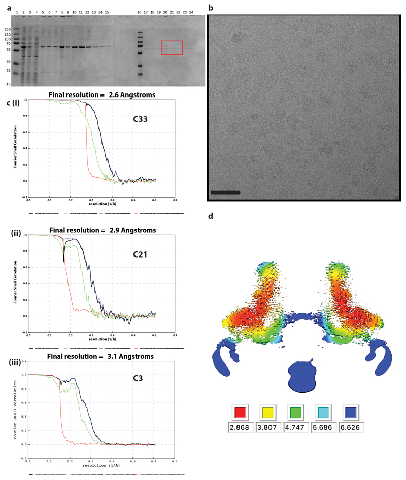
a. SDS-PAGE of samples taken throughout purification of FliF in DDM. Lanes contain (1, 16) PageRuler Markers (2) whole cell lysate (3) supernatant from low speed spin (4) supernatant from high speed spin (5) solubilised membranes (6) supernatant from second low speed spin (7) supernatant from second high speed spin (8) resuspended pellet from second high speed spin (9-15 and 17-20) fractions from top to bottom of sucrose gradient post-high speed equilibration. Note – this gel shows samples from sucrose gradient without glutaraldehyde run in parallel with tubes containing glutaraldehyde. The fractions equivalent to those indicated (red box) were selected from the cross-linked gradients and used for structural analysis. b. Example micrograph (1.5 μm defocus) of cross-linked FliF on a graphene oxide surface. Scale bar 500Å c. FSC curves from PostProcessing in RELIONv3.0 for volumes calculated in (i) C33, (ii) C21 and (iii) C3 respectively. d. Slab through C3 volume coloured by local resolution as estimated using RELIONv3.0.
Extended Data Fig. 2. 33-fold symmetry does not resolve lower ring detail.
a. Volume generated by refinement in C33 shows lack of detail in RBM2inner region below, later explained by C21 symmetry in this region. b. Slab through central section of composite C33/C21/C3 volume reveals layered density derived from the detergent micelle at the periphery of the RBM3 ring and a central column of density below the C21 ring that presumably results from density associated with the 24 copies of RBM1 that are not located elsewhere in the map, the N-terminal trans-membrane helices attached to these and associated detergent.
Extended Data Fig. 3. Proteomic analysis reveals limited clipping at extreme C-terminus of FliF.
a. Purified, non-crosslinked S. Typhimurium FliF was run on blue native PAGE, then the gel band corresponding to the FliF complex was cut out and run on SDS-PAGE (lane marked X). The SDS-PAGE bands were cut out and mass spectrometry was used to identify the protein. The identity of each band is indicated on the gel. b. The three S Typhimurium FliF bands all produced peptides spread throughout the FliF amino acid sequence (i.e. from residues 2 to 560/552), however the two lighter bands had a lower intensity of peptides from the sequence post the folded RBM3 domain suggesting these bands differ in trimming of the extreme C-terminus beyond the structured region.
Extended Data Fig. 4. Comparisons of individual RBM domains.
a. Overlay of RBM2 and RBM3 domains of FliF (chain A), rmsd of 2.3 Å over 78 Cα. b. Superposition of the RBM2 domain of FliF on the closest structural homologue – the RBM2 of SctJ, rmsd of 1.1 Å over 79 Cα c. Superposition of the RBM3 domain of FliF on the SpoIIIAG RBM domain, rmsd of 2.3 Å over 80 Cα. The beta-insertions are not used to derive the superposition and the different relationship between the RBM domains and these inserts can therefore be appreciated. d. The N-terminal (blue) and C-terminal strands (red) of the beta-insert cross at the transition between tilted and vertically oriented strands.
Extended Data Fig. 5. Structural Observations.
a. The Electrostatic potential is mapped onto the surface of the FliF assembly (upper panel) and monomer using APBS within PyMol, revealing that the overall object is highly charged whilst the monomer interfaces are largely hydrophobic. b. A putative glutaraldehyde cross-link (marked with an asterisk) is observed in the beta-collar region of FliF.
Extended Data Fig. 6. Building the C21 portion of the structure.
a. Superposing a pair of neighbouring RBM3 domains on to a pair of neighbouring RBM2inner by aligning the first domain shows the rearrangements driven by the C33 versus C21 packing. b. The RBM2outer domains provide the major contact between the RBM2inner and RBM3 rings adapting between the C21 and C33 symmetries.
Extended Data Fig. 7. Subtle differences in RBM domain packing drives different assemblies.
a. Superposing a pair of neighbouring RBM3 domains on to a pair of neighbouring SpoIIIAG RBM domains by aligning the first domain shows the subtle alteration in packing needed to form the C33 rather than C30 assemblies. b. Superposing a pair of neighbouring RBM2inner domains on to a pair of neighbouring SctJ RBM2 domains by aligning the first domain shows the subtle alteration in packing needed to form the C21 rather than C24 assemblies.
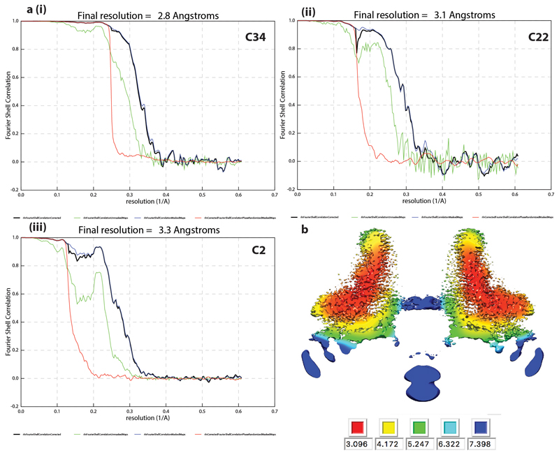
Extended Data Fig. 8. Structure determination of 34mer.
a. FSC curves from PostProcessing in RELIONv3.0 for volumes calculated in (i) C34, (ii) C22 and (iii) C2 respectively. b. Slab through C2 volume coloured by local resolution as estimated using RELIONv3.0.
Extended Data Fig. 9. Supervised 3D classification reveals assembly diversity.
Distribution of particles between different symmetries in the RBM3 ring/β-collar region following supervised 3D-classification. 20% of particles were allocated to a C36 class, but the volume was uninterpretable from this class and presumably reflected damaged particles / particles with a variety of other symmetries.
Extended Data Fig. 10. Putative location of missing RBM1 domain in tomogram.
A slab through the centre of the P. shigelloides flagellar tomogram (grey surface; EMDB 10057) with the FliF C34 volume (blue surface) placed. The density of appropriate volume for the currently unresolved RBM1 domains is highlighted with red circles.
Supplementary Material
Acknowledgements
We thank E. Johnson and A. Costin of the Central Oxford Structural Microscopy and Imaging Centre for assistance with data collection. H. Elmlund (Monash) is thanked for access to SIMPLE code ahead of release. We thank Morgan Beeby (Imperial College) for access prior to publication, to the P. shigelloides tomographic volume. The Central Oxford Structural Microscopy and Imaging Centre is supported by the Wellcome Trust (201536), The EPA Cephalosporin Trust, The Wolfson Foundation and a Royal Society/Wolfson Foundation Laboratory Refurbishment Grant (WL160052). Work in SML’s lab is supported by Wellcome Trust Investigator (100298) and Collaborative awards (209194) and an MRC Programme Grant (MR/M011984/1). L.K. is a Wellcome Trust PhD student (1009136).
Footnotes
Data Availability
The data that support the findings of this study are available from the corresponding author upon reasonable request. Cryo-EM maps have been deposited with the EMDB with the following accession codes: EMD-10143, EMD-10145, EMD-10146, EMD-10147, EMD-10148, EMD-10149, EMD-10560, EMD-10561. Atomic coordinates have been deposited with the PDB with the following accession codes: 6SCN, 6SD1, 6SD2, 6SD3, 6SD4, 6SD5, 6TRE.
Author Contributions
SJ & SML designed the project, interpreted the data and wrote the first draft of the paper. SJ analysed the data. YHF cloned, expressed and purified protein samples, and made and optimised EM grids. JCD made and screened grids. JCD & SML collected the EM data. EF expressed and purified samples and made EM grids. LK made constructs and performed preliminary purification experiments. All authors commented on drafts of the manuscript.
Competing Interests
The authors declare no competing interests.
References
- 1.Leeuwenhoek A. Observation, communicated to the publisher by Mr Anthony van Leewenhoeck, in a Dutch letter of the 9 Octob. 1676 here English'd: concerning little animals by him observed in rain-well-sea and snow water; as also in water wherein pepper had lain infused. Phil Trans. 1677;12:821–831. doi: 10.1098/rstl.1677.0003. [DOI] [Google Scholar]
- 2.Berg HC. The rotary motor of bacterial flagella. Annu Rev Biochem. 2003;72:19–54. doi: 10.1146/annurev.biochem.72.121801.161737. [DOI] [PubMed] [Google Scholar]
- 3.Erhardt M, Namba K, Hughes KT. Bacterial nanomachines: the flagellum and type III injectisome. Cold Spring Harb Perspect Biol. 2010;2 doi: 10.1101/cshperspect.a000299. a000299. [DOI] [PMC free article] [PubMed] [Google Scholar]
- 4.Macnab RM. How bacteria assemble flagella. Annu Rev Microbiol. 2003;57:77–100. doi: 10.1146/annurev.micro.57.030502.090832. [DOI] [PubMed] [Google Scholar]
- 5.Chen S, et al. Structural diversity of bacterial flagellar motors. EMBO J. 2011;30:2972–2981. doi: 10.1038/emboj.2011.186. [DOI] [PMC free article] [PubMed] [Google Scholar]
- 6.Magariyama Y, et al. Very fast flagellar rotation. Nature. 1994;371:752. doi: 10.1038/371752b0. [DOI] [PubMed] [Google Scholar]
- 7.Sowa Y, Berry RM. Bacterial flagellar motor. Q Rev Biophys. 2008;41:103–132. doi: 10.1017/S0033583508004691. [DOI] [PubMed] [Google Scholar]
- 8.Berg HC. The flagellar motor adapts, optimizing bacterial behavior. Protein Sci. 2017;26:1249–1251. doi: 10.1002/pro.3055. [DOI] [PMC free article] [PubMed] [Google Scholar]
- 9.Francis NR, Sosinsky GE, Thomas D, DeRosier DJ. Isolation, characterization and structure of bacterial flagellar motors containing the switch complex. J Mol Biol. 1994;235:1261–1270. doi: 10.1006/jmbi.1994.1079. [DOI] [PubMed] [Google Scholar]
- 10.Tang H, Braun TF, Blair DF. Motility protein complexes in the bacterial flagellar motor. J Mol Biol. 1996;261:209–221. doi: 10.1006/jmbi.1996.0453. [DOI] [PubMed] [Google Scholar]
- 11.Lynch MJ, et al. Co-Folding of a FliF-FliG Split Domain Forms the Basis of the MS:C Ring Interface within the Bacterial Flagellar Motor. Structure. 2017;25:317–328. doi: 10.1016/j.str.2016.12.006. [DOI] [PMC free article] [PubMed] [Google Scholar]
- 12.Xue C, et al. Crystal structure of the FliF-FliG complex from Helicobacter pylori yields insight into the assembly of the motor MS-C ring in the bacterial flagellum. J Biol Chem. 2018;293:2066–2078. doi: 10.1074/jbc.M117.797936. [DOI] [PMC free article] [PubMed] [Google Scholar]
- 13.Ueno T, Oosawa K, Aizawa S. M ring, S ring and proximal rod of the flagellar basal body of Salmonella typhimurium are composed of subunits of a single protein, FliF. J Mol Biol. 1992;227:672–677. doi: 10.1016/0022-2836(92)90216-7. [DOI] [PubMed] [Google Scholar]
- 14.Ueno T, Oosawa K, Aizawa S. Domain structures of the MS ring component protein (FliF) of the flagellar basal body of Salmonella typhimurium. J Mol Biol. 1994;236:546–555. doi: 10.1006/jmbi.1994.1164. [DOI] [PubMed] [Google Scholar]
- 15.Jones CJ, Macnab RM. Flagellar assembly in Salmonella typhimurium: analysis with temperature-sensitive mutants. J Bacteriol. 1990;172:1327–1339. doi: 10.1128/jb.172.3.1327-1339.1990. [DOI] [PMC free article] [PubMed] [Google Scholar]
- 16.Diepold A, Armitage JP. Type III secretion systems: the bacterial flagellum and the injectisome. Philos Trans R Soc Lond B Biol Sci. 2015;370 doi: 10.1098/rstb.2015.0020. [DOI] [PMC free article] [PubMed] [Google Scholar]
- 17.Bergeron JR. Structural modeling of the flagellum MS ring protein FliF reveals similarities to the type III secretion system and sporulation complex. PeerJ. 2016;4:e1718. doi: 10.7717/peerj.1718. [DOI] [PMC free article] [PubMed] [Google Scholar]
- 18.Jones CJ, Macnab RM, Okino H, Aizawa S. Stoichiometric analysis of the flagellar hook-(basal-body) complex of Salmonella typhimurium. J Mol Biol. 1990;212:377–387. doi: 10.1016/0022-2836(90)90132-6. [DOI] [PubMed] [Google Scholar]
- 19.Suzuki H, Yonekura K, Namba K. Structure of the rotor of the bacterial flagellar motor revealed by electron cryomicroscopy and single-particle image analysis. J Mol Biol. 2004;337:105–113. doi: 10.1016/j.jmb.2004.01.034. [DOI] [PubMed] [Google Scholar]
- 20.Thomas DR, Francis NR, Xu C, DeRosier DJ. The three-dimensional structure of the flagellar rotor from a clockwise-locked mutant of Salmonella enterica serovar Typhimurium. J Bacteriol. 2006;188:7039–7048. doi: 10.1128/JB.00552-06. [DOI] [PMC free article] [PubMed] [Google Scholar]
- 21.Thomas DR, Morgan DG, DeRosier DJ. Rotational symmetry of the C ring and a mechanism for the flagellar rotary motor. Proc Natl Acad Sci U S A. 1999;96:10134–10139. doi: 10.1073/pnas.96.18.10134. [DOI] [PMC free article] [PubMed] [Google Scholar]
- 22.Young HS, Dang H, Lai Y, DeRosier DJ, Khan S. Variable symmetry in Salmonella typhimurium flagellar motors. Biophys J. 2003;84:571–577. doi: 10.1016/S0006-3495(03)74877-2. [DOI] [PMC free article] [PubMed] [Google Scholar]
- 23.Kim EA, et al. Architecture of the Flagellar Switch Complex of Escherichia coli: Conformational Plasticity of FliG and Implications for Adaptive Remodeling. J Mol Biol. 2017;429:1305–1320. doi: 10.1016/j.jmb.2017.02.014. [DOI] [PMC free article] [PubMed] [Google Scholar]
- 24.Hu J, et al. Cryo-EM analysis of the T3S injectisome reveals the structure of the needle and open secretin. Nat Commun. 2018;9 doi: 10.1038/s41467-018-06298-8. 3840. [DOI] [PMC free article] [PubMed] [Google Scholar]
- 25.Worrall LJ, et al. Near-atomic-resolution cryo-EM analysis of the Salmonella T3S injectisome basal body. Nature. 2016;540:597–601. doi: 10.1038/nature20576. [DOI] [PubMed] [Google Scholar]
- 26.Zeytuni N, et al. Near-atomic resolution cryoelectron microscopy structure of the 30-fold homooligomeric SpoIIIAG channel essential to spore formation in Bacillus subtilis. Proc Natl Acad Sci U S A. 2017;114:E7073–E7081. doi: 10.1073/pnas.1704310114. [DOI] [PMC free article] [PubMed] [Google Scholar]
- 27.Ovchinnikov S, Kamisetty H, Baker D. Robust and accurate prediction of residue-residue interactions across protein interfaces using evolutionary information. Elife. 2014;3:e02030. doi: 10.7554/eLife.02030. [DOI] [PMC free article] [PubMed] [Google Scholar]
- 28.Yan Z, Yin M, Xu D, Zhu Y, Li X. Structural insights into the secretin translocation channel in the type II secretion system. Nat Struct Mol Biol. 2017;24:177–183. doi: 10.1038/nsmb.3350. [DOI] [PubMed] [Google Scholar]
- 29.Kuhlen L, et al. Structure of the core of the type III secretion system export apparatus. Nat Struct Mol Biol. 2018;25:583–590. doi: 10.1038/s41594-018-0086-9. [DOI] [PMC free article] [PubMed] [Google Scholar]
- 30.Butan C, Lara-Tejero M, Li W, Liu J, Galan JE. High-resolution view of the type III secretion export apparatus in situ reveals membrane remodeling and a secretion pathway. Proc Natl Acad Sci U S A. 2019;116:24786–24795. doi: 10.1073/pnas.1916331116. [DOI] [PMC free article] [PubMed] [Google Scholar]
- 31.Goessweiner-Mohr Nikolaus, K V, Brunner Matthias J, Mayr Julia, Wald Jiri, Kuhlen Lucas, Miletic Sean, Vesper Oliver, Lugmayr Wolfgang, Wagner Samuel, DiMaio Frank, et al. Structural control for the coordinated assembly into functional pathogenic type-3 secretion systems. BioRxiv. 2019 doi: 10.1101/714097. [DOI] [Google Scholar]
- 32.Lam KH, et al. Structural basis of FliG-FliM interaction in Helicobacter pylori. Mol Microbiol. 2013;88:798–812. doi: 10.1111/mmi.12222. [DOI] [PubMed] [Google Scholar]
- 33.Paul K, Gonzalez-Bonet G, Bilwes AM, Crane BR, Blair D. Architecture of the flagellar rotor. EMBO J. 2011;30:2962–2971. doi: 10.1038/emboj.2011.188. [DOI] [PMC free article] [PubMed] [Google Scholar]
- 34.Sircar R, et al. Assembly states of FliM and FliG within the flagellar switch complex. J Mol Biol. 2015;427:867–886. doi: 10.1016/j.jmb.2014.12.009. [DOI] [PMC free article] [PubMed] [Google Scholar]
- 35.Vartanian AS, Paz A, Fortgang EA, Abramson J, Dahlquist FW. Structure of flagellar motor proteins in complex allows for insights into motor structure and switching. J Biol Chem. 2012;287:35779–35783. doi: 10.1074/jbc.C112.378380. [DOI] [PMC free article] [PubMed] [Google Scholar]
- 36.Morimoto YV, Nakamura S, Hiraoka KD, Namba K, Minamino T. Distinct roles of highly conserved charged residues at the MotA-FliG interface in bacterial flagellar motor rotation. J Bacteriol. 2013;195:474–481. doi: 10.1128/JB.01971-12. [DOI] [PMC free article] [PubMed] [Google Scholar]
- 37.Zhou J, Lloyd SA, Blair DF. Electrostatic interactions between rotor and stator in the bacterial flagellar motor. Proc Natl Acad Sci U S A. 1998;95:6436–6441. doi: 10.1073/pnas.95.11.6436. [DOI] [PMC free article] [PubMed] [Google Scholar]
- 38.Ferreira JL, et al. gamma-proteobacteria eject their polar flagella under nutrient depletion, retaining flagellar motor relic structures. PLoS Biol. 2019;17:e3000165. doi: 10.1371/journal.pbio.3000165. [DOI] [PMC free article] [PubMed] [Google Scholar]
- 39.Komatsu H, et al. Genetic analysis of revertants isolated from the rod-fragile fliF mutant of Salmonella. Biophys Physicobiol. 2016;13:13–25. doi: 10.2142/biophysico.13.0_13. [DOI] [PMC free article] [PubMed] [Google Scholar]
- 40.Johnson S, Kuhlen L, Deme JC, Abrusci P, Lea SM. The Structure of an Injectisome Export Gate Demonstrates Conservation of Architecture in the Core Export Gate between Flagellar and Virulence Type III Secretion Systems. MBio. 2019;10 doi: 10.1128/mBio.00818-19. [DOI] [PMC free article] [PubMed] [Google Scholar]
- 41.Abrusci P, et al. Architecture of the major component of the type III secretion system export apparatus. Nat Struct Mol Biol. 2013;20:99–104. doi: 10.1038/nsmb.2452. [DOI] [PMC free article] [PubMed] [Google Scholar]
- 42.Hu B, Lara-Tejero M, Kong Q, Galan JE, Liu J. In Situ Molecular Architecture of the Salmonella Type III Secretion Machine. Cell. 2017;168:1065–1074 e1010. doi: 10.1016/j.cell.2017.02.022. [DOI] [PMC free article] [PubMed] [Google Scholar]
- 43.Terahara N, et al. Insight into structural remodeling of the FlhA ring responsible for bacterial flagellar type III protein export. Sci Adv. 2018;4:eaao7054. doi: 10.1126/sciadv.aao7054. [DOI] [PMC free article] [PubMed] [Google Scholar]
- 44.Kihara M, Minamino T, Yamaguchi S, Macnab RM. Intergenic suppression between the flagellar MS ring protein FliF of Salmonella and FlhA, a membrane component of its export apparatus. J Bacteriol. 2001;183:1655–1662. doi: 10.1128/JB.183.5.1655-1662.2001. [DOI] [PMC free article] [PubMed] [Google Scholar]
- 45.Kastner B, et al. GraFix: sample preparation for single-particle electron cryomicroscopy. Nat Methods. 2008;5:53–55. doi: 10.1038/nmeth1139. [DOI] [PubMed] [Google Scholar]
- 46.Reboul CF, et al. Rapid near-atomic resolution single-particle 3D reconstruction with SIMPLE. J Struct Biol. 2018;204:172–181. doi: 10.1016/j.jsb.2018.08.005. [DOI] [PubMed] [Google Scholar]
- 47.Zivanov J, et al. New tools for automated high-resolution cryo-EM structure determination in RELION-3. Elife. 2018;7 doi: 10.7554/eLife.42166. [DOI] [PMC free article] [PubMed] [Google Scholar]
- 48.Zheng SQ, et al. MotionCor2: anisotropic correction of beam-induced motion for improved cryo-electron microscopy. Nat Methods. 2017;14:331–332. doi: 10.1038/nmeth.4193. [DOI] [PMC free article] [PubMed] [Google Scholar]
- 49.Rohou A, Grigorieff N. CTFFIND4: Fast and accurate defocus estimation from electron micrographs. J Struct Biol. 2015;192:216–221. doi: 10.1016/j.jsb.2015.08.008. [DOI] [PMC free article] [PubMed] [Google Scholar]
- 50.Zivanov J, Nakane T, Scheres SHW. A Bayesian approach to beam-induced motion correction in cryo-EM single-particle analysis. IUCrJ. 2019;6:5–17. doi: 10.1107/S205225251801463X. [DOI] [PMC free article] [PubMed] [Google Scholar]
- 51.Brown A, et al. Tools for macromolecular model building and refinement into electron cryo-microscopy reconstructions. Acta Crystallogr D Biol Crystallogr. 2015;71:136–153. doi: 10.1107/S1399004714021683. [DOI] [PMC free article] [PubMed] [Google Scholar]
- 52.Afonine PV, et al. Real-space refinement in PHENIX for cryo-EM and crystallography. Acta Crystallogr D Struct Biol. 2018;74:531–544. doi: 10.1107/S2059798318006551. [DOI] [PMC free article] [PubMed] [Google Scholar]
- 53.Williams CJ, et al. MolProbity: More and better reference data for improved all-atom structure validation. Protein Sci. 2018;27:293–315. doi: 10.1002/pro.3330. [DOI] [PMC free article] [PubMed] [Google Scholar]
- 54.Ashkenazy H, et al. ConSurf 2016: an improved methodology to estimate and visualize evolutionary conservation in macromolecules. Nucleic Acids Res. 2016;44:W344–350. doi: 10.1093/nar/gkw408. [DOI] [PMC free article] [PubMed] [Google Scholar]
- 55.Goddard TD, et al. UCSF ChimeraX: Meeting modern challenges in visualization and analysis. Protein Sci. 2018;27:14–25. doi: 10.1002/pro.3235. [DOI] [PMC free article] [PubMed] [Google Scholar]
- 56.Krissinel E. Stock-based detection of protein oligomeric states in jsPISA. Nucleic Acids Res. 2015;43:W314–319. doi: 10.1093/nar/gkv314. [DOI] [PMC free article] [PubMed] [Google Scholar]
Associated Data
This section collects any data citations, data availability statements, or supplementary materials included in this article.


