

Abstract
The top-shape morphology of asteroid (101955) Bennu is commonly found among fast-spinning asteroids and binary asteroid primaries, and might have contributed significantly to binary asteroid formation. Yet a detailed geophysical analysis of this morphology for a fast-spinning asteroid has not been possible prior to the Origins, Spectral Interpretation, Resource Identification, and Security-Regolith Explorer (OSIRIS-REx) mission. Combining the measured Bennu mass and shape obtained during the Preliminary Survey phase of OSIRIS-REx, we find a significant transition in Bennu’s surface slopes within its rotational Roche lobe, defined as the region where material is energetically trapped to the surface. As the intersection of the rotational Roche lobe with Bennu’s surface has been most recently migrating towards its equator (given Bennu’s increasing spin rate), we infer that Bennu’s surface slopes have been changing across its surface within the last million years. We also find evidence for substantial density heterogeneity within this body, suggesting that its interior has a distribution of voids and boulders. The presence of such heterogeneity and Bennu’s top-shape is consistent with spin-induced failure at some point in its past, although the manner of its failure cannot be determined yet. Future measurements by the OSIRIS-REx spacecraft will give additional insights and may resolve questions regarding the formation and evolution of Bennu’s top-shape morphology and its link to the formation of binary asteroids.
During the Preliminary Survey phase of the OSIRIS-REx mission (between 3 and 19 December 2018), the OSIRIS-REx spacecraft performed five slow, hyperbolic flybys of near-Earth asteroid (101955) Bennu, with closest approach distances of ~7 km and speeds of ~4 cm/s. We tracked the spacecraft using the Deep Space Network to acquire Doppler shift data that, combined with optical navigation images, detected the small deflection of the spacecraft trajectory due to the asteroid’s gravity, which was on the order of 3.5 cm/s [1,2] (methods). These measurements yield a gravitational parameter (GM) of 4.892 ± 0.006 m3/s2 (mass of 7.329 ± 0.009 × 10¹⁰ kg). By combining the mass with the volume of 6.16 ± 0.07 × 10⁷ m3 determined from the shape [3], we determine a bulk density of 1190 ± 13 kg/m3. This bulk density is consistent with that of asteroid (162173) Ryugu, which was measured to be 1190±30 kg/m3 by the Hayabusa2 team [4]. On the basis of an analog CM chondrite, as discussed in ref. [3], this density corresponds to a macroporosity of 40 to 50%, providing additional evidence that Bennu is a rubble-pile asteroid.
Our density estimate is consistent with the previous estimate of 1260 ± 70 kg/m3 [5,6], which was based on a detection of the Yarkovsky effect using radar and infrared astronomy rather than gravitational perturbations. We have refined that analysis using the OSIRIS-REx shape model [3], thermal inertia values [7], and an updated estimate of the Bennu ephemeris. The ephemeris update includes spacecraft observations during the Approach phase of the mission (17 August to 2 December 2018) and adjusts the semi-major axis drift rate to −19.020 ± 0.087 × 10⁻⁴ AU per million years, which is consistent with prior measurements [5]. Applying the same model to fit the Yarkovsky drift rate using these in situ measurements predicts a gravitational parameter of 4.9 ± 0.1 m3/s2, which agrees remarkably well with the direct measurements. These results demonstrate that combining remote measurements of shape, semi-major axis drift, and thermal inertia is a valid technique for determining masses of asteroids.
Bennu’s geophysical and dynamical environment
Combining the mass, spin rate and shape (using a constant density assumption), we evaluate the geophysical environment of Bennu, repeating and refining the analysis made using pre-encounter assumptions [8]. The geopotential combines the gravitational potential with the rotational potential in a Bennu-fixed frame to measure relative potential energy across the surface, and its gradient yields the combined gravitational and centrifugal accelerations at any given location in a frame rotating with Bennu. The maximum surface acceleration is 80 μm/s2 at the poles and smoothly decreases across the surface to the equator, where it reaches a minimum of 26 μm/s2 (Supplementary Fig. 1). Thus, material across the entire body exists in a microgravity environment, a state of matter that is poorly understood [9], and where weak cohesive forces are comparable to gravitational and friction forces [10]. At the equator, the weight of a 1-m-radius boulder will exert a pressure of ~0.1 Pa on the surface, and thus a surface cohesive strength of this amount would stabilize it against downslope motion.
The Bennu geopotential is highest at the poles and lowest at the equator, meaning that all of the surface slopes are generally directed toward the equatorial region (Fig. 1, Supplementary Fig. 2). Local deviations from this trend occur across the surface and appear to drive the local downslope motion of regolith [11]. A particle rolling downslope from either pole to the equator would acquire, at most, just over 11 cm/s of speed if no energy were lost (Supplementary Fig. 3). At the equator, the minimum rolling speed necessary for a particle to leave the surface ranges from 2 to 4 cm/s, considering the local surface curvature and acceleration [12]. Thus, material can achieve orbit through downslope migration. This motivates the study of dynamics close to the surface.
Figure 1: Global map of slope distributions across Bennu.
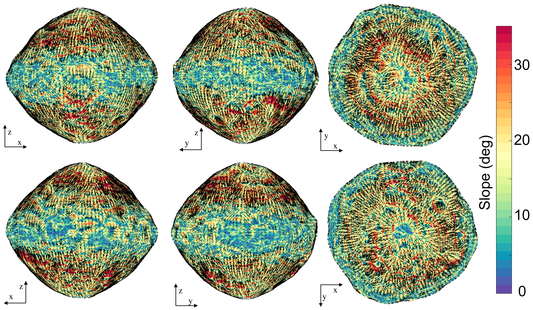
The slope arrows show the direction of downslope motion with length scaled by the local slope angle. The slopes are computed for the 3-m-resolution shape model, as this emphasizes the overall slope trends across the body, whereas higher resolution shape models would reflect the boulder morphology on the surface. The slopes are capped at 35°, with yellow regions going up to 46°.
There are eight synchronous orbits about Bennu, locations where an orbiting body will be stationary in the Bennu fixed frame due to a balance between gravitational and centrifugal forces (Fig. 2). The number of equilibrium points is consistent with the strong degree-4 sectoral coefficients of the shape that create a “square” equatorial profile [3]. These orbits lie less than 50 m from the Bennu surface, and their presence and stability properties control the dynamics of any particles lofted from the equatorial region at low speeds. For the current model, seven of these equilibria are unstable, and one is stable – although its stability is very sensitive to small details of the gravity field and shape, and thus its stability determination may change. The presence of the unstable equilibrium points creates a chaotic orbital environment in this region.
Figure 2: Equilibrium points in the Bennu-fixed frame, shown with stable and unstable manifolds emanating from the unstable points, and showing a stable trajectory in the vicinity of the stable equilibrium point.
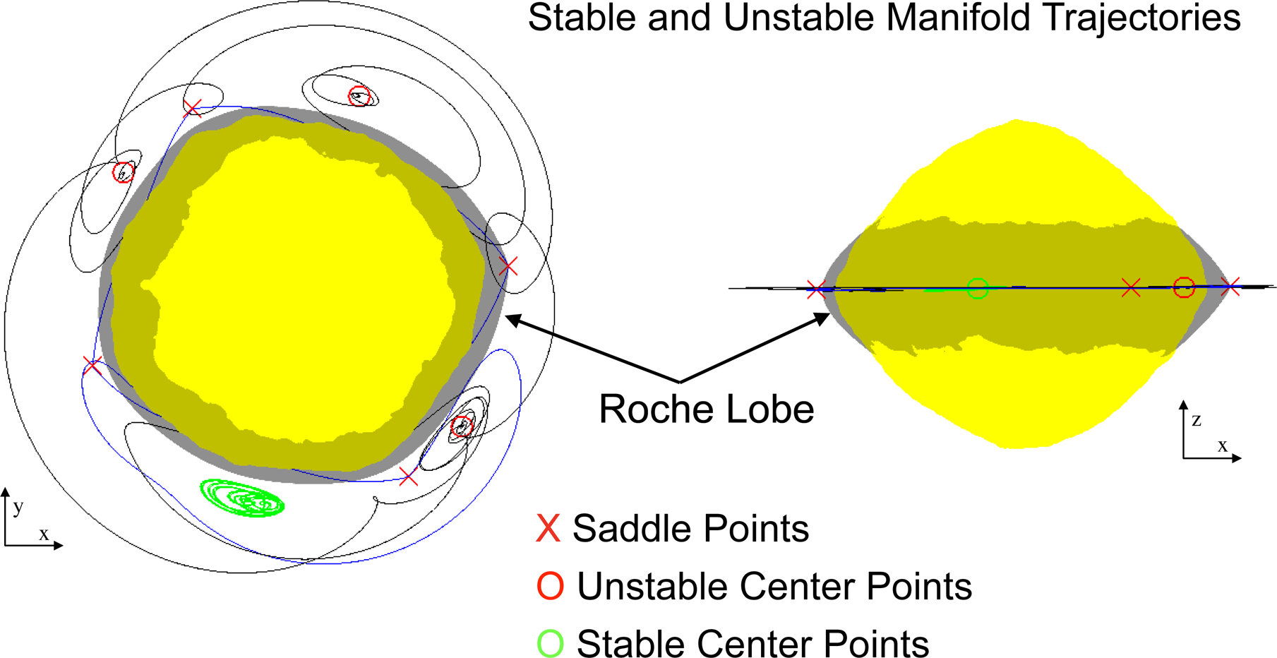
The manifolds control dynamical motion close to Bennu’s surface and create a chaotic orbit environment that would redistribute lofted material. The rotational Roche lobe is also shown as the dark surface that emanates from the minimum-energy equilibrium point and intersects with the Bennu surface, shown with a pole-on view and a side-view.
The geopotential also defines what we term Bennu’s “rotational Roche lobe,” defined as the spatial surface where the geopotential has the same value as the equilibrium point with minimum energy [8]. The lobe is thus the minimum-energy surface that separates Bennu from space and intersects Bennu’s shape at average latitudes of −22.4° and 23.4°. The surface region between these latitudes lies within the lobe, while the true intersection point varies by a few degrees in latitude as a function of longitude, driven by the asteroid’s shape (Fig. 3). Within this latitude band, any particles lofted with an energy less than the rotational Roche lobe energy, which corresponds to speeds < 4 cm/s, are trapped within the lobe; they cannot escape from Bennu and will eventually reimpact the surface between these latitudes (Supplementary Fig. 4). Conversely, speeds that place a particle directly on an escape trajectory range from more than 20 cm/s in the polar regions down to 10 cm/s in the equatorial region, and are highly dependent on surface orientation (Supplementary Fig. 4). Between these speeds, the outcome can be either reimpact, escape, or capture into a longer-term stable orbit that could persist for days to years. The range of orbits that can remain stable about Bennu depends on particle size (which controls the strength of solar radiation pressure) and ranges from centimeter-sized particles close to the surface and in near-polar orbits, to larger bodies in equatorial orbits out to its Hill sphere, which extends to 31 km [13].
Figure 3: Surface slope distributions on Bennu in relation to the rotational Roche lobe.
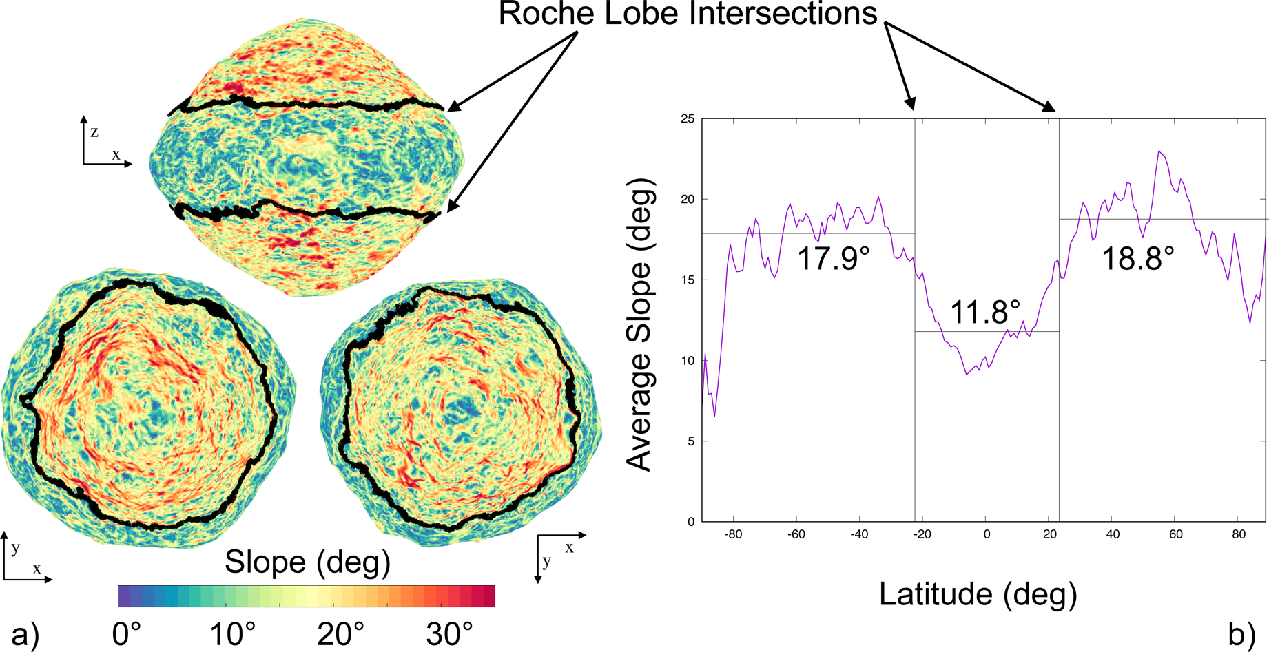
a, Slope distribution for a 3-m-resolution shape model of Bennu shown with the rotational Roche lobe intersection with the surface, marked with the thick black line. The slope transition is seen to closely follow the lobe intersection region. b, Longitudinally averaged slope as a function of latitude, showing the average slopes within and outside of the lobe. The averaging is over 1-degree-latitude bins, and thus at the average lobe transition latitude will capture some regions on the other side of the lobe. If the averaging is performed exclusively within the lobe the average slope decreases to 11.7°, and the overall average slope outside of the lobe is 18.4°.
Surface slope distribution and the rotational Roche lobe
Surface slopes determined for Bennu are highly sensitive to the resolution of the shape model used for analysis, as higher resolution models start to capture the steep slopes of surface boulders. However, the overall global structure of slope distributions on Bennu are seen to have the same pattern independent of shape resolution. For a 3-m-resolution shape model, the globally averaged slopes are 15.4° (Fig. 1). The slope distribution shows a clear transition that occurs at the rotational Roche lobe (Fig. 3), with the surface within the lobe being more energetically relaxed than the surface outside of the lobe. Within the rotational Roche lobe the surface has an average slope of 11.8°, whereas latitudes outside of the lobe have an average slope of 17.9° in the southern (–Z) and 18.8° in the northern (+Z) hemisphere. The dynamics associated with the rotational Roche lobe may have contributed to the relaxed slope within the lobe. For example, if there were a cloud of particles orbiting about Bennu’s equator, some fraction of those could be trapped within the lobe and would redistribute themselves in this region, whereas those with greater energy or located outside of the lobe would preferentially escape or enter longer-term stable orbits. Also, particles, grains and boulders that migrate downslope from the higher latitudes (where they otherwise have sufficient energy to enter orbit) become trapped within the lobe once they enter this region.
The latitudes of the lobe intersection are tied to the current spin rate of the asteroid. This is significant given the measured spin rate acceleration described in Nolan et al. [14] and updated in Hergenrother et al. [15]. Thus a slower rotation rate in the past would lead to the lobe having higher-latitude intersections. The surface relaxation process may therefore be occurring concurrently with Bennu’s changing spin rate. If this measured acceleration is due to the YORP (Yarkovsky–O’Keefe–Radzievskii–Paddack) effect, defined as small torques causing an asteroid’s spin rate to change and arising from photons being scattered from asymmetries in its shape, it will double Bennu’s spin rate in 1.5 million years (which defines Bennu’s YORP timescale). If the observed increase in rotation rate persisted linearly back in time, the asteroid was spinning at a 5-hour period 450,000 years ago, putting the lobe intersection at ±49°, whereas 750,000 years ago the asteroid was spinning at an 8.6-hour period, putting the entire surface within the lobe.
This observation of a slope transition at the lobe boundary indicates that the energetic trapping defined by the rotational Roche lobe may play a role in controlling the shape and topography of the surface. This is important given that all fast-spinning, top-shaped asteroids will have similar intersections of their rotational Roche lobes in their mid-latitudes. Such asteroids are commonly found within the near-Earth asteroid population, and are the most frequently found morphology for binary asteroid primaries (which constitute about 15% of the near-Earth asteroid population) [16]. Binary primaries actually spin even faster than Bennu in general, implying that they have an even narrower lobe about the equator, which increases the likelihood that material can enter orbit and leave the lobe, potentially forming binaries [17, 18, 19]. Thus, our observation that the surface morphology follows the rotational Roche lobe may also be an important clue linking binary formation to fast-spinning, top-shaped asteroids.
Constraints on the origin of Bennu’s shape
Several formation mechanisms have been proposed for top–shaped asteroids, and the OSIRIS-REx mission provides an opportunity to probe and test these hypotheses. A direct interpretation of the surface age of Bennu from crater density indicates an age of 100 million to 1 billion years [11]. Thus, it is possible that the asteroid’s distinctive shape was formed either during accretion [20,21] or during a reshaping event earlier in its history. However, a primordial shape is inconsistent with the current slope transition at the lobe intersection and the measured acceleration in its rotation period, which suggests that Bennu’s surface changes in conjunction with its rotation rate.
An early or initial shape formation could imply that Bennu has avoided going through multiple YORP cycles – periods of more rapid rotation due to YORP – which then lead to shape deformations and periods of slower rotation, with the sequence occurring repetitively every few YORP timescales of 1.5 million years [22,23]. The avoidance of such YORP cycles could be explained if Bennu were trapped in a YORP equilibrium for an extended period of time in the main belt, in which there would be no change in its rotation state and hence shape [24]. Under this scenario, the asteroid may have been disturbed only recently from this equilibrium, perhaps by its passage into the inner Solar System [23]. Alternatively, it could imply that our understanding of how rubble-pile bodies respond to periods of rapid rotation is incomplete.
To study the implications of YORP evolution on Bennu’s shape, we performed a stress analysis for faster spin rates [25]. Figure 4 shows the minimum cohesive strength needed to keep the body from undergoing plastic deformation and the regions where it would first fail in this way at different spin rates. At its current spin period and up to 3.7 hours, a cohesive strength on the order of 0.1 Pa or more is needed to stabilize the surface against mass wasting. At spin periods of 3.6 hours and faster, a strength of 1 Pa or more is needed to stabilize the interior. For context, recall that the weight of a 1 m boulder on Bennu’s equator would exert a pressure of 0.1 Pa. A complementary analysis of surface slopes (Fig. 4) shows that at spin periods below 3.6 hours, over half of Bennu’s surface is at or exceeds an angle of repose of 30° and would definitively fail via mass wasting if it were a cohesionless regolith.
Figure 4: Failure patterns as a function of Bennu spin rates.
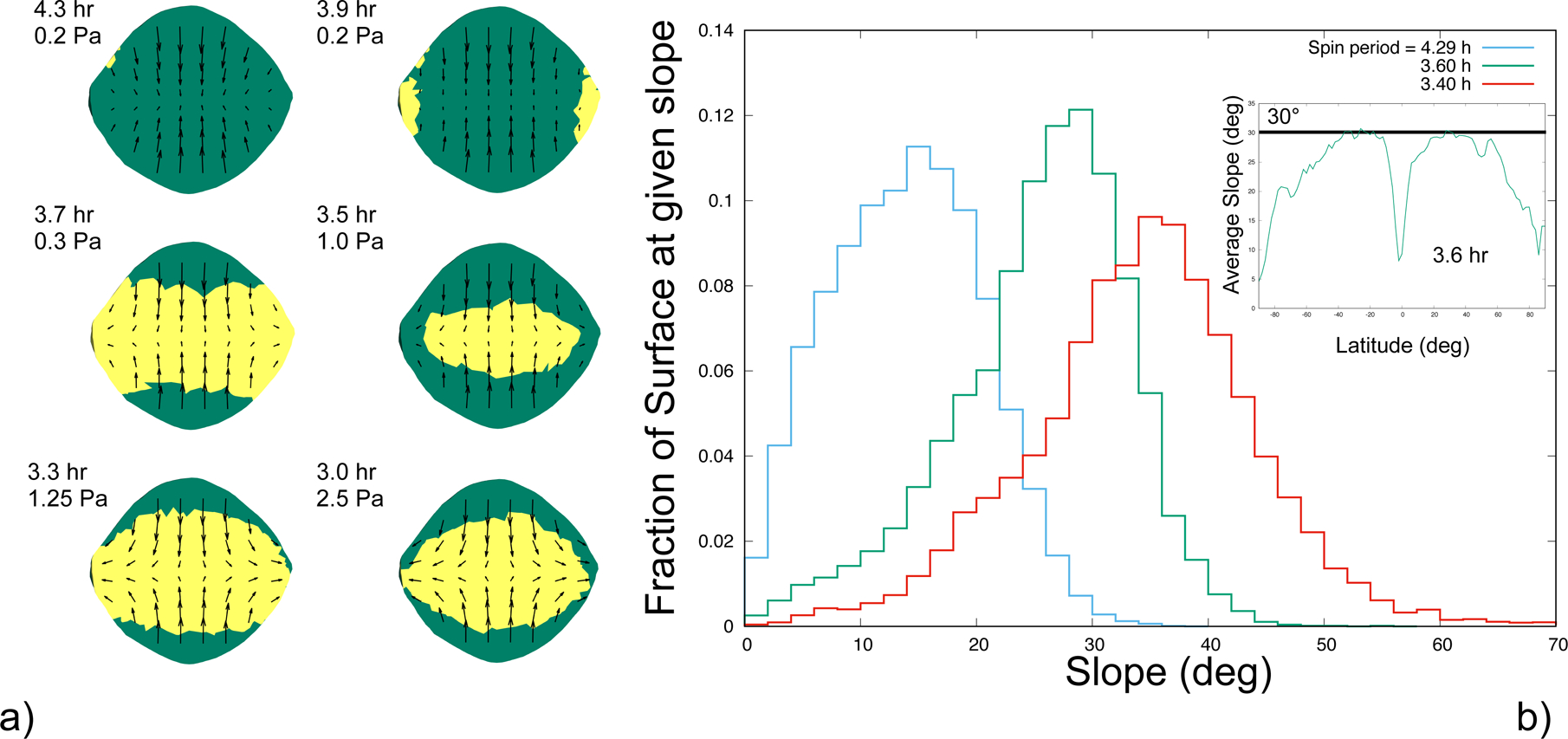
a, Shape stability maps showing regions of elastic deformation (green) and plastic deformation (yellow) with arrows showing the direction of deformation at different spin periods and strengths. Under a uniform density and strength distribution assumption, Bennu requires less than 0.3 Pa of strength to retain surface stability up to a spin period of 3.7 hours. At faster spin periods, failure occurs across the interior of the body, and Bennu requires a strength of at least 1 Pa to maintain its current shape. b, The surface slope distribution has its accumulation point at around 3.6 hours, beyond which the majority of the surface is beyond the usual 30° angle of repose for cohesionless material [28]. The inset shows the average slope as a function of latitude at a 3.6-hour spin period.
If Bennu acquired its distinctive shape after its initial formation, three main mechanisms have been proposed [8]: formation by downslope migration of material from mid-latitudes to the equatorial region [26, 27, 28]; failure and collapse of the interior of the body, deforming the surface of the asteroid [25, 29, 30]; or the tidal disruption of a natural satellite that fell back onto the asteroid surface [31, 32]. The conformity of the slope change with the Roche lobe would be consistent with this last scenario, as such an event would distribute a large amount of material across the equator at low speeds, which would preferentially settle within the lobe. As this would be a one-time event, it seems inconsistent with the age of the surface and the current acceleration of the spin rate, however.
An interior failure could have occurred in the past, and granular mechanics simulations show that if the interior had bulged outwards, surface structures could have been maintained without deformation (methods), implying that even a more recent interior failure mode such as this could be feasible and consistent with an old surface. This failure mode would predict a less dense interior as compared to our measured bulk density [25,30], and would correspond to gravity coefficients that are larger than the shape-based constant density gravity coefficients. If, instead, the interior strength were sufficient to prohibit that failure mode, then the mantle of surface material would fail at a fast spin rate [28]. Comparison of the surface slope distribution at past plausible spin rates shows that the current surface is consistent with failure at a spin rate of 3.6 hours (Fig. 4) and yields a shape that is consistent with this failure mode (Fig. 5) [27, 19]. These findings support the possibility of a denser core, with corresponding lower values of gravity coefficients.
Figure 5: The averaged Bennu shape shows global characteristics associated with a landslide failure.
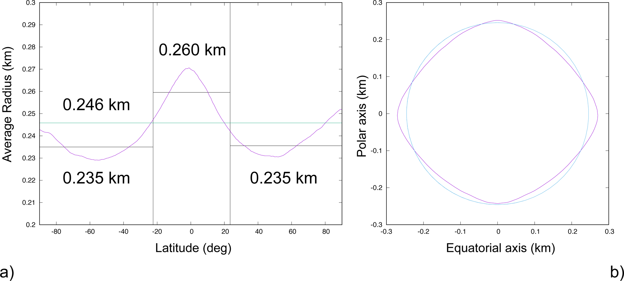
a, The longitudinally averaged Bennu radius as a function of latitude, shown in purple. The green line is the globally averaged radius and the black lines are the averages inside and outside of the lobe. b, Bennu’s shape profile (purple line) compared with its average radius (blue). The smaller radius at mid-latitudes, pole radii close to the mean radius, and exuded equator constitute a predicted profile for a global surface landslide [19].
Density heterogeneity within Bennu
These hypotheses show the importance of constraining the internal density distribution of Bennu. We can begin to explore this by analyzing Bennu’s shape model, which is constructed such that its origin is at the center of mass and that it spins about its maximum moment of inertia. Under a constant density assumption, the offset between the center of figure and center of mass is [1.4, −0.5, −0.15] m in the Bennu-fixed frame. The corresponding products of inertia are Izx = − 46.70 m2 and Izy = 11.39 m2, as compared to its predicted maximum moment of inertia Izz = 26,780 m2 [3,33]. These measurements correspond to a ~0.1% shift in the center of mass and a ~0.1° offset of the principal axis with respect to a constant density shape, and they indicate heterogeneity in the mass distribution. To account for this heterogeneity with a simple (but non-unique) model consistent with surface observations and Bennu’s rubble-pile structure, we assume that Bennu contains two spherical boulders with a particle density twice the measured bulk density (assuming a 50% porosity) and diameters of 80 m (less than the largest boulder outcrop size seen on Bennu [7,11]). These objects would constitute almost 1% of the total mass and would have a density of 2360 kg/m3 with the bulk density of the remaining body at 1180 kg/m3. To match the observed asymmetry, both boulders must be displaced in the −x direction, with one of them having its largest extent at the surface, and with both bodies displaced in opposite directions about the equatorial plane with a total separation between them of 200 m (methods, Supplementary Fig. 5). Although this solution is not unique, it establishes that the offsets can be explained in a plausible model.
OSIRIS-REx’s future low orbits about Bennu will refine our understanding of the surface and enable us to estimate higher-order gravity field coefficients. These measurements will increase the resolution at which we can detect and constrain Bennu’s internal heterogeneities and will provide direct evidence of how the mass is distributed within the body. This, in turn, will enable us to evaluate the competing theories for how its shape formed, or may suggest new alternative models that must be considered. They will also shed additional light on the connections between Bennu’s apparent migration of its surface slopes, pathways to the formation of top-shaped asteroids and ultimately provide insights into binary formation.
Methods
Shape Model:
The results in this paper were computed using the Version 14 shape model, as defined in Barnouin et al. [3].
Mass measurement and estimation:
The Bennu mass measurement experiment carried out by the OSIRIS-REx mission involved several teams each using unique combinations of software tools and data processing techniques. The Radio Science teams were based at the University of Colorado in the Colorado Center for Astrodynamics Research (CU) and at the Jet Propulsion Laboratory (JPL). The navigation and flight dynamics teams were represented by KinetX Corporation with a team in residence at Lockheed Martin’s Waterton Campus in Denver and a team at Goddard Space Flight Center (GSFC). The mass estimates and other fitting data from each team were compared against each other and found to converge to the same mass value within the expected errors. The specific value quoted in the paper is from the CU estimate, however all other estimates agreed to this value within the quoted error estimates as of early January.
The OSIRIS-REx spacecraft began the Approach phase towards asteroid Bennu on 17 August 2018. During Approach the spacecraft performed six maneuvers to decelerate the spacecraft with respect to Bennu and place it at the Preliminary Survey starting location on 3 December 2018. Preliminary Survey consisted of five flybys—three over the north pole, one over the equator, and one over the south pole—and two transition legs. Each flyby started approximately 18.5 km from Bennu, took 48 hours to complete, and achieved a closest approach of 7.5 km at the 24 hour mark. The polar flybys were along the terminator and the equatorial flyby was on the sunlit side. All flyby and transition arcs were joined by maneuvers that varied between 20 and 40 cm/s.
Images taken by spacecraft cameras (PolyCam, MapCam, NavCam1) [34] were used to generate center-finding optical navigation data [35]. Optical navigation images were taken between 3 and 7 times per week during Approach and every 2 hours during Preliminary Survey. These data, along with X-Band Two-way Doppler, Two-way Range and Delta-Differential One-way Range (Delta-DOR) from the Deep Space Network (DSN), were used to determine both the spacecraft trajectory and Bennu’s ephemeris.
Solution methods summaries
Radio Science Team:
The CU Radio Science orbit determination solutions were computed using JPL’s Mission Analysis, Operations and Navigation Toolkit Environment (MONTE) [36]. Two-way Doppler and Two-way Range were weighted per-pass and per antenna at twice their observed noises to prevent over-fitting to imperfectly calibrated data. Per-pass range biases were estimated with an a priori uncertainty of 10 Range Units (RU), where 7.022 RU = 1 meter. DDOR was weighted at 0.06 nanoseconds, the recommended value provided by the DSN. Optical center-finding sample and line were weighted at 0.5 pixels on Approach and de-weighted to 2.0 pixels during Preliminary Survey to account for the increase in Bennu’s apparent diameter.
Non-gravitational perturbations to the spacecraft trajectory were characterized prior to the start of Preliminary Survey in order to minimize aliasing between solar pressure, stochastic accelerations, and GM. Area scale factors for each of the sun-ward facing plates were estimated on Approach to account for solar pressure and thermal radiation mis-modeling. The plate areas were then held fixed during Preliminary Survey and a single solar pressure scale factor was estimated. Stochastic accelerations were estimated in 12-hour batches with an a priori uncertainty of 5 × 10⁻¹³ km/s2. Due to the regular cadence of the flyby/maneuver cycle the stochastic accelerations were correlated exponentially with a 3-day time constant after M1P to prevent interplay with the GM and the maneuvers. In addition to these, parameters estimated in the solution included the spacecraft state at epoch, the Bennu ephemeris, momentum wheel desaturation maneuvers, targeting maneuver thrust and pointing, per-pass range biases and the Bennu gravitational parameter.
The final reconstructed uncertainty for the spacecraft’s Bennu-relative state averaged approximately 5 meters in position and 0.2 mm/s in velocity for each axis, 3-sigma. Solutions were generated for various data weights, stochastic uncertainties/batch lengths/correlation times. It was noted that the GM trended lower with tighter radio weights and/or larger stochastic uncertainty, however all solutions produced both trajectories and GM’s consistent to the 1-sigma level.
The JPL estimation setup is similar, and more details can be found in ref. [37].
KinetX:
The OSIRIS-REx navigation team’s best-estimate of the Bennu GM following the Preliminary Survey phase is 4.89 ± 0.006 (1-sigma) m3/s2.
Extensive work went into modeling the spacecraft down to the acceleration level of 1.0 × 10⁻¹³ km/s2 level going into the first North Pole Flyby of Bennu. Throughout cruise, the approach taken by the OSIRIS-REx Orbit Determination team was to model every deterministic acceleration using physics based models. No non-physical scaling of the Solar Radiation Pressure was used. A 10 plate box-wing model was used for the spacecraft with measured areas obtained from pre-launch 3D models. Documentation from Lockheed Martin and closeout photos of the spacecraft in flight configuration were used to determine the material covering of each surface as well as the specular and diffuse reflectivity coefficients. Coordination with the LM thermal team provided a detailed thermal re-radiation model of the spacecraft surfaces for the 10 plate model as well as the addition of the radiators located on the −Z deck of the spacecraft. The model developed with the LM thermal team spanned predicted temperatures for each panel over various solar distances and off sun angles. This approach was taken due to the fact that the passive Lambertian assumption for diffuse radiation of the surfaces did not accurately model the thermal re-radiation effects as seen from an active spacecraft. This thermal re-radiation model along with the estimation of the specular and diffuse re-radiation coefficients of the 10 plate SRP model produced a model that matched the pre-launch surface properties and acceleration accuracies to less than 0.5% of the SRP acceleration. This model continuously predicted the approach trajectory to less than 1-sigma of the predicted trajectory uncertainties with random fluctuations in estimated stochastic accelerations on the order of 0.5 × 10⁻¹³ km/s2 1-sigma. These additional estimated accelerations were correlated with increased spacecraft activities and off-nominal attitude orientations not seen during cruise.
In addition to the SRP and thermal modeling, the OD team was able to estimate discrepancies between the internal electronic path delays provided pre-launch and what was continuously seen in flight. Coordination with the Telecom team provided corrections to the radiometric data based on the location of the antenna phase-center offsets. All antenna phase-center offsets were estimated in flight during slewing activities to confirm the pre-launch provided locations. All ground station and EOP corrections were updated to coincide with those recommended by the IERS 2010 conventions. Ground station locations are corrected based on solid tides, pole tides, ocean tides, polar motion and continental drift. An acceleration correction due to the electromagnetic radiation pressure of the HGA and LGA antennas as well as OLA was modeled throughout Approach.
The OD team estimated the spacecraft state, finite maneuvers, desaturation maneuvers, per-pass range biases, Bennu Ephemeris, stochastic un-modeled accelerations, and SRP scaling. Radiometric data of 2-Way Range and Doppler, DDOR and Optical Images using Gaussian 2D fitting, phase corrections and cross-correlation limb fitting techniques were the primary source of observables processed. Prior to the initial Preliminary North Pole flyby, the navigation team trended the estimated solution parameters. No stochastic accelerations were estimated after the first Preliminary Survey. This was done to make sure no soak up parameters masked the gravity signal during the flybys.
GSFC:
Members of the Flight Dynamics Team located at NASA Goddard Space Flight Center (GSFC) generated an independent spacecraft trajectory solution and Bennu GM estimate at the end of the Preliminary Survey phase. This solution utilized the GEODYN orbit determination and geophysical parameter estimation software package, also developed and maintained at GSFC [38].
The GSFC solution included DSN radiometric (sequential range, Doppler, and DDOR) and center-finding optical navigation (OpNav) measurement types. The center-finding measurements were constructed by processing MapCam and NavCam images in the Goddard Image Analysis and Navigation Tool (GIANT) [39]. GIANT uses stars in adjoining long exposure images to provide precise absolute (inertial) pointing information interpolated to the epoch of short exposure images containing Bennu’s full extent. The center of Bennu in the image is determined precisely through 2D cross-correlation of Bennu’s illuminated shape in the image along with a rendered template of the estimated shape model. The model used for Preliminary Survey was constructed by OSIRIS-REx Altimetry Working Group (AltWG) member Dr. Robert Gaskell using stereophotoclinometry [40] based on Approach PolyCam imagery and delivered on 27 November 2018. The measurement data weights for DSN Sequential Range were 21 Range Units, for DSN 2-Way Doppler were 5.5 mHz, for DSN Delta-Differenced One-Way Range were 0.06 ns, and for OpNAV Center-finding were 1 pixel. Direct altimetry data from the OSIRIS-REx Laser Altimeter (OLA) [41] taken during four of the Preliminary Survey flybys were processed along with the other measurement data types but not included in the final solution.
The final Preliminary Survey arc started on 3 December and ended on 24 December. A summary of the estimated parameter list included the spacecraft and asteroid epoch states, the Bennu gravitational parameter, spacecraft maneuvers and momentum wheel desaturations, 3-axis stochastic accelerations with a priori uncertainties of 1 nm/s2 and per pass range biases with 2 meter apriori uncertainty. Force modeling included point mass gravitation (Sun, 8 Planets + Pluto), Bennu non-spherical gravity (15×15 assuming uniform density), 11-plate solar radiation pressure (SRP), spacecraft thermal radiation, and stochastic accelerations. Temperatures for the thermal radiation model were provided by the spacecraft team at Lockheed Martin as originally requested by KinetX Aerospace. Reconstructed spacecraft attitude and panel orientation information was also provided by the spacecraft team. In addition to the integration and estimation of the OSIRIS-REx trajectory, the orbit of Bennu itself is concurrently integrated and estimated as well. The a priori initial state and fully-correlated covariance for Bennu was obtained from the OSIRIS-REx Radio Science Working Group and the JPL Group (Solution #103, Delivered 8 November) [37]. All spacecraft maneuvers (M2P through M1A) were modeled as impulsive V’s with a priori values and uncertainties provided by the spacecraft team via Maneuver Implementation Files (MIFs). Initial values for spacecraft momentum desaturations were derived from the number of pulse counts provided in the Small Forces File (SFF) and trending data since launch.
Density heterogeneity constraint computations
To develop a simple yet physically feasible model to fit the non-zero center of mass and product of inertia information with a density distribution we implement the following algorithm and approach.
Density:
Assuming a 50% macroporosity we consider mass contributions to be twice the bulk density. Note, this is equivalent—but opposite—to introducing zero density voids into the body.
Size:
The largest body observed on Bennu is at most 80 m in diameter (one dimension). Taking this as a limiting value, we choose boulders of 80 m in diameter. Using a smaller size will require the masses to be pushed farther from the center of the asteroid. This sets the masses of the two boulders and yields the following.
The mass fractions of the shape and individual grains are 0.9914 and 0.0043, respectively, and are defined as the mass of the component over the total mass. Bulk densities of the shape and individual grains are 1178 kg/m3 and 2356 kg/m3, respectively.
Constraints:
The center of mass provides three constraints that need to be satisfied by the grain locations, captured in a single vector equation
where the 0 subscript represents the main body, the subscript COF represent center of figure, and the subscripts 1 and 2 represent the two bodies, respectively.
The products of inertia, assuming mass normalized values, provide two additional equations
The system as specified is over constrained, with 6 free variables (position vectors of each body) and 5 constraints. To reduce this we introduce an additional constraint, forcing the boulders to have a fixed relative offset in the z-coordinate:
where ΔZ is a free, dimensionless parameter. If it is greater than −1 the two masses are on the same side of the equator, if −1 then both are zero—meaning that a z component in the center of mass cannot be accommodated, if less than −1 then they are on opposite sides. With this constraint we can then solve for the z-components as
and then solve the resulting linear equations for the x-y components to find:
Finally, to choose the nominal values we vary the parameter ΔZ over the interval (−1.86, −1.96) to find locations that are nominally within Bennu. The value used in the paper is −1.9, which places the outermost of these points deepest within the body, allowing its 40 m radius to just lie at the surface. Supplementary Figure 5 shows this plotted on top of the average radius shape model.
Bennu’s geophysical environment computations and supporting results
The methods and supporting documentation on how the geophysical environment items were computed is summarized and presented in greater detail in ref. [42]. When applied to the current estimate of the Bennu shape, mass and spin state this yields computations of the surface acceleration, the surface geopotential energy, the return speed, the escape speed and the slopes and slope directions. With the exception of the slope, these computations all appear similar to that reported to the pre-arrival model, albeit with definite values now. Thus, these are presented below with some notes. The computation of the lift-off speed applies the formulae defined in citation ref. [12] to a polyhedral surface as outlined in [43].
Equilibrium point computation and characterization
The Bennu equilibrium points are computed following the algorithm in ref. [44] and their stability evaluated as described in ref. [42]. Bennu is found to have 8 synchronous orbits close to its surface. Four of these are hyperbolically unstable saddle points, while the other four are center equilibrium points and can either be stable or unstable. For the current model three of these center equilibria are unstable and one is stable (Fig. 2). The presence of a stable equilibrium point implies that there is a zone about the body where particles, if placed appropriately, can remain in orbit indefinitely about a region in the body-fixed frame. This stable equilibrium point has three distinct oscillation frequencies, two in-plane with periods of 5.8 and 8.6 hours, and one out-of-plane a period of 3.9 hours. The stability of this point is sensitive to the detailed gravity field of the asteroid, and thus may be updated once higher order gravity field coefficients are estimated.
The remaining equilibria are hyperbolically unstable, with characteristic times for the saddle points ranging from 1 to 1.4 hours and 2.6 to 3.4 hours for the unstable center points. All have stable out of plane oscillations with periods around 3.9 hours. We denote the dynamical region in the vicinity of the equator as chaotic based on these stability determinations. This designation is appropriate as the expected presence of heteroclinic tangles associated with these equilibrium points (specifically, associated with manifolds from periodic orbits and quasi-periodic orbits in their vicinity) creates a chaotic orbital environment for any material lifted from the surface at low speeds.
Rotational Roche lobe computation:
The rotational Roche lobe is found by finding the lowest geopotential energy of the eight equilibrium points, which turns out to be the one that lies close to the positive x-axis. Given this Roche lobe energy, we adjust the radii of a chosen shape model until the point reaches this energy value, computed with a relative precision of 10−5. Vertices that are within 1 meter of the surface are considered to be locations where the lobe is intersecting the asteroid surface, and are plotted as black points in Fig. 3. This computation is independent of the slope computations, meaning that transitions seen in the figure are not adjusted in any way, and represent the true variation. To compute the lobe at different spin periods, the entire process is repeated, including finding the new equilibrium points.
Stress and deformation analysis of Bennu
The methodology for computing the stress and failure analysis of Bennu is outlined in ref. [29]. The computations assume a uniform density and strength distribution, and an angle of friction of 35°. The computations were carried out using ANSYS Mechanical APDL (17.0) on the Auburn University Hopper supercomputing system. Additional runs were made that varied the internal density — for both a higher and a lower density — but did not see any substantial deviation in the necessary strengths or spin periods at failure. Future analysis will use more detailed maps of internal density distribution to probe the asteroid failure state due to periods of high rotation.
To probe the effect of an internal deformation on the surface regolith, the granular mechanics model outlined in ref. [18] was applied to a representative longitude lune, starting at a spherical shape and distorting it into an equatorial bulge to mimic the Bennu ridge. For both cohesionless and cohesive grains we did not observe significant distortion of the surface material on the equator, consistent with features on the surface potentially being retained during a period of shape deformation due to internal failure. Distortion of the surface close to the pole however seems to be related to the violence of the reshaping and the strength of the regolith.
To analyze the global shape and trends across the surface, the slope and radius of Bennu was averaged over longitude within latitude bands of 1°. To perform these averages all facets with a centroid within a given latitude interval were identified, and the quantity of interest was multiplied by the differential area of the latitude band (computed at the local radius value) and summed, in effect performing an average across the longitude of the asteroid. This quantity was then divided by the summed total area of these regions, performing an area normalized average of the quantity. The averages were performed across the 3 m resolution shape model, which has about 200,000 facets, providing on average over 1000 facets per latitude bin.
Data Availability
The data that support the plots within this paper and other findings of this study are available from the corresponding author upon reasonable request. Spacecraft tracking data and ancillary files will be available via the Small Bodies Node of the Planetary Data System (PDS) (https://pds-smallbodies.astro.umd.edu/). Data are delivered to the PDS according to the OSIRIS-REx Data Management Plan available in the OSIRIS-REx PDS archive. Higher-level products, e.g., slope maps, will be available in the PDS 1 year after departure from the asteroid.
Supplementary Material
Acknowledgements
This material is based upon work supported by NASA under Contract NNM10AA11C issued through the New Frontiers Program. Work by M.G.D, C.L.J, M.M.A.A. and H.C.M.S. was supported by the Canadian Space Agency. A portion of this work was carried out at the Jet Propulsion Laboratory, California Institute of Technology, under a contract with the National Aeronautics and Space Administration. P.M. acknowledges funding support from the French space agency CNES and from Academies of Excellence: Complex systems and Space, environment, risk, and resilience, part of the IDEX JEDI of the Université Côte d’Azur. B.R. acknowledges support from the Royal Astronomical Society in the form of a research fellowship. P.T. acknowledges support from NASA’s OSIRIS-REx Participating Scientist Program through grant 80NSSC18K0280. M.H. acknowledges support from the Department of Aerospace Engineering at Auburn University.
References
- [1].McMahon JW et al. , The OSIRIS-REx radio science experiment at Bennu, Space Sci. Rev 214, 43 (2018). [Google Scholar]
- [2].Williams B et al. OSIRIS-REx flight dynamics and navigation design. Space Sci. Rev 214, 69 (2018). [Google Scholar]
- [3].Barnouin OS et al. Submitted to Nat. Geosci. (this package). [Google Scholar]
- [4].Watanabe S et al. Hayabusa2 observations of the top-shaped carbonaceous asteroid 162173 Ryugu. Submitted to Science. [DOI] [PubMed] [Google Scholar]
- [5].Chesley SR, Farnocchia D, Nolan MC, et al. Orbit and bulk density of the OSIRIS-REx target asteroid (101955) Bennu. Icarus 235, 5–22 (2014). [Google Scholar]
- [6].Rozitis B and Green S The influence of rough surface thermal-infrared beaming on the Yarkovsky and YORP effects. Mon. Not. R. Astron. Soc 423, 367–388 (2012). [Google Scholar]
- [7].DellaGiustina D, Emery J, et al. Submitted to Nat. Astron. (this package). [Google Scholar]
- [8].Scheeres DJ et al. The geophysical environment of Bennu. Icarus 276, 116–140 (2016). [Google Scholar]
- [9].Murdoch N, Sanchez P, Schwartz SR, Miyamoto H in Asteroids IV (ed. Michel P, DeMeo FE, Bottke WF), pp. 767–792 (Univ. of Arizona Press, Tucson, AZ, 2015). [Google Scholar]
- [10].Scheeres DJ, Hartzell CM, Sánchez P, Swift M Scaling forces to asteroid surfaces: The role of cohesion. Icarus 210: 968–984 (2010). [Google Scholar]
- [11].Walsh KJ et al. Submitted to Nat Geosci. (this package). [Google Scholar]
- [12].Van wal S, Scheeres DJ The lift-off velocity on the surface of an arbitrary body. Celest. Mech. Dynam. Astron 125, 1–31 (2016). [Google Scholar]
- [13].Rieger SM, Barbee B, Scheeres DJ Orbital Stability Regions for Hypothetical Natural Satellites of 101955 Bennu (1999 RQ36). Journal of Spacecraft and Rockets, in press (June/2018). [Google Scholar]
- [14].Nolan MC et al. Detection of Rotational Acceleration of Bennu using HST Lightcurve Observations. Geophysical Research Letters in press (2019). [Google Scholar]
- [15].Hergenrother C et al. Submitted to Nat. Commun. (this package). [Google Scholar]
- [16].Pravec P et al. , Binary asteroid population. 3. secondary rotations and elongations. Icarus 267, 267–295 (2016) [Google Scholar]
- [17].Walsh KJ, Richardson DC, Michel P Spin-up of rubble-pile asteroids: disruption, satellite formation, and equilibrium shapes. Icarus 220, 514–529 (2012). [Google Scholar]
- [18].Tardivel S, Sánchez P, Scheeres DJ Equatorial cavities on asteroids, an evidence of fission events. Icarus 304, 192–208 (2018). [Google Scholar]
- [19].Scheeres DJ Landslides and mass shedding on spinning spheroidal asteroids. Icarus 247, 1–17 (2015). [Google Scholar]
- [20].Sánchez DP, Scheeres DJ The role of angular momentum on accreting rubble pile shapes. 49th LPSC, Abstract 1196 (2018). [Google Scholar]
- [21].Michel P et al. Disruption and Reaccumulation as the Origin of the Ryugu and Bennu Top Shapes? AGU Fall Meeting 2018, Abstract P33C–3850 (2018). [Google Scholar]
- [22].Statler TS Extreme sensitivity of the YORP effect to small-scale topography. Icarus 202, 502–513 (2009). [Google Scholar]
- [23].Bottke WF et al. In search of the source of asteroid (101955) Bennu: Applications of the stochastic YORP model. Icarus 247, 191–217 (2015). [Google Scholar]
- [24].Golubov O, Scheeres DJ Systematic structure and sinks in the YORP effect. Astrophys. J, in press. [Google Scholar]
- [25].Hirabayashi M, Scheeres DJ Stress and failure analysis of rapidly rotating asteroid (29075) 1950 DA. Astrophys. J. Lett 798, L8 (2015). [Google Scholar]
- [26].Minton DA The topographic limits of gravitationally bound, rotating sand piles. Icarus 195, 698–704 (2008). [Google Scholar]
- [27].Harris AW, Fahnestock EG, Pravec P On the shapes and spins of ‘rubble pile’ asteroids. Icarus 199, 310–318 (2009). [Google Scholar]
- [28].Hirabayashi M, Sánchez P, Scheeres DJ Internal structure of asteroids having surface shedding due to rotational instability. Astrophys. J 808, 63 (2015). [Google Scholar]
- [29].Hirabayashi M, Scheeres DJ Rotationally induced failure of irregularly shaped asteroids. Icarus 317, 354–364 (2019). [Google Scholar]
- [30].Sánchez P, Scheeres DJ Rotational evolution of self-gravitating aggregates with cores of variable strength. Planetary and Space Science 157:39–47. (2018) DOI: 10.1016/j.pss.2018.04.001 [DOI] [Google Scholar]
- [31].Scheeres DJ et al. Dynamical configuration of binary near-earth asteroid (66391) 1999 KW4. Science 314, 1280–1283 (2006). [DOI] [PubMed] [Google Scholar]
- [32].Jacobson SA, Scheeres DJ Dynamics of rotationally fissioned asteroids: Source of observed small asteroid systems. Icarus 214, 161–178 (2011). [Google Scholar]
- [33].Lauretta DS, DellaGiustina D, et al. Submitted to Nature (this package). [Google Scholar]
- [34].Rizk B et al. OCAMS: The OSIRIS-REx Camera Suite. Space Sci. Rev 214, 26 (2018). [DOI] [PMC free article] [PubMed] [Google Scholar]
- [35].Pelgrift JY et al. In-flight calibration of the OSIRIS-REx optical navigation imagers 1st Annual RPI Workshop on Image-Based Modeling and Navigation for Space Applications, Troy, NY, 2018. [Google Scholar]
- [36].Evans S, Taber W, Drain T et al. MONTE: the next generation of mission design and navigation software. CEAS Space J 10: 79 (2018). 10.1007/s12567-017-0171-7 [DOI] [Google Scholar]
- [37].Farnocchia D et al. “Asteroid 101955 Bennu Ephemeris Delivery, JPL Solution 103,” JPL IOM 392R-18–005. 16 November 2018. [Google Scholar]
- [38].Pavlis DE, Wimert J, McCarthy JJ GEODYN II Systems Description, Vols. 1–5 (Contract. Rep., SGT Inc., Greenbelt, MD, 2014). [Google Scholar]
- [39].Wright C, Liounis A, Ashman B Optical navigation algorithm performance 1st Annual RPI Workshop on Image-Based Modeling and Navigation for Space Applications, Troy, NY, 2018. [Google Scholar]
- [40].Gaskell RW Automated landmark identification for spacecraft navigation AAS/AIAA Astrodynamics Specialists Conference, Quebec City, Canada, 2001. AAS Paper; 01–422. [Google Scholar]
- [41].Daly M et al. The OSIRIS-REx Laser Altimeter (OLA) investigation and instrument. Space Sci. Rev 212, 899–924 (2017). [Google Scholar]
- [42].Scheeres DJ Orbital Motion in Strongly Perturbed Environments: Applications to Asteroid, Comet and Planetary Satellite Orbiters (Springer-Praxis Books in Astronautical Engineering, Springer, 2012). [Google Scholar]
- [43].Van wal S, Scheeres DJ The Lift-Off Velocity on Solar System Small Bodies. Journal of Guidance, Control, and Dynamics 40(8): 1990–2005 (2017). 10.2514/1.G002337 [DOI] [Google Scholar]
- [44].Tardivel S, Scheeres DJ Dynamical structures for the study of irregular gravity fields. 2017 AAS/AIAA Space Flight Mechanics Meeting, San Antonio, TX, 5 to 9 February 2017. AAS Paper; 17–258. [Google Scholar]
Associated Data
This section collects any data citations, data availability statements, or supplementary materials included in this article.
Supplementary Materials
Data Availability Statement
The data that support the plots within this paper and other findings of this study are available from the corresponding author upon reasonable request. Spacecraft tracking data and ancillary files will be available via the Small Bodies Node of the Planetary Data System (PDS) (https://pds-smallbodies.astro.umd.edu/). Data are delivered to the PDS according to the OSIRIS-REx Data Management Plan available in the OSIRIS-REx PDS archive. Higher-level products, e.g., slope maps, will be available in the PDS 1 year after departure from the asteroid.