

Abstract
Several breakthrough applications in biomedical imaging have been reported in the recent years using advanced photoacoustic microscopy imaging systems. While two photon and other optical microscopy systems have recently emerged in portable and wearable form, there is much less work reported on the portable and wearable photoacoustic microscopy (PAM) systems. Working towards this goal, we report our studies on a low-cost and portable photoacoustic microscopy system that uses a custom fabricated 2.5 mm diameter ring ultrasound transducer integrated with a fiber-coupled laser diode. The ultrasound transducer is centered at 17.25 MHz, and shows ~ 45% and ~ 100% fractional bandwidths for ultrasound pulse-echo and photoacoustic A-line signals respectively. To achieve overall system portability, besides the imaging head, other backend imaging system components need to be readily portable as well. In this direction, we have studied the potential use of compact pre-amplifiers, scanning stages and microcontroller based data acquisition and reconstruction for photoacoustic imaging. The portable PAM system is validated by imaging phantoms embedded with light absorbing targets. Future directions that will likely help achieve a completely portable and wearable photoacoustic microscopy system are discussed.
Keywords: Photoacoustic imaging, Ring ultrasound transducer, Microscopy, PAM, Wearable
I. Introduction
Photoacoustic microscopy (PAM) imaging has undergone tremendous advancements and attracted several biomedical applications since its first demonstration for in vivo tissue imaging in 2005 [1], [2]. PAM relies on the photoacoustic effect—that is the generation of ultrasonic pressure by light absorbing molecules due to thermoelastic expansion upon illumination with pulsed light [3]. Photoacoustic spectroscopy allows mapping of a wide variety of endogenous molecules (e.g., hemoglobin, melanin, DNA, RNA, lipids, and water) and exogenous contrast agents (e.g., small molecules and nanoparticles) with scalable spatial and temporal resolutions and penetration depths [4]–[10]. For example, PAM can provide label-free high-contrast images of vascular morphology, associated oxygen saturation, total hemoglobin concentration, and blood flow from a few mm deep inside the tissue by exploiting the differential absorption spectra of oxy- and deoxy- forms of hemoglobin [11]. Such rich vascular information obtained from PAM has several applications in studying cancer, cardiovascular and neurological diseases [12]–[14].
To date, many technological advances in PAM are focused on improving the speed, resolution, and contrast, including the development of multi-focal systems with scalable penetration depths and resolutions within one setup [15]–[17]. However, most PAM systems are limited to table-top forms as they use expensive and bulky lasers, ultrasound transducers, and complex geometries for combining the ultrasound and the optical components for confocal beam focusing (Fig. 1). Bulky XYZ translational stages are often used in combination with MEMS mirrors for light beam steering, and the subsequent ultrasound output generated by tissue (photoacoustic signal) is acquired using high-cost data acquisition cards for image reconstruction [18], [19]. While conventional optical microscopy systems have undergone a revolution in terms of their portability and use in wearable form [20], [21], there is much less work reported in this direction for PAM. For example, a wearable PAM is desired for pre-clinical neurological studies of freely behaving mice [22] as well as certain clinical applications of imaging/monitoring of human skin cancer or vascular activity for a long period of time. Therefore, there is a need to further advance and scale the PAM technology to a completely portable and/or wearable form for the above point-of-care applications including the deployment of the technology in resource-poor settings. In this paper, we report our initial efforts towards realizing a portable photoacoustic microscope using low-cost and lightweight components and discuss future directions that likely will help achieve an ultraportable and wearable photoacoustic microscope.
Fig. 1.

Optical and acoustic beam arrangements for typical photoacoustic microscopy (PAM) systems: (a) Transmission mode PAM architecture requires access from both sides of the sample and hence it is limited to very thin tissue samples. (b) Two-prism combiner approach for optical and acoustic resolution PAM (c) an axicon and condensing mirror arrangement for dark field acoustic resolution PAM.
This work presents a novel architecture for a low-cost wearable photoacoustic microscopy (wPAM) that integrates a miniaturized (~2.5 mm diameter) ring ultrasound transducer, a fiber-coupled laser diode and miniaturized translational stages. Since microscopy applications require penetration depth of only a few mm, low energy miniaturized optical sources such as solid-state pulsed laser diodes can be used as they meet the low-cost and portable requirements. Commercial availability of nanosecond pulsed laser diodes have significantly improved in recent years in terms of peak powers, stability, and repetition rates due to a surge in applications such as the light detection and ranging (LIDAR) technology used in autonomous vehicles. Similarly, there are new developments in the use of miniaturized ultrasound transducers for photoacoustic imaging, including both micromachined ultrasound transducer arrays [23]–[26] as well as miniaturization of conventional PZT ultrasound transducer arrays [27]–[29]. In this work, we have fabricated a ring ultrasound transducer that is similar to other ring transducers used in endoscopic imaging and surgical applications [30]–[35]. Lead magnesium niobate-lead titanate (PMN-PT) is used as the piezoelectric material in the fabrication of the ring ultrasound transducer considering its high electromechanical coupling coefficient [36], [37]. Further, towards the goal of achieving portable PAM system, a tiny ultrasonic linear actuator is used for raster scanning the imaging probe. In addition, the complete backend electronics and data acquisition is designed to achieve a battery-powered matchbox sized electronic system to ensure portability of the imaging system. While our current study is focused on developing a portable PAM system, the successful outcomes of this work can be leveraged to develop a low-cost endoscopic PAM system as well.
The rest of this paper is organized as follows. Section II describes the wPAM system along with the details of the fabrication process of the ring ultrasound transducer, and its integration to the fiber-coupled laser diode and back-end electronic subsystems. Characterization of the integrated photoacoustic device using ultrasonic pulse-echo response, impedance measurements, and photoacoustic pulse response are presented in Section III. Section III also presents phantom imaging results of the proposed PAM system and its integration with a compact linear ultrasonic stage for wearable applications. Section IV provides a discussion on the limitations of our current system and proposes the solutions to overcome these limitations to realize a fully working wPAM system.
II. Wearable Photoacoustic Microscope
The system level block diagram of our proposed wPAM is shown in Fig. 2. The imaging head consists of a custom fabricated ring ultrasound transducer of 2.5 mm outer diameter and 0.5 mm inner diameter for photoacoustic detection. The transducer is mounted on a 2.5 mm outer diameter ceramic ferrule. A fiber-coupled nanosecond pulsed laser diode with its multi-mode optical fiber (400 μm core diameter and 0.22 numerical aperture) is fed through both the ferrule and the ring transducer is used for tissue excitation. This integrated fiber and transducer assembly forms the wPAM probe head. This single element probe can be raster scanned in a plane to generate 3D photoacoustic images or can be arranged in a side-looking form with an acoustic/optical reflector combination as a part of a rotating catheter for intravascular imaging [38]. Fabrication of the custom ring ultrasound transducer and its assembly with the optical fiber is described in the sub-sections below. Other key components of the wPAM system are—the laser drive unit, the ultrasound preamplifier, the data acquisition unit, and the power supply unit. Design and realization of each of these are detailed in the subsequent sub-sections.
Fig. 2.

A schematic representation of the wearable photoacoustic microscope (wPAM) that uses a ring ultrasound transducer integrated with an optical fiber-coupled laser diode as the photoacoustic probe (or PA probe). The PA probe can be mounted on a small stage and raster scanned for imaging mouse brain. The optical fiber is coupled to a pulsed laser diode and is driven using a small driver circuit (laser drive unit). The ultrasound output can be pre-amplified and digitized using a high-speed microcontroller chip such as LPC4370. Truncated and envelope detected A-line PA signal data can be transferred to a server via WiFi for real-time monitoring. (Abbreviations: OF - Optical fiber, AL - Acoustic Lens, GL - GRIN lens, UT - Ultrasound transducer, LNA - Low noise amplifier, VGA - Variable gain amplifier, ADC -Analog to digital converter (80 Msps), DMA - Direct Memory Access).
A. Ring ultrasound transducer fabrication
A 110 μm thick rectangular plate of PMN-PT (TRS technologies, State College, PA) was chosen as the piezoelectric material for the ultrasound transducer. PMN-PT has been shown to exhibit high electro-mechanical coupling and high strain energy density, making it an ideal candidate for photoacoustic imaging [36], [37]. The thickness mode resonance of the 110 μm thick PMN-PT crystal is expected to be ~20 MHz. Hence, the operating frequency of the fabricated transducer is expected to be slightly lower than 20 MHz due to the mass loading effect of the backing layer. The fabrication process for the ring ultrasound transducer is described in Fig. 3 and a stepwise description is given below.
Fig. 3.

Ring ultrasound transducer fabrication process: (a) bulk piezoelectric material, (b) dicing, (c) mounting on a glass base using wax, (d) drilling of 0.5 mm hole, (e) mounting a machinable ceramic mold around the piezoelectric material, (f) filling the mold with backing layer material, (g) machining the mold, and further grinding to 2.25 mm diameter, (h) fitting with matching polyimide housing, and (i) making contacts to a coaxial wire
Step 1:
PMN-PT was sputtered with gold electrode on both sides and diced using a high-speed dicing saw (Tcar 864–1, Thermocarbon, Inc., Casselberry, FL) to obtain 2.5 mm × 2.5 mm square pieces.
Step 2:
The diced PMN-PT element was mounted on a glass block using wax, and a 0.5 mm hole was drilled through the center of the crystal using a high-speed diamond drill (Ukam Tools, CA, USA).
Step 3:
A soft machinable ceramic mold having a 2.8 mm internal diameter was mounted around a thin piece of the PMN-PT element using a thin double-sided tape, after thorough cleaning of the top surface of the PMN-PT element.
Step 4:
A conductive epoxy (E-Solder 3022, Von Roll Inc.) was cast onto the PMN-PT element and compacted by centrifuging the epoxy-filled mold at 3000 RPM for 10 minutes.
Step 5:
Using a lathe, first the mold was removed using a carbide tip and then the workpiece was grinded against a rotating diamond wheel (Dremel Inc) to achieve an outer diameter of ~2.25 mm.
Step 6:
The transducer was cut from the rest of the work-piece with ~5 mm thick backing layer attached to the crystal. A polyimide casing of diameter approximately 0.25 mm larger than the diameter of the transducer was lined with a layer of a two-part epoxy (Epotek-301) and then fitted concentrically with the transducer.
Step 7:
A 0.5 mm hole was again drilled through the backing layer of the transducer in alignment with the hole in the piezoelectric element.
Step 8:
The polyamide tube was cut at ~1.5 mm length from the face of the transducer to expose the conductive backing layer. A shallow hole was made towards the edge in the backing layer and a 150 μm thick coaxial wire was inserted into this hole and fixed to the backing layer using the conductive epoxy. The shielding of the coaxial wire was soldered to the top Cr/Au layer using a very thin copper wire strand.
B. Photoacoustic probe assembly
In order to assemble the ring ultrasound transducer with an optical fiber, a ceramic ferrule was used as the base. A ceramic ferrule with 2.5 mm outer diameter and 400 μm internal diameter was attached below the backing layer of the ultrasound transducer. A 350 μm diameter steel wire was used to align the two parts, as shown in Fig 4a. Another polyimide tube was fitted over each of these parts to function as an aligning sleeve. After carefully joining the ferule and the ultrasound transducer using a UV curing epoxy, a multimode optical fiber with 400 μm core diameter is inserted through the ferrule and the ring ultrasound transducer assembly. This assembly allows easy insertion and removal of the optical fiber between the experiments. In future, the integrated probe can be made much smaller by removing the ceramic ferrule and directly gluing the optical fiber with the ultrasound transducer. Fig. 4a. shows the fabricated 2.5 mm ring transducer mounted on a ferrule-optical fiber assembly with the aligning sleeve and a steel wire. Fig 4b shows the front-view of the ultrasound transducer surface concentrically fitted with the optical fiber at the center.
Fig. 4.
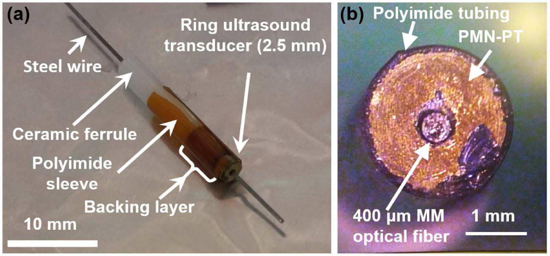
(a) Optical picture of the photoacoustic transducer device showing integration of a 0.4 mm multimode optical fiber, a ring transducer of 0.5 mm inner diameter and 2.5 mm outer diameter, and a ferrule with 2.5 mm outer diameter and 0. 4 mm inner diameter. (b) The front-view of the transducer surface.
C. Diode laser and drive unit
A 905 nm pulsed laser diode (905-D2S3-J09, Laser Components Inc., USA) with 135 W peak optical power is used as the light source. The laser diode is coupled with a multimode optical fiber of 400 μm core diameter with 0.22 mm numerical aperture yielding 65 W peak output power from the fiber. The laser diode is driven by a matchbox sized capacitive discharge circuit which charges a bank of capacitors using the output of a high-volt (up to 80 V) on-board boost converter. The capacitor bank is discharged through the laser diode, whenever triggered by a high-speed high-voltage MOSFET, within a few nanoseconds (~40 ns). During the capacitor discharge, a pulse of ~30-amp current is passed through the laser diode generating an optical pulse with ~2.5 μJ pulse energy. A small pulse generator circuit controls the width and the repetition rate of the pulse.
D. Ultrasound preamp and data acquisition
The received voltage signal from the ultrasound transducer is fed to a pre-amplifier circuit using a coaxial wire. The preamplifier circuit is realized using VCA-2615 IC (Texas, Instruments, USA), which provides two stage amplification of up to 63 dB gain with a variable gain control and an input impedance control functionality. The pre-amplified output is passed through an active low-pass filter to avoid high frequency noises and then level shifted to 0.5 V mean voltage using another op-amp. In order to bring the backend electronics to a wearable form, a high-speed microcontroller-based solution is proposed using LPC4370 microcontroller (NXP Semiconductors, USA). The microcontroller digitizes the analog input between 0.1 V to 0.9 V using a 12-bit on-chip ADC at 80 Msps. However, significant quantization errors were observed in the ADC for sinusoidal inputs above 15 MHz. In future, this limitation will be overcome by implementing an envelope detection stage before the ADC, and then executing fast averaging for up to 10 A-lines at the register level in the ADC, thus allowing reliable on-chip data acquisition for transducer operation up to 20 MHz center frequencies. Furthermore, the microcontroller can function as the central control unit to trigger the laser and move the stages in synchronization, while also communicating the pre-processed imaging data through a wireless module. For current measurements, a commercial data acquisition system with 1 giga samples per second sampling rate (RazaorMax-16, Gage Instruments, USA) is used.
E. Data and power estimations of wPAM system
A power control board is designed with the ability to generate all the DC inputs required for the laser driver, the preamplifier, and the microcontroller unit of the wPAM system. The power control unit is based on three boost converters and one buck converter which provide stable output voltage levels of 16 V, 5 V, 40 V and 2 V for operating the laser driver, the preamplifier,and the microcontroller unit.
Operating at 20 kHz, the laser diode generates 50 mW average optical power. Hence assuming a 30% driver efficiency, it may consume up to 150 mW average power. The VCA-2615 preamplifier was found to consume ~150 mW power, and the microcontroller-based digitization can also be achieved within ~200 mW average power. Therefore, the photoacoustic probe alone is expected to consume ~500 mW average power. Furthermore, the linear ultrasonic stage consumes up to 300 mW power per axis. Hence, the overall power consumption of the proposed wPAM is ~1.1 W during imaging. Assuming a data acquisition rate of 80 Msps with a 12-bit ADC, for imaging up to 5 mm depth (3.2 μs), ~3 kb data will be acquired per A-line. Hence, a ~4.5 Mbps data channel must be established if a 300 px × 300 px region is to be imaged per minute. The data communication requirements can be drastically reduced by on-chip processing of the data to extract only image relevant information.
Integrating all the back-end electronic parts described above with the front-end photoacoustic probe, results in a highly portable and low-cost solution for photoacoustic imaging. However, based on the observations from our current design, each component involved in the wPAM can be improved to achieve further miniaturization. Such possible improvements are discussed later in this paper.
III. Characterization and Photoacoustic Imaging
A. Pulse-echo characterization of the ultrasound transducer
The ring ultrasound transducer was first characterized for its underwater pulse-echo response. A flat aluminum block kept at 7.5 mm distance from the transducer surface was used as an ideal acoustic reflector. A commercial ultrasound pulse-receiver (Model - 5073, Olympus Inc.) was used to provide a voltage pulse input with 2 μJ energy. The output pulse was acquired using an oscilloscope (MDO3024, Tektronix, USA) with 2.5 Giga samples per second sampling rate. The received pulse, observed at the expected delay of 10.3 μs shows ~224 mV peak-to-peak voltage output for 0 dB gain at the pre-amplifier stage (Fig. 5). The frequency response of the received pulse shows that the ring ultrasound transducer has a center frequency of 17.25 MHz. The bandwidth of the transducer, estimated by measuring the frequency range for −6 dB loss in amplitude in the frequency domain, is found to be ~45% (see Fig. 5). The transducer performance shown here can be further improved by incorporating an acoustic lens with optimal matching layer thickness at the center.
Fig. 5.
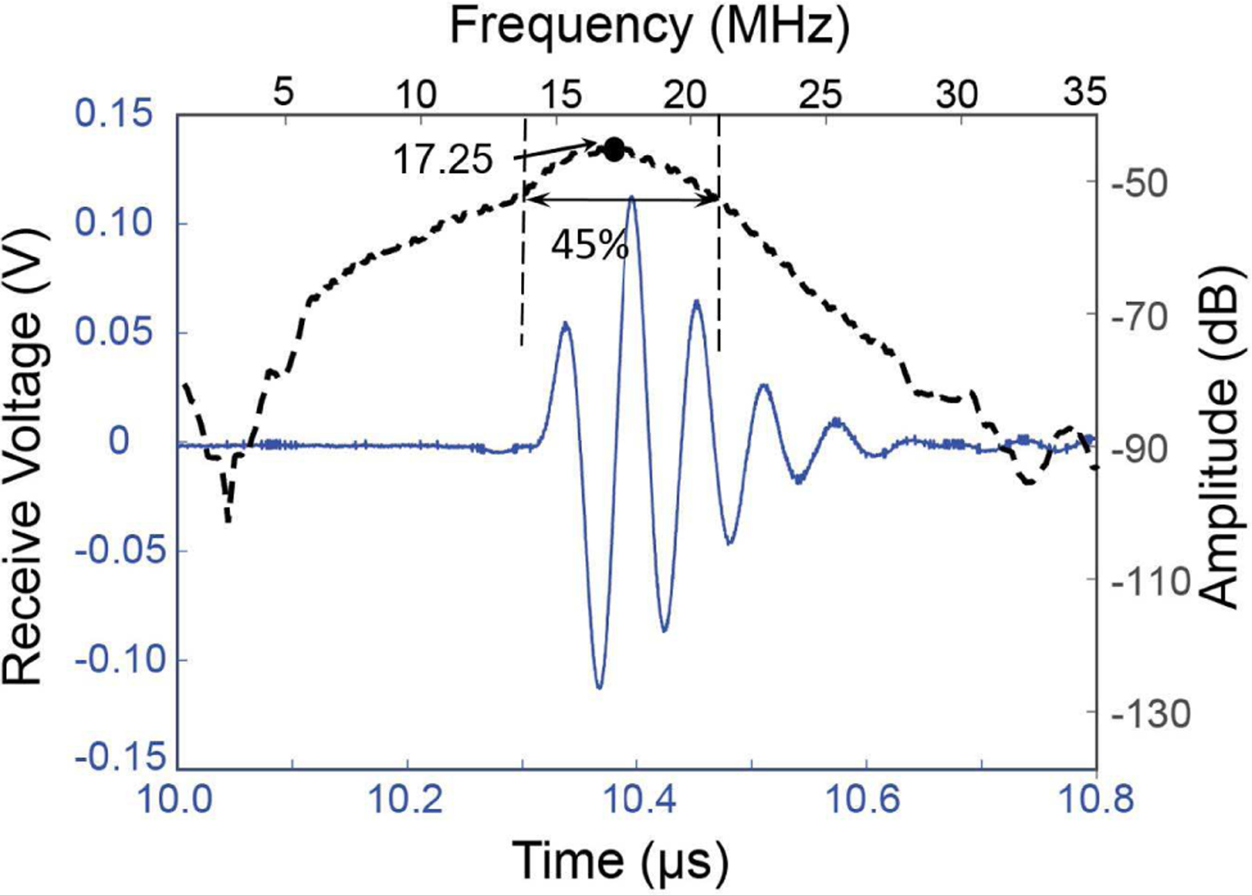
Pulse-echo response of the ring ultrasound transducer shows the center frequency at ~17.25 MHz with ~45% fractional bandwidth.
B. Impedance measurements
The impedance of the ultrasound transducer was measured using a network analyzer (Agilent E5100A/B, Keysights Technologies, CA, USA). The impedance measurements, as provided in Fig. 6, show the expected thickness mode resonance at 17 MHz. The series resonance peak is observed at 15.1 MHz and the parallel resonance peak is observed at 20 MHz. The electromechanical coupling, , estimated using [39],
| 1 |
Fig. 6.

Impedance measurement of the ring ultrasound transducer showing series and parallel resonances at fr = 15.1 MHz and fa = 20 MHz, respectively.
where, fr and fa are the series and parallel resonance frequencies, is found to be 0.48. This is comparable to that of previously reported ultrasound transducers fabricated using PMN-PT as the piezoelectric material [39].
C. Photoacoustic A-line characterization
The ring ultrasound transducer, after integration with the optical fiber of the pulsed laser diode, was further tested for its photoacoustic characteristics. For these measurements, the photoacoustic probe was submerged underwater and placed at ~15 mm distance from a black light absorbing card. The received voltage trace synchronized with the laser excitation, A-line measurement, is shown in Fig. 7a. A sharp pulse with ~7.8 mV peak-to-peak amplitude was observed at the time delay (~10 μs) corresponding to the distance of the card from the probe surface. Due to the low power of the laser diode and unfocused nature of the laser illumination, significant noises were observed in the received photoacoustic signal. 7b. The received pulse shows an almost flat frequency response with ~100% full-width-half-maximum (FWHM) bandwidth (Fig. 7b).
Fig. 7.

(a) Photoacoustic pulse acquired by the photoacoustic probe from a black card placed at 7.5 mm distance. (b) Frequency response of the photoacoustic pulse shows ~100% bandwidth of the probe for PAM.
D. Photoacoustic imaging
The photoacoustic imaging capabilities of the portable system was first tested by integrating the photoacoustic imaging probe with the VCA-2615 based preamplifier described earlier in subsection II-D. An agar phantom consisting of 0.3 mm pencil leads arranged in “PSU” format was prepared, as shown in Fig. 8a. The optical and acoustical properties of agar phantom are very similar to water. In optical regime the phantom is expected to show ~0.15 cm−1 attenuation coefficient and negligible scattering [40]. The photoacoustic probe was mounted on a 3-axis scan system based on a standard stepper motor-based stage (NRT100, Thorlabs, NJ, USA). Using this approach, a 10 mm × 16 mm region was scanned with a 100 μm step size, while the voltage output from the pre-amplifier was recorded using a computer integrated data acquisition system (Razormax 16, Gage Instruments, USA). The VCA-2615 based preamplifier is set to provide 63 dB gain to the ultrasound transducer output. The acquired data was averaged over 100 cycles, in order to reduce the noise floor of the raw data. The maximum peak-to-peak voltage output in a 1 μs time window centered at a time delay corresponding to the distance of the pencil leads from the transducer surface was captured at each scan point. The maximum intensity projection image thus generated is shown in Fig. 8c, clearly identifying the expected “PSU” pattern. The lateral resolution was estimated using the edge spread function across a pencil lead target as marked by a white line in Fig. 8a. The FWHM of the derivative of the fitted edge spread function resulted in the estimated lateral resolution of 0.36 mm. The axial resolution is expected to be 0.88c/BW = 78 μm, where c is the speed of sound and BW is the bandwidth of the transducer. This was found to be in close match with the experimentally observed FWHM of the envelope (~85 μm) of the photoacoustic pulse extracted from the A-line data.
Fig. 8.

Validation of photoacoustic imaging: (a) Picture of the agar phantom with embedded 0.3 mm pencil lead targets arranged in letters “PSU” at 6 mm depth. (b) Photoacoustic amplitude profile across the edge of a pencil lead (shown by dashed line in (a)) along with the derivative of a fitted function showing 0.36 mm FWHM. (c) Photoacoustic image reconstructed from raster 2D scan along x-y plane (16 mm in × and 10 mm in y) with a step size of 100 μm in both the directions.
While the above approach uses a portable and low-cost photoacoustic probe and pre-amplifier, the bulky stepper motor based scanning system imposes a second stage of constraint to the portable and wearable nature of the proposed method. In an attempt to overcome this limitation, an ultra-compact linear ultrasonic motor based approach is investigated using a linear ultrasonic stage (TULA-35, Micromechatraonics, State College, PA) with 5 mm travel range. The motor works on the principle of stick-and-slip motion due to interplay of friction and inertial forces on a mass sliding over a piezoelectrically actuated shaft [41]. This drastically reduces the size of the scanning probe to ~ 1 cm and the weight of the imaging probe head to within 4 gm with the stage weighing only 3.5 gm and the transducer weighing 0.5 gm.
Fig. 9a shows a picture of the photoacoustic imaging probe attached to the miniaturized single axis TULA translational stage. When scanned over a black absorbing strip, the peak-to-peak voltage output corresponding to the photoacoustic response is plotted in Fig. 9b, clearly showing high photoacoustic signal as the probe crosses over the black target. For the measurement shown in Fig. 9b, the scanning was done in a stop-and-capture mode, so that motor position can be correctly estimated, leading to an average scan speed of ~0.1 mm/sec. Once integrated with an optical encoder for position estimation, and stacking two linear ultrasonic stages for raster scanning, the scan speed of up to 15 mm/sec is expected, which implies a frame rate of up to 1 frame/min for a 300 px × 300 px image in a 3 mm × 3 mm scan region with 10 μm resolution.
Fig. 9.
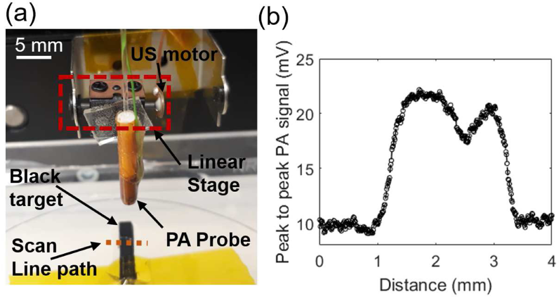
Experimental photoacoustic imaging results for a one dimensional (1-D) scan using a compact ultrasonic motor. (a) Top-view picture of the setup with ring transducer mounted on a piezo motor imaging a 2 mm wide black-card phantom. (b) Peak-to-peak photoacoustic signal amplitude plot along the line (marked with a dotted orange line in (a)) of 4 mm length scanned with a pitch of ~20 μm.
IV. Discussion
Photoacoustic imaging is arguably one of the few non-ionizing, functional and molecular imaging modalities that allows miniaturization at different scales, and it can be used for sub-surface to deep-tissue imaging. There is a need to further advance and scale the PAM technology to a portable and/or wearable form to be suitable for point-of-care applications or deployment of the technology in resource-poor settings or for studying neural activity of awake and behaving mice. The technical advances in optical, ultrasound and other backend mechanical and electrical components have matured to the point where a completely portable and wearable PAM system is feasible. What remains are the investigations, integration, and validation studies of suitable components that meet the portable and wearable requirements. In this paper, we have reported our early efforts towards realizing a portable photoacoustic microscope using low-cost and light-weight components and discussed future directions that likely will help achieve an ultraportable and wearable photoacoustic microscope.
The fiber-coupled laser diode based compact photoacoustic microscopy imaging system presented in this work considered the need to make all other back-end subsystems portable, which included the light source, the laser driver unit, the ultrasound transducer, the pre-amplifying or signal conditioning unit, the digitizer, the image generation and data transfer module, and the probe scanning system. While this work presented a viable approach towards wPAM, each of the above components used in our study can be further optimized to improve the resolution, speed, and portability/wearability of the system.
Table I shows a comparison of the key parameters for the proposed wPAM system with respect to conventional state-of-art table-top PAM systems, and then outlines viable future improvements for each parameter. Considering their output power to weight ratio and low power requirement of microscopy applications, the proposed pulsed laser diodes are the most promising solution for the light source. Although the present approach achieves significant reduction in the size and the cost of the PAM system, the spatial resolution and speed are low due to its unfocused illumination. Bench-top laser powered optical fibers coupled to GRIN lenses on the distal end have been reported to achieve optical resolution PAM systems [40]. Such strategies will be adapted to the proposed fiber-coupled laser diodes to improve spatial resolution as well as signal-to-noise ratio due to optical focusing. Furthermore, the on-microcontroller data acquisition will be implemented by introducing an envelope detection stage between the preamplifier and the ADC, leading to complete miniaturization of the photoacoustic system. The last column of Table 1 shows the expected system parameters after introducing these improvements.
TABLE I.
Comparison of the proposed wPAM with the state-of-the-art PAM systems.
Another important consideration for speed and portability is that of the power and data requirements of the wPAM system. As noted earlier, the power consumption of the current PAM system was limited to ~1.1 W, hence making it suitable for wireless operation for up to an hour using a small lithium-ion battery. Unless truncated, raw volumetric data corresponding to a reasonable 10,000-pixel scan with 5 mm depth can be > 10 Gb in size. Hence, for a wearable system, it will be more reasonable to define a desirable depth around which the received A-line data can be projected using a maximum amplitude projection algorithm, and transferred to a server via a USB or wireless connection.
V. Conclusions
A viable approach to develop a low-cost, portable and wearable photoacoustic imaging microscope is presented. To achieve this, the photoacoustic microscope probe head is miniaturized by integrating a 400 μm core diameter optical fiber that was coupled to the laser diode with an in-house fabricated PMN-PT ring ultrasound transducer of 2.5 mm diameter. The transducer is centered at ~17.25 MHz and shows ~45% and ~100% fractional bandwidths for ultrasound pulse-echo response and photoacoustic pulse response respectively. A system level approach is proposed to achieve fully portable PAM system, by using a small pulsed laser diode as the light source, an ultra-compact linear ultrasonic stage for scanning the microscope probe and on-board pre-amplifier coupled to the microcontroller based data acquisition and reconstruction. In future, the focused light at the fiber output is expected to improve the resolution, the signal strength and speed of imaging.
Acknowledgment
The authors would like to thank Eugene Gerber for his help and advice in ultrasound transducer fabrication.
This work was supported by the National Institute of Biomedical Imaging and Bioengineering (NIBIB), National Institute of Health (NIH), U.S. under Grant R00EB017729-04.
Biographies

Ajay Dangi received his B. Tech. degree in Mechanical Engineering from Indian Institute of Technology, Varanasi, in 2010 and the Ph.D. degree in mechanical engineering in 2016 from Indian Institute of Science, Bangalore. From 2016 to 2017 he was a research assistant in the MEMS lab at the Center for Nano Science and Engineering in Indian Institute of Science, Bangalore. From 2017, he has been working as a postdoctoral scholar in the Department of Biomedical Engineering at the Pennsylvania State University, State College. His research interests include photoacoustic and ultrasound imaging, MEMS and MOEMS sensors, PMUTs, and acoustics.

Sumit Agrawal received his B. Tech degree in Electronics and Communication in 2012 from GLA Institute, Mathura (India). While there, he did research on decoding algorithms for quasi-cyclic low-density parity check codes. Later, he earned an M. Tech in Media and Sound Engineering from I.I.T Kharagpur, India in 2014 doing research on rate control of H.264 and High Efficiency Video Coding. He then worked for a year in KLA Tencor where he explored image-processing algorithms for defect inspection in silicon wafers during IC fabrication. He later joined SkinCurate Research, India based smart medical imaging devices startup, where he developed interest in medical imaging and machine learning. Sumit joined Dr. Kothapalli’s group as a PhD student in Spring-2017 and is currently focused on developing dual modality ultrasound and photoacoustic imaging hardware as well as image reconstruction software.

Gaurav Ramesh Datta received his B. Tech. degree in electrical engineering from College of Engineering Pune, an autonomous institute of Government of Maharashtra affiliated to Savitribai Phule Pune University in 2016. Since 2017, he is enrolled at Pennsylvania State University, University Park, Pennsylvania pursuing M.S. degree. He has been working as a research assistant in the Biophotonics and Ultrasound Imaging Lab at Pennsylvania State University since May 2018.

Visweshwar Srinivasan received his B.E. degree in electronics and communication engineering from Anna University, Chennai, India, in 2016. He is currently pursuing the MS. degree in Electrical engineering at Pennsylvania State University, University Park, Pennsylvania, USA. In 2015, he was a Research Intern with the Oil and Natural Gas Corporation Ltd, Chennai, India. His research interest includes the development of embedded systems for biological/medical treatment techniques using ARM controllers and implementing high-speed analog to digital converters using multicore microcontrollers.

Sri-Rajasekhar Kothapalli received his Ph.D in Biomedical Engineering from the Washington University in Saint Louis in 2009. After that, he carried out his postdoctoral research from 2009 to 2013 at Stanford University. From 2014 to 2016, he served as an instructor in the Department of Radiology, Stanford University. His research work spans various biomedical imaging techniques including photoacoustic imaging, ultrasound imaging, and ultrasound-modulated optical tomography (UOT). Working at the interface of MEMS ultrasound transducer and photoacosutic imaging, he developed CMUT based dual modality transrectal ultrasound and photoacoustic (TRUSPA) imaging device for prostate cancer screening, and conducted clinical studies on several prostate cancer patients using the TRUSPA device. He is currently working as an assistant professor in the department of biomedical engineering at the Pennsylvania State University, State College.
Contributor Information
Ajay Dangi, Department of Biomedical Engineering, Pennsylvania State University, University Park, USA..
Sumit Agrawal, Department of Biomedical Engineering, Pennsylvania State University, University Park, USA..
Gaurav Ramesh Datta, School of Electrical Engineering and Computer Science, Pennsylvania State University, University Park, USA..
Visweshwar Srinivasan, School of Electrical Engineering and Computer Science, Pennsylvania State University, University Park, USA..
Sri-Rajasekhar Kothapalli, Department of Biomedical Engineering, Pennsylvania State University, University Park, USA and Penn State Cancer Institute, Pennsylvania State University, Hershey, Pennsylvania, USA..
References
- [1].Maslov K, Stoica G, and V Wang L, “In vivo dark-field reflection-mode photoacoustic microscopy.,” Opt. Lett, vol. 30, no. 6, pp. 625–7, 2005. [DOI] [PubMed] [Google Scholar]
- [2].Zhang HF, Maslov K, Stoica G, and Wang LV, “Functional photoacoustic microscopy for high-resolution and noninvasive in vivo imaging,” Nat. Biotechnol, vol. 24, no. 7, pp. 848–851, July 2006. [DOI] [PubMed] [Google Scholar]
- [3].Beard P, “Biomedical photoacoustic imaging,” Interface Focus, vol. 1, no. 4, pp. 602–631, 2011. [DOI] [PMC free article] [PubMed] [Google Scholar]
- [4].Cox B, Laufer JG, Arridge SR, and Beard PC, “Quantitative spectroscopic photoacoustic imaging: a review,” J. Biomed. Opt, vol. 17, no. 6, p. 061202, 2012. [DOI] [PubMed] [Google Scholar]
- [5].Schwaighofer A, Brandstetter M, and Lendl B, “Quantum cascade lasers (QCLs) in biomedical spectroscopy,” Chem. Soc. Rev, vol. 46, no. 19, pp. 5903–5924, October 2017. [DOI] [PubMed] [Google Scholar]
- [6].Li J, Chen W, and Yu B, “Recent Progress on Infrared Photoacoustic Spectroscopy Techniques,” Appl. Spectrosc. Rev, vol. 46, no. 6, pp. 440–471, August 2011. [Google Scholar]
- [7].Zhang HF, Maslov K, and Wang LV, “In vivo imaging of subcutaneous structures using functional photoacoustic microscopy,” Nat. Protoc, vol. 2, no. 4, pp. 797–804, 2007. [DOI] [PubMed] [Google Scholar]
- [8].Wang LV and Hu S, “Photoacoustic tomography: In vivo imaging from organelles to organs,” Science, vol. 335, no. 6075 pp. 1458–1462, 2012. [DOI] [PMC free article] [PubMed] [Google Scholar]
- [9].Levi J et al. , “Design and Synthesis of an Activatable Photoacoustic Probe,” Mol. Imaging, vol. 132, no. 14, pp. 1–20, 2010. [Google Scholar]
- [10].Kothapalli SR et al. , “Simultaneous Transrectal Ultrasound and Photoacoustic Human Prostate Imaging,” Sci. Transl. Med (in Press). [DOI] [PubMed] [Google Scholar]
- [11].Chen CL, Wang CY, Chu C, Su LH, and Chiu CH, “Functional and molecular characterization of pSE34 encoding a type IV secretion system in Salmonella enterica serotype enteritidis phage type 34,” in FEMS Immunology and Medical Microbiology, vol. 57, no. 3, 2009, pp. 274–283. [DOI] [PubMed] [Google Scholar]
- [12].Mehrmohammadi M, Joon Yoon S, Yeager D, and Emelianov SY, “Photoacoustic Imaging for Cancer Detection and Staging,” Curr. Mol. Imaging, vol. 2, no. 1, pp. 89–105, March 2013. [DOI] [PMC free article] [PubMed] [Google Scholar]
- [13].Wong TTW et al. , “Fast label-free multilayered histology-like imaging of human breast cancer by photoacoustic microscopy,” Sci. Adv, vol. 3, no. 5, p. e1602168, May 2017. [DOI] [PMC free article] [PubMed] [Google Scholar]
- [14].Zemp RJ, Song L, Bitton R, Shung KK, and Wang LV, “Realtime Photoacoustic Microscopy of Murine Cardiovascular Dynamics,” Opt. Express, vol. 16, no. 22, p. 18551, October 2008. [DOI] [PMC free article] [PubMed] [Google Scholar]
- [15].Yang J et al. , “Motionless volumetric photoacoustic microscopy with spatially invariant resolution,” Nat. Commun, vol. 8, no. 1, 2017. [DOI] [PMC free article] [PubMed] [Google Scholar]
- [16].Allen TJ et al. , “Ultrafast laser-scanning optical resolution photoacoustic microscopy at up to 2 million A-lines per second,” J. Biomed. Opt, vol. 23, no. 12, p. 1, December 2018. [Google Scholar]
- [17].Yao J et al. , “High-speed label-free functional photoacoustic microscopy of mouse brain in action,” Nat. Methods, vol. 12, no. 5, pp. 407–410, 2015. [DOI] [PMC free article] [PubMed] [Google Scholar]
- [18].Wang LV, “Multiscale photoacoustic microscopy and computed tomography,” Nat. Photonics, vol. 3, no. 9, pp. 503–509, 2009. [DOI] [PMC free article] [PubMed] [Google Scholar]
- [19].Xie Z, Jiao S, Zhang HF, and Puliafito CA, “Laser-scanning optical-resolution photoacoustic microscopy,” Opt. Lett, vol. 34, no. 12, p. 1771, 2009. [DOI] [PubMed] [Google Scholar]
- [20].Zong W et al. , “Fast high-resolution miniature two-photon microscopy for brain imaging in freely behaving mice,” Nat. Methods, vol. 14, no. 7, pp. 713–719, July 2017. [DOI] [PubMed] [Google Scholar]
- [21].Kobayashi T et al. , “Wide and Deep Imaging of Neuronal Activities by a Wearable NeuroImager Reveals Premotor Activity in the Whole Motor Cortex,” Sci. Rep, vol. 9, no. 1, p. 8366, December 2019. [DOI] [PMC free article] [PubMed] [Google Scholar]
- [22].Sakadžić S, “At long last, PAT hats for the lab rats,” Journal of Cerebral Blood Flow and Metabolism, vol. 35, no. 8 p. 1223, 2015. [DOI] [PMC free article] [PubMed] [Google Scholar]
- [23].Dangi A et al. , “Evaluation of High Frequency Piezoelectric Micro-machined Ultrasound Transducers for Photoacoustic Imaging,” in 2018 IEEE Sensors, New Delhi, 2018, pp. 1–4. [DOI] [PMC free article] [PubMed] [Google Scholar]
- [24].Kothapalli SR et al. , “Deep Tissue Photoacoustic Imaging Using a Miniaturized 2-D Capacitive Micromachined Ultrasonic Transducer Array,” IEEE Trans. Biomed. Eng, vol. 59, no. 5, pp. 1199–1204, May 2012. [DOI] [PMC free article] [PubMed] [Google Scholar]
- [25].Dangi A et al. , “Ring PMUT array based miniaturized photoacoustic endoscopy device,” in Photons Plus Ultrasound: Imaging and Sensing 2019, 2019, vol. 10878, p. 35. [Google Scholar]
- [26].Nikoozadeh A et al. , “Photoacoustic imaging using a 9F microLinear CMUT ICE catheter,” in IEEE International Ultrasonics Symposium, IUS, 2012, pp. 24–27. [Google Scholar]
- [27].Shung KK et al. , “Catheter-based photoacoustic endoscope,” J. Biomed. Opt, vol. 19, no. 6, p. 066001, 2014. [DOI] [PMC free article] [PubMed] [Google Scholar]
- [28].Yang JM et al. , “Three-dimensional photoacoustic endoscopic imaging of the rabbit esophagus,” PLoS One, vol. 10, no. 4, p. e0120269, April 2015. [DOI] [PMC free article] [PubMed] [Google Scholar]
- [29].Dangi A, Agrawal S, Lieberknecht J, Zhang J, and Kothapalli SR, “Ring Ultrasound Transducer Based Miniaturized Photoacoustic Imaging System,” in 2018 IEEE Sensors, New Delhi, 2018, pp. 1–4. [DOI] [PMC free article] [PubMed] [Google Scholar]
- [30].Yang J-M et al. , “Photoacoustic endoscopy,” Opt. Lett, vol. 34, no. 10, p. 1591, 2009. [DOI] [PMC free article] [PubMed] [Google Scholar]
- [31].Yang J-M et al. , “Simultaneous functional photoacoustic and ultrasonic endoscopy of internal organs in vivo,” Nat. Med, vol. 18, no. 8, pp. 1297–1302, August 2012. [DOI] [PMC free article] [PubMed] [Google Scholar]
- [32].Yoon T-J, “Recent advances in photoacoustic endoscopy,” World J. Gastrointest. Endosc, vol. 5, no. 11, p. 534, 2014. [DOI] [PMC free article] [PubMed] [Google Scholar]
- [33].Sanders JL et al. , “A handheld 1D transparent CMUT array probe for photoacoustic imaging,” in IEEE International Ultrasonics Symposium, IUS, 2017. [Google Scholar]
- [34].Zhen Q and Piyawattanamatha W, “New endoscopic imaging technology based on MEMS sensors and actuators,” Micromachines, vol. 8, no. 7, 2017. [DOI] [PMC free article] [PubMed] [Google Scholar]
- [35].Bui NQ et al. , “Intravascular ultrasonic-photoacoustic (IVUP) endoscope with 2.2-mm diameter catheter for medical imaging,” Comput. Med. Imaging Graph, vol. 45, pp. 57–62, 2015. [DOI] [PubMed] [Google Scholar]
- [36].Park SE and Shrout TR, “Characteristics of relaxor-based piezoelectric single crystals for ultrasonic transducers,” IEEE Trans. Ultrason. Ferroelectr. Freq. Control, vol. 44, no. 5, pp. 1140–1147, September 1997. [Google Scholar]
- [37].Zhang S and Shrout TR, “Relaxor-PT single crystals: observations and developments,” IEEE Trans. Ultrason. Ferroelectr. Freq. Control, vol. 57, no. 10, pp. 2138–2146, October 2010. [DOI] [PMC free article] [PubMed] [Google Scholar]
- [38].Yang J-M et al. , “A 2.5-mm diameter probe for photoacoustic and ultrasonic endoscopy.,” Opt. Express, vol. 20, no. 21, pp. 23944–53, 2012. [DOI] [PMC free article] [PubMed] [Google Scholar]
- [39].Zhou Q et al. , “PMN-PT single crystal, high-frequency ultrasonic needle transducers for pulsed-wave Doppler application,” IEEE Trans. Ultrason. Ferroelectr. Freq. Control, vol. 54, no. 3, pp. 668–673, 2007. [DOI] [PubMed] [Google Scholar]
- [40].Aranda-Lara L, Torres-García E, and Oros-Pantoja R, “Biological Tissue Modeling with Agar Gel Phantom for Radiation Dosimetry of 99mTc,” Open J. Radiol, vol. 04, no. 01, pp. 44–52, 2014. [Google Scholar]
- [41].Hunstig M, “Piezoelectric Inertia Motors—A Critical Review of History, Concepts, Design, Applications, and Perspectives,” Actuators, vol. 6, no. 1, p. 7, 2017. [Google Scholar]
- [42].Erfanzadeh M, Kumavor PD, and Zhu Q, “Laser scanning laser diode photoacoustic microscopy system,” Photoacoustics, vol. 9, pp. 1–9, March 2018. [DOI] [PMC free article] [PubMed] [Google Scholar]
- [43].Guo Z, Li Y, and Chen S-L, “Miniature probe for in vivo opticaland acoustic-resolution photoacoustic microscopy,” Opt. Lett, vol. 43, no. 5, p. 1119, March 2018. [DOI] [PubMed] [Google Scholar]