

1. INTRODUCTION
Kidney stones currently affect 1 in 11 Americans over their lifetime,1 and the prevalence is rising. Introduced in the 1980s, shock wave lithotripsy (SWL) is the only completely noninvasive treatment for kidney stones.2 In SWL, an electrohydraulic, electromagnetic, or piezoelectric source outside the patient generates shock waves that are focused on the kidney stone to shatter it into small fragments.3 However, SWL has problems such as difficulty in coupling, mistargeting or renal injury. Hence, Maxwell et al. introduced a new technology called burst wave lithotripsy(BWL) which attempts to avoid some shortcomings of SWL.4 BWL has proven to be effective in fragmenting different kinds of human stones. The technology is still under development, and clinical safety and efficacy are being investigated as reported in papers in this special session “ Shock Waves and Ultrasound for Calculus Fragmentation.”5,6
One of the challenges of BWL is that the size of the stone it can fragment in vivo, especially in the pig model, is constrained by the size of the transducer focus in the same way as in SWL as discussed by Thomas et al. in this special session.7 For effective fragmentation of a stone, the stone needs be within the focal region (the volume defined by the −6dB contour of the pressure peak). The size of the focal region produced by a conventionally designed spherically focused transducer is dependent on focal distance, aperture of the transducer, and frequency of the wave. For in vivo experiments (farm pigs, a common animal model for lithotripsy studies), the available acoustic window is small (~80 mm), and focal plane distance cannot be varied over a broad range as the kidney stone is located 50 to 60 mm deep. In addition, the size of fragments of a stone is dependent on the center frequency of the bursts; a higher frequency exposure generates proportionately smaller fragments.4 Currently, frequencies between 300 kHz and 400 kHz are being studied as they produce fragments small enough to pass spontaneously and fragment a stone within a time window comparable to SWL in vitro. These constraints limit the aperture of the transducer, distance of focal plane, and frequency to obtain a focus of approximately 6 mm lateral width. However, 97% of the stones considered for a surgical intervention have dimensions larger than 5 mm.8
Hence, we researched a different technique to produce larger focal regions within the abovementioned constraints. We used the iterative angular spectrum approach (IASA), as described by Melde et al., to generate desire pressure profiles in focal plane of a transducer.9 In addition, we weighted the desired pressure profiles to generate focal regions larger than 6 mm in a focal plane. A BWL transducer was fabricated and coupled to a lens designed with the IASA. The transducer was characterized to confirm the simulation predicting a focal width of 12 mm in the focal plane. Finally, we fragmented large artificial plaster stones in vitro and compared the rate of fragmentation with an existing equivalent BWL transducer coupled to a conventional spherical lens.
2. METHODS
A. FOCUS ENLARGEMENT WITH IASA
The IASA was implemented in a scientific computing program (MATLAB®) as per the algorithm described by Melde et al.9 The algorithm was given two inputs – pressure amplitude distribution of the source and desired pressure amplitude distribution, referred to as the desired image, in the focal plane. The program calculated the required phase distribution at the surface of the source to produce the desired pressure distribution in the focal plane. The implementation was validated with a desired complex binary image. The pressure amplitude distribution of the source was set as a circle with 80 mm diameter and uniform pressure as shown in Figure 1(a). To obtain foci larger than 6 mm in diameter, desired images in the focal plane (located between 80 and 90 mm) were set as a circle with diameters ranging between 6 mm and 20 mm. Figure 1(b) shows a desired image with 12 mm diameter. Next, the circles were weighted with higher values in regions near the perimeter. To optimize the results further, we shifted the center of the circles from (0,0) to (p,p) where p was varied from 0 to 9 mm. Based on the simulations of these inputs, the desired pressure profile was modified to an image containing four smaller circles (Figure 1(c)) located at (±x-p, ±y-p) where x and y varied from 0 to 9 mm. The diameter of small circles was varied from 2 mm to 8 mm.
Figure 1:
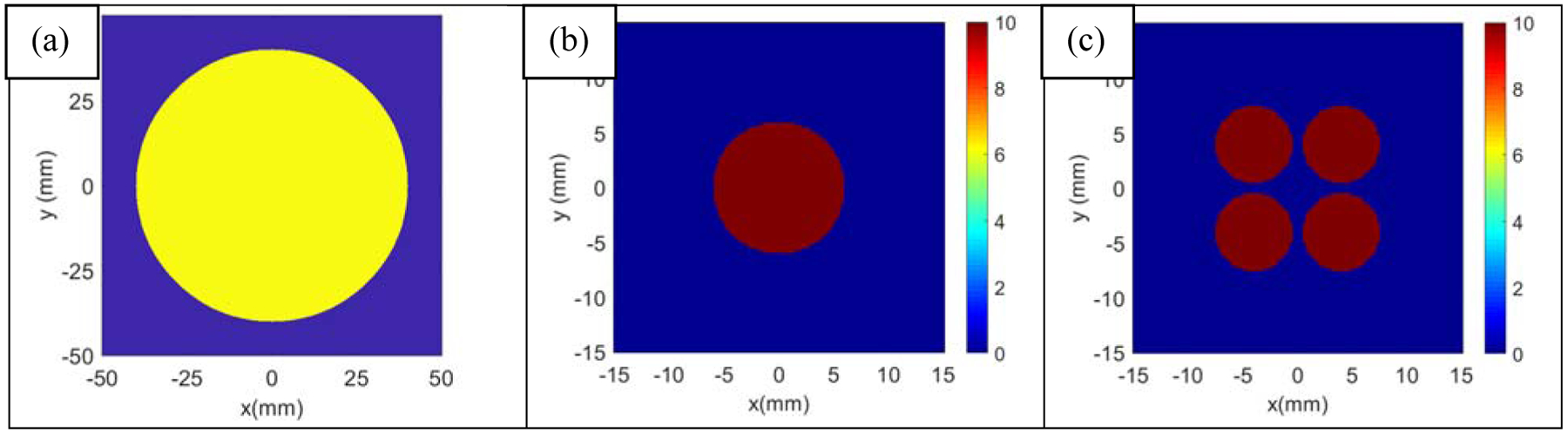
For enlarging foci with IASA, the algorithm was given two inputs: source pressure amplitude distribution and desired pressure amplitude distribution in the focal plane, referred to as thedesired image. (a) Source pressure profile with 80 mm diameter (b) Desired image with 12 mm (c) Desired Image with 4 small circles
The phase distribution was realized with a lens made from Veroclear®, a photopolymer used in 3D printing (3D Systems, Rock Hill, SC). The lens was fabricated with a rapid prototyping machine (Objet30 Pro, Stratasys, Eden Prairie, MN). An unfocussed ultrasound transducer (center frequency (f) = 335 kHz, aperture diameter (2a) = 90 mm) was designed and fabricated and was then coupled with different lenses to test pressure profiles produced by them. The lenses were coupled to the transducer with water as an intermediate layer of approximately 3 mm thickness. The transducer was operated between 300 kHz and 400 kHz and about the third harmonic (1 MHz) for the complex image. The pressure profiles were scanned in an 80-liter water tank with a hydrophone (HNR-0500, Onda, Sunnyvale, CA).
B. FRAGMENTATION OF LARGE STONES
Once an optimal pressure profile of a large focus was obtained, a BWL transducer was fabricated as discussed by Kim et al.;10 its schematic is shown in Figure 2(a). Artificial plaster stones made from Begostone Plus (Bego USA, Lincoln, RI), a gypsum-based plaster, were formed into cylinders with dimensions: 11 mm length × 6 mm diameter (avg. weight = 0.690 ± 0.011 g). The new BWL transducer was set up in a water tank shown in Figure 2(b). Water in the tank was degassed to maintain a gas concentration below 30% of the saturation level of dissolved oxygen measured with an oxygen level meter (Oxi 330i meter with a CellOx 325 probe, WTW, Weilheim, Germany). The stones were fragmented with the new BWL transducer as well as with the existing conventionally focused BWL transducer which had a focus of 6 mm diameter in the focal plane. Both transducers were operated at 350 kHz with a pulse repetition frequency of 20 and at the same negative pressure amplitude (−4.9 MPa) for 30 minutes. The stones were held in a hemispherically shaped mesh basket made from nylon strands with 2 mm pores and a 35 mm diameter. The weight of fragments larger than 2 mm was measured every 10 minutes. The ratio of the weight of fragments greater than 2 mm to the weight of the stone prior to exposure was calculated as a fragmentation metric. The ratio (Wi – Wf) / Wi reflects efficiency of the fragmentation as a fraction of the stone considered sufficiently fragmented for natural passage through the urinary tract, where Wi is the initial weight and Wf is the weight of remaining fragments greater than 2 mm after the exposure. The means and standard deviations of different conditions were analyzed statistically with a Student’s t-test and p-values are reported.
Figure 2:
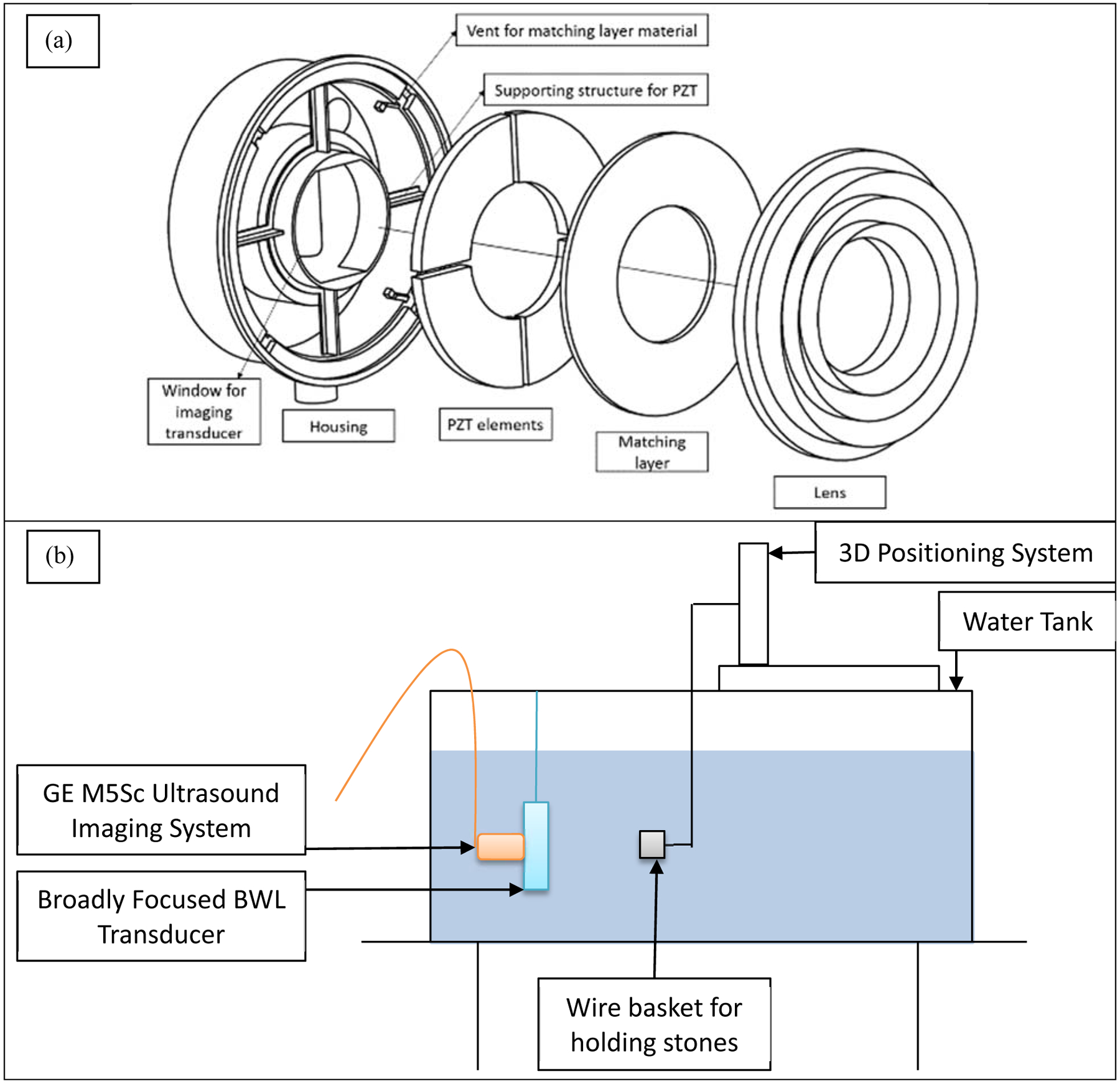
Experimental setup schematics: (a) Exploded view of new BWL transducer (b) Setup for fragmenting stones.
3. RESULTS
A. VALIDATION
To validate the implementation of the algorithm with an arbitrary image, the desired pressure profile was set to a complex image (Figure 3(a)) and the frequency was set to 1 MHz to achieve higher resolution. The simulated and measured results are shown in Figure 3(b) and (c), respectively.
Figure 3:
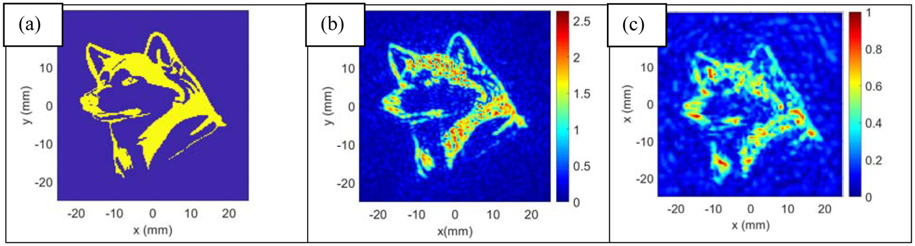
The iterative angular spectrum approach was implemented and validated for generating complex pressure profiles. (a) Desired complex image in the focal plane of a transducer (b) Simulated pressure profile (c) Measured pressure profile
B. ENLARGEMENT OF FOCUS
When the desired images had a circle with diameters larger than 6 mm, it was observed that the output of the algorithm converged to a solution similar to the desired image having a circle of diameter 6 mm with no enlargement of the focus in the focal plane (Figure 4(a) and (b)).
Figure 4:
To obtain a larger focus with IASA, the desired images were set similar to that in Figure 1(b). When the diameter of the circle in desired image was 6 mm, it simulated pressure field as shown in (a). When diameter of the circle in the desired image was varied from 6 to 20 mm, the simulated results were similar to those simulated at 6 mm diameter. (b) shows results of simulation of a desired image with a 12 mm diameter. When the center of the circle with 18 mm diameter in the desired image was shifted to (4,4), the simulated pressure profile was as shown in (c). Introducing asymmetry in the pressure profile changed the results of simulations significantly.
For circles with diameter greater than 16 mm, it was found that the maximum pressure along the z-axis was farther from desired focal plane. The plane located at 15 mm from the desired focal plane had a higher maximum pressure amplitude than that of desired focal plane.
Further, different weighting functions were laid over the circular shape in the desired image plane – concentric circular shapes having different pressure levels. However, these attempts led to solutions similar to results in diameters ranging from 6 mm to 20 mm, and the size of the focus did not increase.
When asymmetry was introduced by shifting center of the desired image, convergence to different solutions was observed. The size of the focus was large and the farthest points were 18 mm apart (Figure 4(c)). Also, the highest-pressure amplitude was located in the desired focal plane.
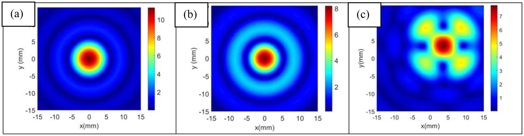
It was found that the annular pressure profile with a focal width of 12 mm can be achieved at 350 kHz with a focal gain of 5.5 at a focal distance of 84 mm. The pattern is reminiscent of a vortex beam pattern,11 although slightly wider than would be expected for a symmetric vortex. The centers of small circles in the desired image were located at (±3–3.5 mm, ±3–3.5 mm) and their diameter was 6 mm. Inner and outer diameters of source profile were 40 mm and 80 mm respectively. Figure 5(a) and (b) show simulated and measured pressure profiles in the focal plane. The difference in the simulated and measured focal width was ≤1 mm, and the structural-similarity index value was greater than 0.65. The differences in structures are due not to shape and size of focus but to amplitude distribution within the focal region.
Figure 5:
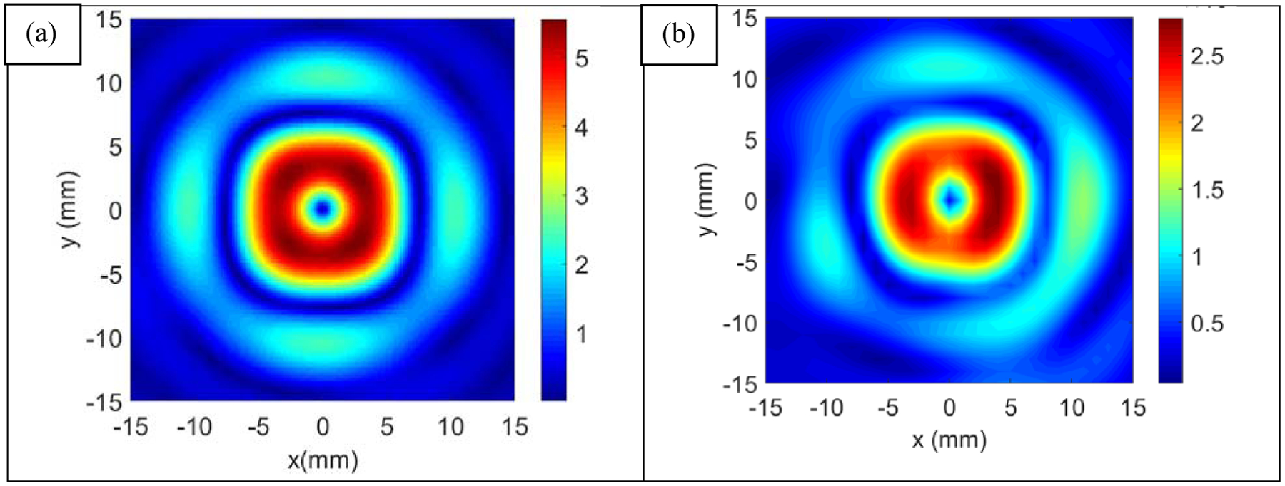
The optimized beam pattern was obtained when the desired image was set similar to Figure 1(c) and parameters like location of centers of circles, asymmetric shift in center of the circles, diameters of the circles were varied. (a) shows simulated results for small circles with 6 mm diameter and centers located at (±3 – 3.5 mm, ±3 – 3.5 mm). Focal plane of the transducer was scanned to confirm the simulation and measured result is shown in (b).
C. FRAGMENTATION OF STONES
The stones were fragmented with a transducer producing an annular pressure profile. The results are shown in Figure 6. The new transducer fragmented 44 ± 9 % of a stone by weight in 30 minutes whereas the conventionally focused transducer fragmented only 16 ± 4 % of the stone in the same duration. The rates of fragmentation with the new and existing transducers were 9.9 ± 2.0 mg/min and 3.6 ± 0.9 mg/min, respectively. However, the rate of fragmentation varied over time. For the broadly focused transducer, the average rate of fragmentation was 7.9 ± 1.7 mg/min in the first 10 minutes and 11.4 ± 2.6 mg/min in the last 10 minutes. The rate didn’t change significantly for the existing transducer. It increased from 3.1 ± 0.4 mg/min to 4.1 ± 0.9 mg/min for the same time windows.
Figure 6:
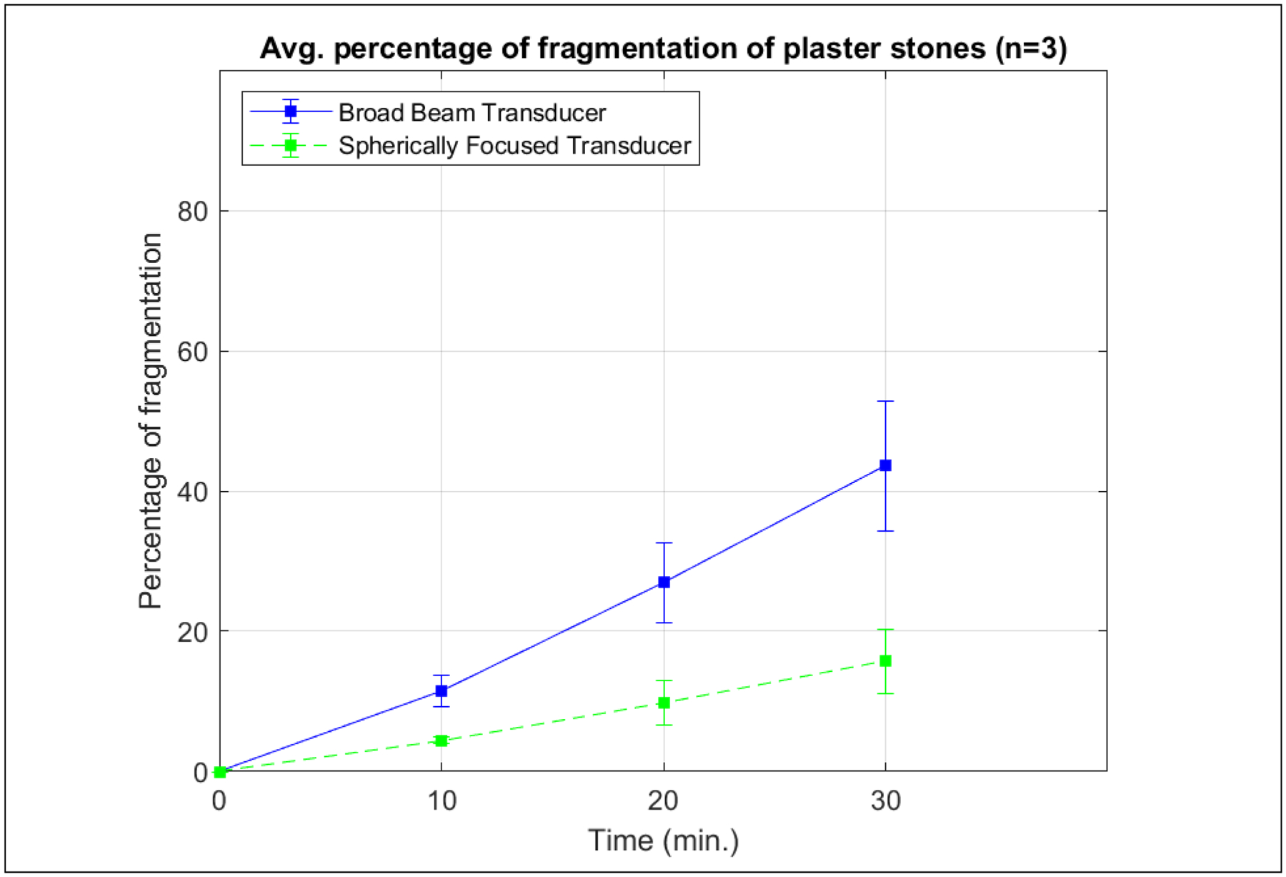
Artificial plaster stones which mimic human stones were fragmented with the broadly focused transducer (focal width ~ 11 mm) and conventionally focused transducer with spherical lens (focal width = 6 mm). The cylindrical stones had diameter of 6 mm and length of 11 mm. They were fragmented for half an hour and the weight of fragments smaller than 2 mm was measured every 10 minutes. The transducers were operated at 350 kHz with a pulse repetition frequency of 20 Hz and at the same negative pressure amplitude (−4.9 MPa). The broadly focused transducer fragmented 44 ± 9 % of stone by weight in 30 minutes whereas the existing transducer fragmented only 16 ± 4 % of the stone in the same duration.
4. CONCLUSION
The iterative angular spectrum approach (IASA) is useful for generating complex pressure fields. However, to generate features comparable to the wavelength in the medium, it is also useful to introduce weighting functions and asymmetry in desired images. This technique was used to enlarge the size of the focus of a BWL transducer which is otherwise constrained to 6 mm with conventional spherical or spheroidal lenses. Based on the observations of the rate of fragmentation, the new broadly focused transducer can fragment the stones 2.8 times faster than a conventionally focused transducer. Thus, the broadly focused transducer may reduce treatment time for large stones substantially.
ACKNOWLEDGMENTS
We acknowledge funding support from NIH through NIDDK P01-DK043881 and K01-DK104854.
REFERENCES
- 1.Scales CD et al. Prevalence of kidney stones in the United States. Eur. Urol 62, 160–5 (2012). [DOI] [PMC free article] [PubMed] [Google Scholar]
- 2.Chaussy C, Brendel W & Schmiedt E EXTRACORPOREALLY INDUCED DESTRUCTION OF KIDNEY STONES BY SHOCK WAVES. Lancet 316, 1265–1268 (1980). [DOI] [PubMed] [Google Scholar]
- 3.Bailey MR, Mcateer JA, Pishchalnikov YA, Hamilton MF & Colonius T PROGRESS IN LITHOTRIPSY RESEARCH. Acoust. Today 2, 18–29 (2006). [Google Scholar]
- 4.Maxwell AD et al. Fragmentation of urinary calculi in vitro by burst wave lithotripsy. J. Urol 193, 338–44 (2015). [DOI] [PMC free article] [PubMed] [Google Scholar]
- 5.Wang Y-N et al. An in vivo demonstration of efficacy and acute safety using a porcine model. J. Acoust. Soc. Am 144, 1780 (2018). [DOI] [PMC free article] [PubMed] [Google Scholar]
- 6.Bailey MR et al. Update on clinical trials results of kidney stone repositioning and preclinical results of stone breaking with one ultrasound system. J. Acoust. Soc. Am 144, 1779 (2018). [DOI] [PMC free article] [PubMed] [Google Scholar]
- 7.Thomas G, Chapelon J, Birer A & Lafon C Confocal lens focused piezoelectric lithotripter. J. Acoust. Soc. Am 144, 1780–1781 (2018). [DOI] [PubMed] [Google Scholar]
- 8.Tiselius H & Andersson A Stone Burden in an Average Swedish Population of Stone Formers Requiring Active Stone Removal: How Can the Stone Size Be Estimated in the Clinical Routine? Eur. Urol 43, 275–281 (2003). [DOI] [PubMed] [Google Scholar]
- 9.Melde K, Mark AG, Qiu T & Fischer P Holograms for acoustics. Nature 537, 518–522 (2016). [DOI] [PubMed] [Google Scholar]
- 10.Kim Y et al. Rapid prototyping fabrication of focused ultrasound transducers. IEEE Trans. Ultrason. Ferroelectr. Freq. Control 61, 1559–1574 (2014). [DOI] [PubMed] [Google Scholar]
- 11.Cain CA & Umemura S Concentric-Ring and Sector-Vortex Phased-Array Applicators for Ultrasound Hyperthermia. IEEE Trans. Microw. Theory Tech 34, 542–551 (1986). [Google Scholar]