Abstract
Ni-rich cathode is one of the promising candidate for high-energy lithium-ion batteries. In this work, we prepare the different super-P carbon black amounts [0.1 (SPB 0.1 wt%), 0.3 (SPB 0.3 wt%), 0.5 (SPB 0.5 wt%) and 0.7 wt% (SPB 0.7 wt%)] of carbon coated LiNi0.8Co0.1Mn0.1O2 (NCM811) cathodes and their electrochemical performances are investigated. Carbon coating does not change the crystal structure and morphology of NCM811. Among the coated NCM811, the SPB 0.5 wt% NCM811 delivers the excellent cyclability (87.8% after 80 cycles) and rate capability (86.5% at 2 C) compared to those of pristine NCM811. It is ascribed to that the carbon coating not only increase the Li ion and electron transfer as well as protect the NCM811 cathode materials from side reaction at the electrolyte/NCM811 interface. Therefore, we can conclude that the appropriate amount of carbon coating can be regarded as an effective approach for Ni-rich NCM cathode.
Subject terms: Energy science and technology, Materials science
Introduction
The demand of lithium-ion batteries (LIBs) has been intensively increasing with growing large-scale devices such as electric vehicles (EVs) and energy storage systems (ESSs). Moreover, the high-energy density and long-life LIBs are required for market expansion. To meet the requirements, various cathodes have been studied to increase the energy density of LIBs. Among the cathode materials, Ni-rich NCM cathodes have been considerably researched for high-energy LIBs due to higher specific capacity, relatively low cost and environmental factor compared to other cathode materials1. However, Ni-rich NCM cathodes (Ni ≥ 80%) suffer from some problems such as poor cycle life and capacity fading, which limit their commercialization. It is associated with cation mixing, side reactions and residual lithium compounds such as LiOH and Li2CO3 on the surface of Ni-rich cathodes2–6.
To address these problems, many researchers have attempted cation/anion doping for composition modification, surface coating, core–shell and concentration-gradient structures. Among them, the surface-modification with conductive materials such as metal oxides (Al2O37, ZrO28, TiO29, SiO210), metal phosphate (AlPO411, Li3PO412), fluorides (AlF313) and carbon14 has been proposed. Many studies have demonstrated that carbon layer such as amorphous carbon, graphene, graphene oxide and carbon black can enhance the electronic conductivity and prevent the side reaction, due to acting as a good physical/chemical barrier against electrolyte15–19. In general, a thin carbon layer provides not only high electronic conductivity but also protective effect against structural deformation by elution of transition metal ion. Based on these, carbon layer is an excellent candidate to enhance the electrochemical performances. There are several ways to form carbon layer such as mechanical milling, thermal decomposition, chemical vapor deposition (CVD) and pyrolysis of adsorbed organic compounds20,21. However, these methods are not suitable for mass production because they need complex process and expensive equipment.
In the present study, carbon coated NCM811 was successfully prepared using carbon black (super-P) as a carbon sources through a simple one-step process and we investigate the effect of carbon coating on the electrochemical performances. The carbon coated NCM811 shows the superior electrochemical performances and these findings indicate that carbon coating is one of the effective way for high performance and stability of Ni-rich NCM cathode.
Experimental
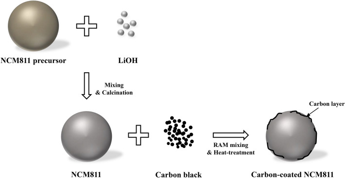
To prepare the NCM811, the Ni0.8Co0.1Mn0.1(OH)2 precursor was fabricated via a co-precipitation method. The solutions of NiSO4·6H2O, CoSO4·7H2O and MnSO4·H2O were used as starting materials. The NaOH and NH4OH solution were also used as chelating agent. As-prepared spherical Ni0.8Co0.1Mn0.1(OH)2 precursor was mixed with LiOH·H2O in a molar ratio of 1:1.05. Then, the mixed powders were calcined at 480 °C for 5 h and 750 °C for 15 h in air, as shown in Fig. 16. The powders were mixed with different amounts (SPB 0.1 wt%, SPB 0.3 wt%, SPB 0.5 wt% and SPB 0.7 wt%) of super-P carbon black via resonant acoustic mixer (PharmaRAM™ I, Resodyn Acoustic Mixers Inc.) at the acceleration of high mix for 20 min. and then calcined at 300 °C for 3 h.
Figure 1.
Schematic illustration of the synthesis process of carbon-coated NCM811.
The structural properties and morphologies of the cathodes were measured via X-ray diffraction (XRD, X-pert PRO MPD, Philips, Cu Kα), field emission scanning electron microscopy (FESEM, S-4800, HITACHI) and field emission transmission electron microscope (FETEM, Titan G2, FEI Company).
To measure the electrochemical performance, the cathodes were prepared using 96 wt% active materials, 2 wt% super-P and 2 wt% polyvinylidene fluoride (PVDF) binder. The prepared slurry was coated on Al foil (16 μm in thickness) and then dried at 100 °C for 10 h in a vacuum oven. The cathodes were punched into disks and then dried at 120 °C for 10 h. The 2032 coin cells were fabricated by pristine and carbon-coated NCM811 cathode and lithium (500 μm in thickness) anode. A polyethylene (PE, 20 μm in thickness) was employed as a separator and 1 M LiPF6 in a mixed solution containing ethylene carbonate (EC)/dimethyl carbonate (DMC)/ethylmethyl carbonate (EMC) (1:1:1, v/v/v) was used as electrolyte. The coin cells were assembled in an Ar-filled glove box6.
The charge–discharge performance was galvanostatically tested in the voltage range of 3.0–4.3 V and various current density using electrochemical equipment (TOSCAT-3100, Toyo system) at room temperature. Cyclic voltammetry (CV) of the samples was performed with multi potentiostat (VSP300, Bio-Logic) at a scan rate of 0.1 mV s−1. The electrochemical impedance spectroscopy (EIS) measurement was tested with a VSP300 impedance analyzer in the frequency range of 1 MHz–10 mHz with 5 mV amplitude6.
Results and discussion
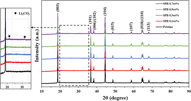
Figure 2 shows the XRD patterns of pristine and carbon-coated NCM811. All peaks are indexed based on a layered hexagonal α-NaFeO2 structure with the space group Rm22. The clear splitting of (006)/(102) and (018)/(110) peaks is observed in all samples, indicating well-ordered layered structure with small cation mixing23. However, the impurity phase Li2CO3, which is responsible for the deterioration of electrochemical properties, is observed for SPB 0.7 wt% NCM811. It can be explained by the large amount carbon sources can produce Li2CO3 by reacting with Li2O (lithium residuals), as the following equation24:
| 1 |
Figure 2.
XRD patterns of pristine and carbon-coated NCM811.
This phenomenon leads to excessive lithium impurities on the surface of NCM811 and is closely related to the crystallinity of the layered NCM811 structure. The intensity ratio of I(003)/I(104) means the degree of cation mixing between Li+ and Ni2+ in the Li layer due to the similar ionic radius of Li+ (0.76 Å) and Ni2+ (0.69 Å). A higher value the I(003)/I(104), the lower cation mixing. It was reported that I(003)/I(104) value less than 1.2 indicates undesirable cation mixing, resulting in poor electrochemical performances25,26. As summarized in Table 1, the I(003)/I(104) values are inversely proportional to the carbon content and SPB 0.7 wt% NCM811 shows the lowest value of 1.35. However, all samples deliver high I(003)/I(104) values, indicating excellent layered structures with high cation ordering. Therefore, it is clear that appropriate amount of carbon coating does not adversely affect the structure of NCM811.
Table 1.
The I003/I104 ratio of pristine and carbon-coated NCM811 samples.
| Pristine | 0.1 wt% | 0.3 wt% | 0.5 wt% | 0.7 wt% | |
|---|---|---|---|---|---|
| I003/I104 | 1.43 | 1.42 | 1.42 | 1.41 | 1.35 |
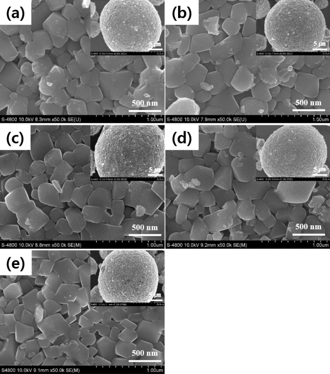
The microstructures of the pristine and carbon-coated NCM811 are shown in Fig. 3. The images show the micro-sized spherical secondary particles (15–20 µm), aggregated with primary particles of 200–500 nm. It is the typical shape of cathode powders by the co-precipitation method. There are no clear differences in the morphologies between the pristine and carbon-coated NCM811. The size of primary particles of all samples is almost similar regardless of carbon contents. Therefore, it can be inferred that the carbon coating does not affect the grain growth. The secondary particle with a porous structure has high specific surface areas and pore volumes between primary particles, resulting in improving the electrochemical performances by excellent electrolyte wettability of NCM811.
Figure 3.
FESEM images of pristine and carbon-coated NCM811: (a) pristine; (b) SPB 0.1 wt%; (c) SPB 0.3 wt%; (d) SPB 0.5 wt% and (e) SPB 0.7 wt%.
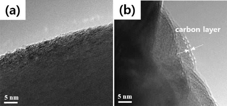
Figure 4 shows the FETEM images of the (a) pristine and (b) SPB 0.5 wt% NCM811 to identify the coating layers on the surface of NCM811. The pristine NCM811 shows the perfect crystallinity without amorphous layer on the surface of the NCM811, indicating no carbon layer. Comparatively, it is clear that SPB 0.5 wt% NCM811 exhibits amorphous carbon coating on the surface. The NCM811 was randomly coated with a carbon layer ranging from 0.89 to 1.23 nm. Hong et al. reported that it is not easy to form the uniform and ultrathin carbon layer due to weak adhesion27.
Figure 4.
FETEM images of (a) pristine and (b) SPB 0.5 wt% NCM811.
The electrochemical performances of the NCM811 cathode were measured in thick electrode laminates with high mass loading per area (approximately 15.1 mg/cm2) because the high areal capacity is the one of the most important factor for practical application. Also, the total weights of carbon-coated NCM811 include a carbon weight.
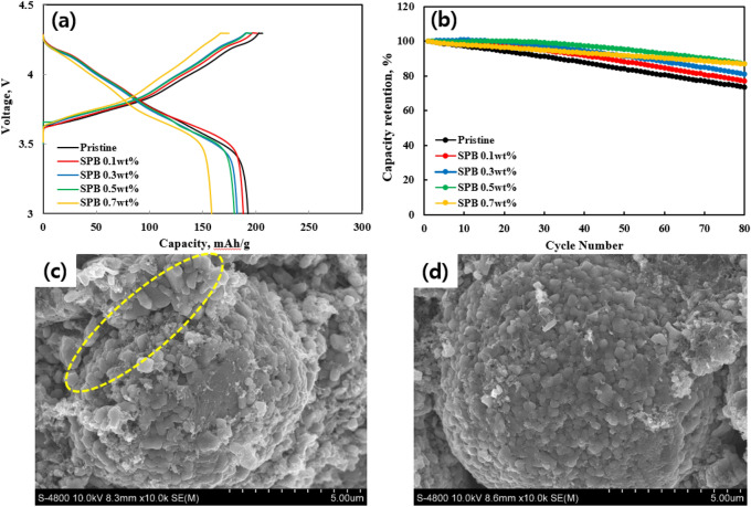
Figure 5 shows the (a) initial charge–discharge profiles and (b) cycling performances of pristine and carbon-coated NCM811 samples at the rate of 0.5 C (1 C = 202 mAh g−1) at 25 °C. The voltage plateaus correspond to the typical charge–discharge behavior of the Ni-rich layered NCM cathodes. The pristine NCM811 initially delivered a discharge capacity of 192.8 mAh g−1, while the discharge capacities of carbon-coated NCM811 slightly decrease. The SPB 0.1, 0.3, 0.5 and 0.7 wt% NCM811 exhibited the initial discharge capacities of 190.5, 189.1, 188.6 and 165.2 mAh g−1, respectively. This is because carbon coating layer serves as an obstacle because of higher electrode polarizations. It leads to inferior specific capacities compared to pristine NCM811. Among them, the capacity of SPB 0.7 wt% NCM811 drastically decreased due to holdback for the lithium ion transport by excessive thickness of the carbon layer.
Figure 5.
(a) Initial charge–discharge curves at 0.5 C and (b) cycle performance of pristine and carbon-coated NCM811. FESEM images of (c) pristine and (d) SPB 0.5 wt% NCM811 after 80 cycles.
Figure 5b shows the cycle performances of pristine and carbon-coated NCM811 samples after 80 cycles at 0.5 C. Obviously, the carbon coating helps to obtain a superior cycle stability of NCM811 compared to pristine NCM811. The capacity retentions of SPB 0.1, 0.3, 0.5 wt% NCM811 were 77.8, 81.9 and 87.8% after 80 cycles. The capacity retentions of SPB 0.1 and 0.3 wt% NCM811 were somewhat lower than those of SPB 0.5 wt% and 0.7 wt% NCM811. It can be explained by insufficient coating coverage on the NCM811 surface28. In addition, although the SPB 0.7 wt% NCM811 also exhibited excellent cyclability, it should be mentioned that the discharge capacity was too low compared to other samples, as mentioned above. Most importantly, it is clearly showed that the carbon-coated NCM811 shows stable cyclability than that of pristine NCM811. The pristine NCM811 had a capacity retention of 74.3% under the same condition. Among the carbon-coated NCM811, the SPB 0.5 wt% NCM811 can minimize the capacity fading due to the fast diffusion kinetics of lithium ions and electrons. Also, it can be attributed to the carbon coating, which suppresses the side reaction between NCM811 and electrolyte, resulting in structural degradation. More importantly, it is closely related to the gas generation, resulting from lattice oxygen, Li2CO3 and electrolyte decomposition29. (1) CO and CO2 are anodic oxidation product of EC and DMC solvent, which can be expressed as29:
| 2 |
| 3 |
(2) It is inevitable that Li2CO3 is formed which reacts with LiPF6 to generate POF3 and CO2 as shown in the following equation29:
| 4 |
In addition, the LiPF6 salt is spontaneously decomposed and generates gas as follows29:
| 5 |
| 6 |
| 7 |
Most importantly, carbon layer is expected to protect the NCM811 from attack by hydrogen fluoride (HF), dissolving the transition metal ions, thereby collapses the NCM811 structure. Therefore, carbon coating can effectively suppress the capacity decay and solve the safety problems (explosion and fires)30.
Figure 5c,d show the FESEM images of the pristine and SPB 0.5 wt% NCM811 after 80 cycles, indicating the effect of carbon coating for electrode stability. After cycling, the pristine and SPB 0.5 wt% NCM811 exhibited a clear difference. The pristine NCM811 showed separation of the primary particles from the secondary particles (marked by yellow circle). It is well known that Ni-rich layered NCM cathodes, especially x > 0.8, suffer from volume change during charge/discharge process, which creates external surface cracks and separation of primary particles. The external surface cracks gradually deteriorate the capacity by electrolyte attack and internal cracks31. However, the SPB 0.5 wt% NCM811 maintained its original shape with no significant damage, enabling superior electrochemical performances.
To further investigate the effect of the carbon coating on the NCM811/electrolyte interface resistance, the electrochemical impedance spectroscopy (EIS) was performed after 50 cycles (Fig. 6). The semicircle at the highest frequency is related to the resistance of solid electrolyte interface (RSEI), the high-to-medium frequency semicircle represent the charge transfer resistance at the interface between electrode and electrolyte (Rct), and a slope at low frequency corresponds to the Warburg impedance, related to the Li+ diffusion in the solid electrode30. According to the literature32, the impedance of the cell was mainly decided by the cathode impedance, especially for Rct. Moreover, the SPB 0.5 wt% NCM811 shows the lower Rct values than pristine NCM811, as shown in Table 2. It can be inferred that carbon layer can reduce the side reaction and maintain the original structure of well-ordered NCM811 structure, resulting in smooth and rapid lithium ion and electron transfer.
Figure 6.
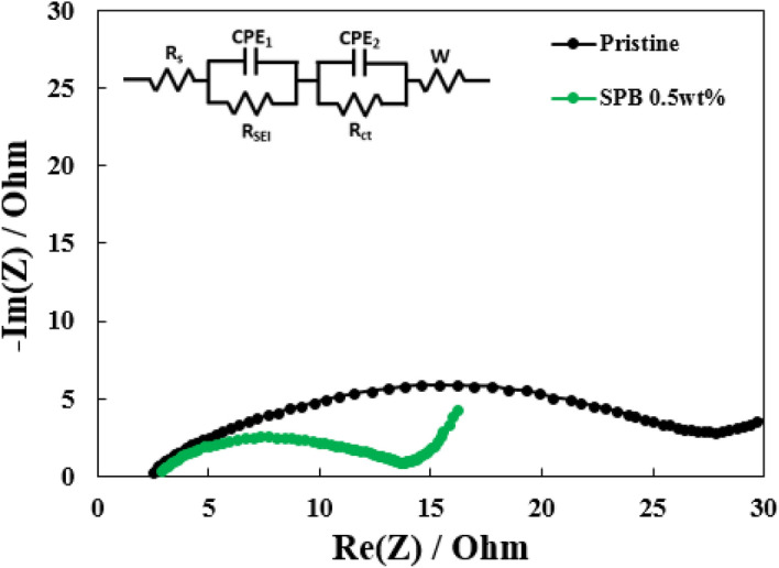
Nyquist plots of pristine and SPB 0.5 wt% NCM811 samples after 50 cycles.
Table 2.
The Rct values of pristine and carbon-coated NCM811 samples after 50 cycles.
| Rct [Ω] | |
|---|---|
| After cycling | |
| Pristine | 23.65 |
| SPB 0.5 wt% | 11.28 |
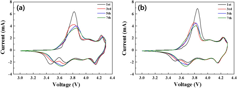
Figure 7a,b show the CV curves of pristine and SPB 0.5 wt% NCM811 samples after 1, 3, 5 and 7 cycles at a scan rate of 0.1 mV s−1. During the charge–discharge process, the pristine and SPB 0.5 wt% NCM811 had oxidation/reduction peaks at around 3.8 V and 4.23 V, which are corresponding to Ni2+/Ni4+ and Co3+/Co4+, respectively33,34. It can be seen that the position of the redox peak of the carbon coating is more stable than that of the pristine NCM81135. It demonstrates that carbon coating provides lower electrode polarization between anodic and cathodic peaks, enabling better reversibility during cycling36. These low Rct and polarization values of SPB 0.5 wt% NCM811 are the important reasons for superior capacity retention during long-term cycling.
Figure 7.
Cyclic voltammetry of (a) pristine and (b) SPB 0.5 wt% NCM811 in the voltage range of 3.0–4.3 V at a scan rate of 0.1 mV s−1.
Figure 8 shows the rate capability of the pristine and SPB 0.5 wt% NCM811. It is obvious that the retention decreases with the increasing C-rates. All samples showed comparable retentions up to 2 C. However, a significant difference is shown between the two samples at 5 C. The SPB 0.5 wt% NCM811 showed relatively higher retention (37.8 %) while the pristine NCM811 maintained lower retention of 30.9%. The superior capacity retention is attributed to the higher conductivity of SPB 0.5 wt% NCM811. Moreover, SPB 0.5 wt% NCM811 entirely recovered the capacity retention when the current density returned to 0.5 C, resulting from modification of NCM811 surface chemistry. It can be explained by the fact that a carbon coating layer of appropriate thickness inhibits negative effects, thereby improving structural stability and decreasing resistance. These enable quick lithium ion and electron migration29. Therefore, we can conclude that the carbon coating can improve the rate capability and reversibility, especially at the high rate. It is one of the most important factor for application to the high-power LIBs.
Figure 8.
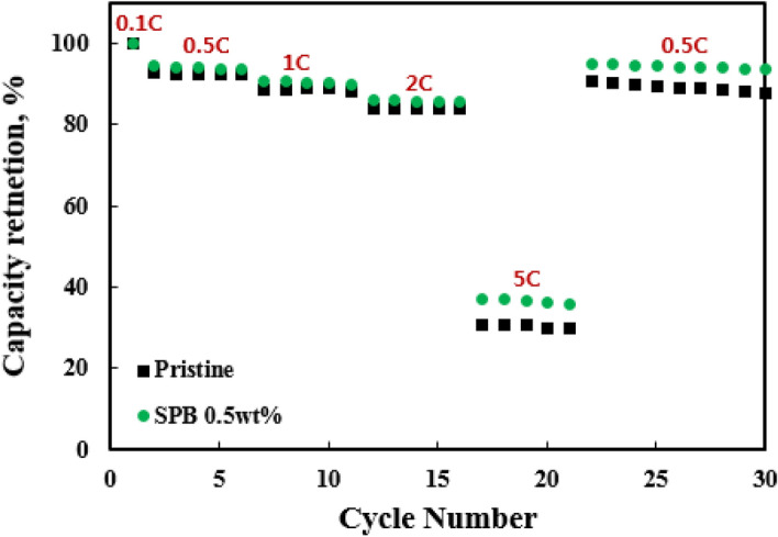
Rate capability of the pristine and SPB 0.5 wt% NCM811.
Conclusion
In this paper, we prepared pristine and carbon-coated NCM811 cathodes. The appropriate thickness of carbon layer effectively maintained the electrode stability and delivered better cyclability and rate capability than pristine NCM811. Among the carbon-coated NCM811, the SPB 0.5 wt% NCM811 had not only the original well-crystallized structure but also superior electrochemical performances. These can be explained by the dual roles of carbon coating, including (1) physical and chemical barrier and (2) increase in Li+ and electron conductivity. Based on these, the carbon coating is remarkable breakthrough to overcome the drawbacks of Ni-rich cathode.
Acknowledgements
This work was supported by the Development Program (10067187, Development of Design and Fabrication Technology of High-Ni Based Cathode Electrode with High Energy/Safety for EV Battery and 20007163, Development of localization technology for polymer binder core material process for midium to large type lithium ion battery positive electrode based on copolymer) funded by the ministry of Trade, Industry and Energy (MOTIE), Korea.
Author contributions
S.J.S. and S.H.L. wrote the main manuscript text. B.S.J. and S.H.L. carried out the fabrication of sample and interpretation of the results. B.S.J. and H.S.K. initiated the idea of working on the present topic. S.J.S. and H.S.K. analyzed all the experiments. All the authors read and approved the final manuscript.
Competing interests
The authors declare no competing interests.
Footnotes
Publisher's note
Springer Nature remains neutral with regard to jurisdictional claims in published maps and institutional affiliations.
These authors contributed equally: Seong-Ju Sim and Seung-Hwan Lee.
References
- 1.Myung ST, et al. Nickel-rich layered cathode materials for automotive lithium-ion batteries: achievements and perspectives. ACS Energy Lett. 2017;2:196–223. doi: 10.1021/acsenergylett.6b00594. [DOI] [Google Scholar]
- 2.Lee SH, et al. Recycling of Ni-rich Li(Ni0.8Co0.1Mn0.1)O2 cathode materials by a thermomechanical method. J. Alloys Compd. 2019;803:1032–1036. doi: 10.1016/j.jallcom.2019.06.229. [DOI] [Google Scholar]
- 3.Min K, et al. High-performance and industrially feasible Ni-rich layered cathode materials by integrating coherent interphase. ACS Appl. Mater. Interfaces. 2018;10:20599–20610. doi: 10.1021/acsami.8b05648. [DOI] [PubMed] [Google Scholar]
- 4.Song HJ, et al. Artificial cathode-electrolyte interphases on nickel-rich cathode materials modified by silyl functional group. J. Power Sources. 2019;416:1–8. doi: 10.1016/j.jpowsour.2019.01.050. [DOI] [Google Scholar]
- 5.Seok JW, et al. Effect of LiPO2F2 electrolyte additive on surface electrical properties of LiNi0.6Co0.2Mn0.2O2 cathode. Trans. Electr. Electron. Mater. 2019;20:548–553. doi: 10.1007/s42341-019-00151-5. [DOI] [Google Scholar]
- 6.Sim SJ, et al. Improving the electrochemical performances using a V-doped Ni-rich NCM cathode. Sci. Rep. 2019;9:8952. doi: 10.1038/s41598-019-45556-7. [DOI] [PMC free article] [PubMed] [Google Scholar]
- 7.Lee Y-S, et al. Improvement of the cycling performance and thermal stability of lithium-ion cells by double-layer coating of cathode materials with Al2O3 nanoparticles and conductive polymer. ACS Appl. Mater. Interfaces. 2015;7:13944–13951. doi: 10.1021/acsami.5b02690. [DOI] [PubMed] [Google Scholar]
- 8.Hu SK, et al. Cycle life improvement of ZrO2-coated spherical LiNi1/3Co1/3Mn1/3O2 cathode material for lithium ion batteries. J. Power Sources. 2009;188:564–569. doi: 10.1016/j.jpowsour.2008.11.113. [DOI] [Google Scholar]
- 9.Liu W, et al. Improvement of the high-temperature, high-voltage cycling performance of LiNi0.5Co0.2Mn0.3O2 cathode with TiO2 coating. J. Alloys Compd. 2012;543:181–188. doi: 10.1016/j.jallcom.2012.07.074. [DOI] [Google Scholar]
- 10.Lee SH, et al. Improved electrochemical performances of LiNi0.8Co0.1Mn0.1O2 cathode via SiO2 coating. J. Alloys Compd. 2019;791:193–199. doi: 10.1016/j.jallcom.2019.03.308. [DOI] [Google Scholar]
- 11.Zhao R, et al. Improving the Ni-rich LiNi0.5Co0.2Mn0.3O2 cathode properties at high operating voltage by double coating layer of Al2O3 and AlPO4. J. Alloys Compd. 2017;724:1109–1116. doi: 10.1016/j.jallcom.2017.05.331. [DOI] [Google Scholar]
- 12.Lee SW, et al. Li3PO4 surface coating on Ni-rich LiNi0.6Co0.2Mn0.2O2 by a citric acid assisted sol–gel method: Improved thermal stability and high-voltage performance. J. Power Sources. 2017;360:206–214. doi: 10.1016/j.jpowsour.2017.05.042. [DOI] [Google Scholar]
- 13.Zheng JM, et al. The effects of AlF3 coating on the performance of Li[Li0.2Mn0.54Ni0.13Co0.13]O2 positive electrode material for lithium-ion battery. J. Electrochem. Soc. 2008;155:A775–A782. doi: 10.1149/1.2966694. [DOI] [Google Scholar]
- 14.Lee S, et al. Carbon-coated single-crystal LiMn2O4 nanoparticle clusters as cathode material for high-energy and high-power lithium-ion batteries. Angew. Chem. Int. Ed. 2012;51:8748–8752. doi: 10.1002/anie.201203581. [DOI] [PubMed] [Google Scholar]
- 15.Yang C, et al. Preparation and rate capability of carbon coated LiNi1/3Co1/3Mn1/3O2 as cathode material in lithium ion batteries. ACS Appl. Mater. Interfaces. 2017;9:12408–12415. doi: 10.1021/acsami.6b16741. [DOI] [PubMed] [Google Scholar]
- 16.Liu Z, et al. Three-dimensional ordered porous electrode materials for electrochemical energy storage. NPG Asia Mater. 2019;11:12. doi: 10.1038/s41427-019-0112-3. [DOI] [Google Scholar]
- 17.Son IH, et al. Graphene balls for lithium rechargeable batteries with fast charging and high volumetric energy densities. Nat. Commun. 2017;8:1561. doi: 10.1038/s41467-017-01823-7. [DOI] [PMC free article] [PubMed] [Google Scholar]
- 18.Chen KS, et al. Comprehensive enhancement of nanostructured lithium-ion battery cathode materials via conformal graphene dispersion. Nano Lett. 2017;17:2539–2546. doi: 10.1021/acs.nanolett.7b00274. [DOI] [PubMed] [Google Scholar]
- 19.Li H, et al. Enhancing the performances of Li-ion batteries by carbon-coating: present and future. Chem. Commun. 2012;48:1201–1217. doi: 10.1039/C1CC14764A. [DOI] [PubMed] [Google Scholar]
- 20.Kwon NH. The effect of carbon morphology on the LiCoO2 cathode of lithium ion batteries. Solid State Sci. 2013;21:59–65. doi: 10.1016/j.solidstatesciences.2013.04.010. [DOI] [Google Scholar]
- 21.Marcinek ML, et al. Microwave plasma chemical vapor deposition of carbon coatings on LiNi1/3Co1/3Mn1/3O2 for li-ion battery composite cathodes. J. Electrochem. Soc. 2009;156:A48–A51. doi: 10.1149/1.3021007. [DOI] [Google Scholar]
- 22.Lee KS, et al. Structural and electrochemical properties of layered Li[Ni1−2xCoxMnx]O2 (x=0.1–0.3) positive electrode materials for li-ion batteries. J. Electrochem. Soc. 2007;154:A971–A977. doi: 10.1149/1.2769831. [DOI] [Google Scholar]
- 23.Shaju KM, et al. Performance of layered Li(Ni1/3Co1/3Mn1/3)O2 as cathode for Li-ion batteries. Electrochim. Acta. 2002;48:145–151. doi: 10.1016/S0013-4686(02)00593-5. [DOI] [Google Scholar]
- 24.Ryu HH, et al. Capacity fading of Ni-rich Li[NixCoyMn1−x−y]O2 (0.6 ≤ x ≤ 0.95) cathodes for high energy density lithium-ion batteries: bulk or surface degradation? Chem. Mater. 2018;30:1155–1163. doi: 10.1021/acs.chemmater.7b05269. [DOI] [Google Scholar]
- 25.Ohzuku T, et al. Electrochemistry and structural chemistry of LiNiO2 (Rm) for 4 volt secondary lithium cells. J. Electrochem. Soc. 1993;140:1862–1870. doi: 10.1149/1.2220730. [DOI] [Google Scholar]
- 26.Wang GX, et al. Synthesis and characterization of LiNiO2 compounds as cathodes for rechargeable lithium batteries. J. Power Sources. 1998;76:141–146. doi: 10.1016/S0378-7753(98)00153-0. [DOI] [Google Scholar]
- 27.Hong S-A, et al. Toward uniform and ultrathin carbon layer coating on lithium iron phosphate using liquid carbon dioxide for enhanced electrochemical performance. J. Power Sources. 2014;262:219–223. doi: 10.1016/j.jpowsour.2014.03.132. [DOI] [Google Scholar]
- 28.Hildebrand S, et al. Al2O3, SiO2 and TiO2 as coatings for safer LiNi0.8Co0.15Al0.05O2 cathodes: electrochemical performance and thermal analysis by accelerating rate calorimetry. J. Electrochem. Soc. 2017;164:A2190–A2198. doi: 10.1149/2.0071712jes. [DOI] [Google Scholar]
- 29.Yoon JR, et al. Critical dual roles of carbon coating in H2Ti12O25 for cylindrical hybrid supercapacitors. Carbon. 2016;101:9–15. doi: 10.1016/j.carbon.2016.01.074. [DOI] [Google Scholar]
- 30.Lee SH, et al. Binder- and conductive additive-free laser-induced graphene/LiNi1/3Mn1/3Co1/3O2 for advanced hybrid supercapacitors. NPG Asia Mater. 2020;12:28. doi: 10.1038/s41427-020-0204-0. [DOI] [Google Scholar]
- 31.Lu H, et al. High capacity Li[Ni0.8Co0.1Mn0.1]O2 synthesized by sol–gel and co-precipitation methods as cathode materials for lithium-ion batteries. Solid State Ion. 2013;249–250:105–111. [Google Scholar]
- 32.Li J, et al. Study of the failure mechanisms of LiNi0.8Mn0.1Co0.1O2 cathode material for lithium ion batteries. J. Electrochem. Soc. 2015;162:A1401–A1408. doi: 10.1149/2.1011507jes. [DOI] [Google Scholar]
- 33.Noh H-J, et al. Comparison of the structural and electrochemical properties of layered Li[NixCoyMnz]O2 (x=1/3, 0.5, 0.6, 0.7, 0.8 and 0.85) cathode material for lithium-ion batteries. J. Power Sources. 2013;233:121–130. doi: 10.1016/j.jpowsour.2013.01.063. [DOI] [Google Scholar]
- 34.Li X, et al. Enhanced electrochemical performance of Zr-modified layered LiNi1/3Co1/3Mn1/3O2 cathode material for lithium-ion batteries. ChemElectroChem. 2016;3:130–137. doi: 10.1002/celc.201500360. [DOI] [Google Scholar]
- 35.Kondrakov AO, et al. Anisotropic lattice strain and mechanical degradation of high- and low-nickel NCM cathode materials for li-ion batteries. J. Phys. Chem. C. 2017;121:3286–3294. doi: 10.1021/acs.jpcc.6b12885. [DOI] [Google Scholar]
- 36.Schipper F, et al. Review-recent advances and remaining challenges for lithium ion battery cathodes. J. Electrochem. Soc. 2017;164:A6220–A6228. doi: 10.1149/2.0351701jes. [DOI] [Google Scholar]


