Abstract
Owing to their applications in biodetection and molecular bioimaging, near-infrared (NIR) fluorescent dyes are being extensively investigated. Most of the existing NIR dyes exhibit poor quantum yield, which hinders their translation to preclinical and clinical settings. Plasmonic nanostructures are known to act as tiny antennae for efficiently focusing the electromagnetic field into nanoscale volumes. The fluorescence emission from NIR dyes can be enhanced by more than thousand times by precisely placing them in proximity to gold nanorods. We have employed polyelectrolyte multilayers fabricated using layer-by-layer assembly as dielectric spacers for precisely tuning the distance between gold nanorods and NIR dyes. The aspect ratio of the gold nanorods was tuned to match the longitudinal localized surface plasmon resonance wavelength with the absorption maximum of the NIR dye to maximize the plasmonically enhanced fluorescence. The design criteria derived from this study lays the groundwork for ultrabright fluorescence bullets for in vitro and in vivo molecular bioimaging.
Keywords: dyes, fluorescence, gold nanorods, layer-by-layer technique, surface plasmon resonances
Fluorescence is a highly promising and rapidly emerging molecular imaging modality because of the high sensitivity, amenability to targeting, use of nonionizing radiation and nontoxic nature of the contrast agents.[1] Considering the nearly two order magnitude smaller endogenous absorption coefficient and minimal autofluorescence of tissue in the farred and near-infrared (NIR) parts of the electromagnetic spectrum (650–900 nm), NIR dyes are being extensively investigated for in vivo characterization of biological processes at the cellular and molecular levels. Over the past decade, there has been tremendous progress in the design and synthesis of novel NIR dyes that exhibit absorption and emission in the NIR window.[1a,c] However, the low quantum yield of most of these dyes limits their adoption into routine in vivo and clinical applications. Enhancing the brightness of NIR dyes will significantly improve the tissue imaging depth achieved with these molecular probes owing to the improved signal-to-noise ratio. In addition, the lower excitation power required for fluorescence imaging in vivo minimizes photobleaching and photo-thermal damage.
Recent reports demonstrate that the quantum efficiency of NIR dyes can be substantially improved by “lightning rod effect” of plasmonic nanostructures, often termed as plasmon-enhanced fluorescence (PEF).[2] The mechanism of PEF is relatively complex and it depends on intrinsic properties of plasmonic nanostructures (e.g., extinction, electromagnetic field distribution) and chromophore (e.g., absorption, transition states, and quantum yield), as illustrated by recent theoretical and experimental studies.[3] Although various reports experimentally demonstrate PEF, the design principles for achieving maximum fluorescence enhancement remain elusive.[3e,j,k,4] Systematically addressing various factors that influence the magnitude of PEF is critical for the design of ultrabright NIR imaging probes.
Here, we investigate the distance-dependent fluorescence enhancement using polyelectrolyte multilayers as dielectric spacers between NIR chromophores and plasmonic nanostructures (Figure 1A). Polyelectrolyte multilayers of poly-(allylamine hydrochloride) (PAH) and poly(styrene sulfonate) (PSS) were deposited using the immersion-based layer-by-layer (LbL) assembly method as reported previously.[5] We employ a low quantum yield (0.1) NIR dye, LS288,[6] as a model NIR chromophore and gold nanorods as plasmonic nanoantennae to probe the plasmon-enhanced fluorescence (PEF). Gold nanorods (AuNRs) offer a distinct advantage in that the localized surface plasmon resonance (LSPR) of AuNR can be tuned over a broad range, including the NIR wavelengths, by changing the aspect ratio of the AuNR.[7] The aspect ratio of the AuNR is chosen such that the longitudinal LSPR of the AuNR adsorbed on a glass slide overlapped with the absorption maxima of LS288 (Figure 1B). A representative TEM image shows the AuNR with a length of 63 ± 7.3 nm and a diameter of 14 ± 1.7 nm, making the aspect ratio about 4.5 (Figure 1C).
Figure 1.
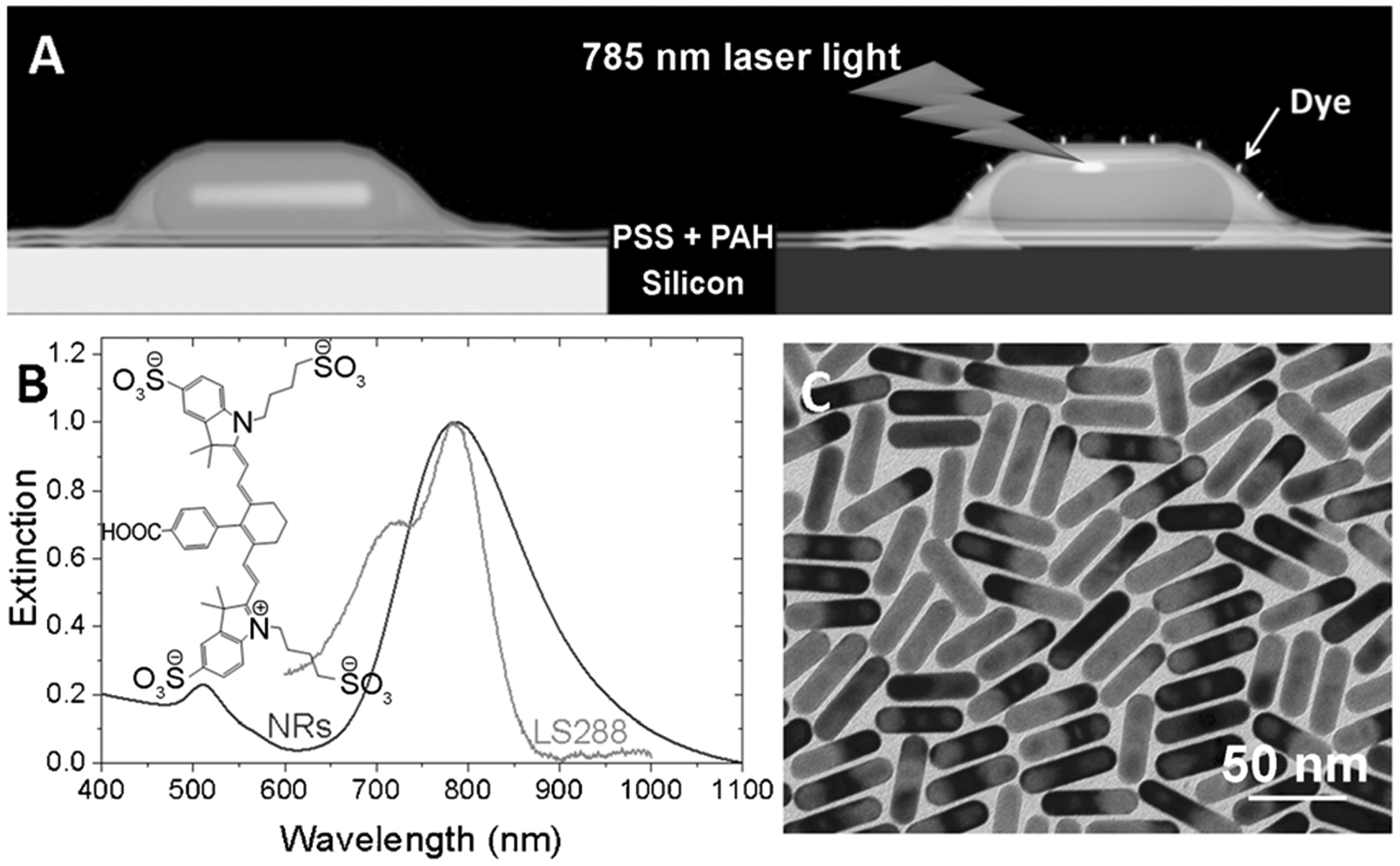
A) Polyelectrolyte multilayers obtained by layer-by-layer assembly to precisely place the dye molecule at a desired distance from the gold nanorods. B) Vis-NIR absorption and extinction properties of LS288 and gold nanorods, respectively. The absorption maxima of the dye overlaps with extinction spectra of gold nanorods with aspect ratio 4.5, which is important to obtain maximum fluorescence enhancement. C) Representative TEM image of the gold nanorods employed in this study.
AuNRs were chemisorbed on mercaptopropyltriethoxysilane (MPTES)-coated glass substrates. To avoid plasmon coupling, which results in broadening of the LSPR band, the density of the AuNR was limited to 29 ± 3 μm−2 (see the Experimental Section in the Supporting Information for details and Figure 3). Layer-by-layer assembly of PAH and PSS on the AuNR was performed by alternate immersion of the glass substrates into 1% polyelectrolyte (PSS and PAH) solutions in 0.1m NaCl.[5,8] Considering that AuNRs are positively charged, we initiate the multilayer deposition with negatively charged PSS and terminate with positively charged PAH, which facilitates the electrostatic adsorption of negatively charged LS288. Deposition of polyelectrolyte layers results in a progressive red shift and increase in the intensity of longitudinal LSPR of the AuNR owing to the increase in the effective refractive index of the medium around the AuNR (Figure 2A). Atomic force microscopy (AFM) at the edge of an intentional scratch (scratch test) confirmed the thickness of the polyelectrolyte layers (Figure 2B and Figure S3). The AFM height profile shows a thickness of about 20 nm after ten bilayers of PSS and PAH, indicating an average thickness of about 1 nm for each layer (inset in Figure 2B).
Figure 3.
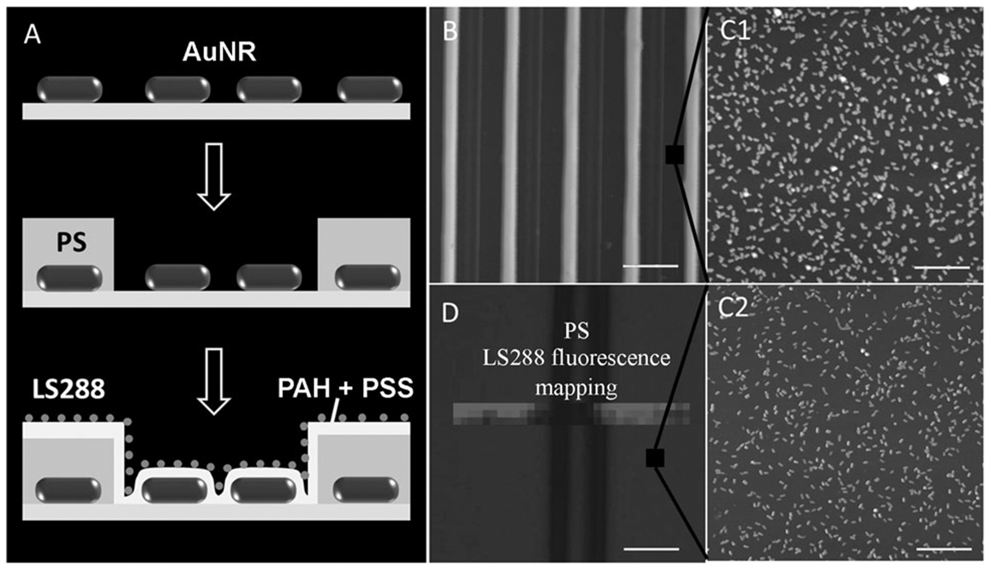
A) Capillary transfer lithography to ensure large separation between a AuNR and a dye. B) AFM images of poly(styrene) (PS) stripes on a glass substrate obtained by CTL; scale bar 10 μm. AFM images of AuNRs on a glass surface between PS stripes before (C1; no layers; scale bar 1 μm) and after (C2; four layers; scale bar 1 μm) deposition of two bilayers of PSS and PAH. D) Map of the fluorescence intensity from LS288 uniformly adsorbed on AuNRs and PS following the deposition of two bilayers of PSS and PAH; scale bar 5 μm.
Figure 2.
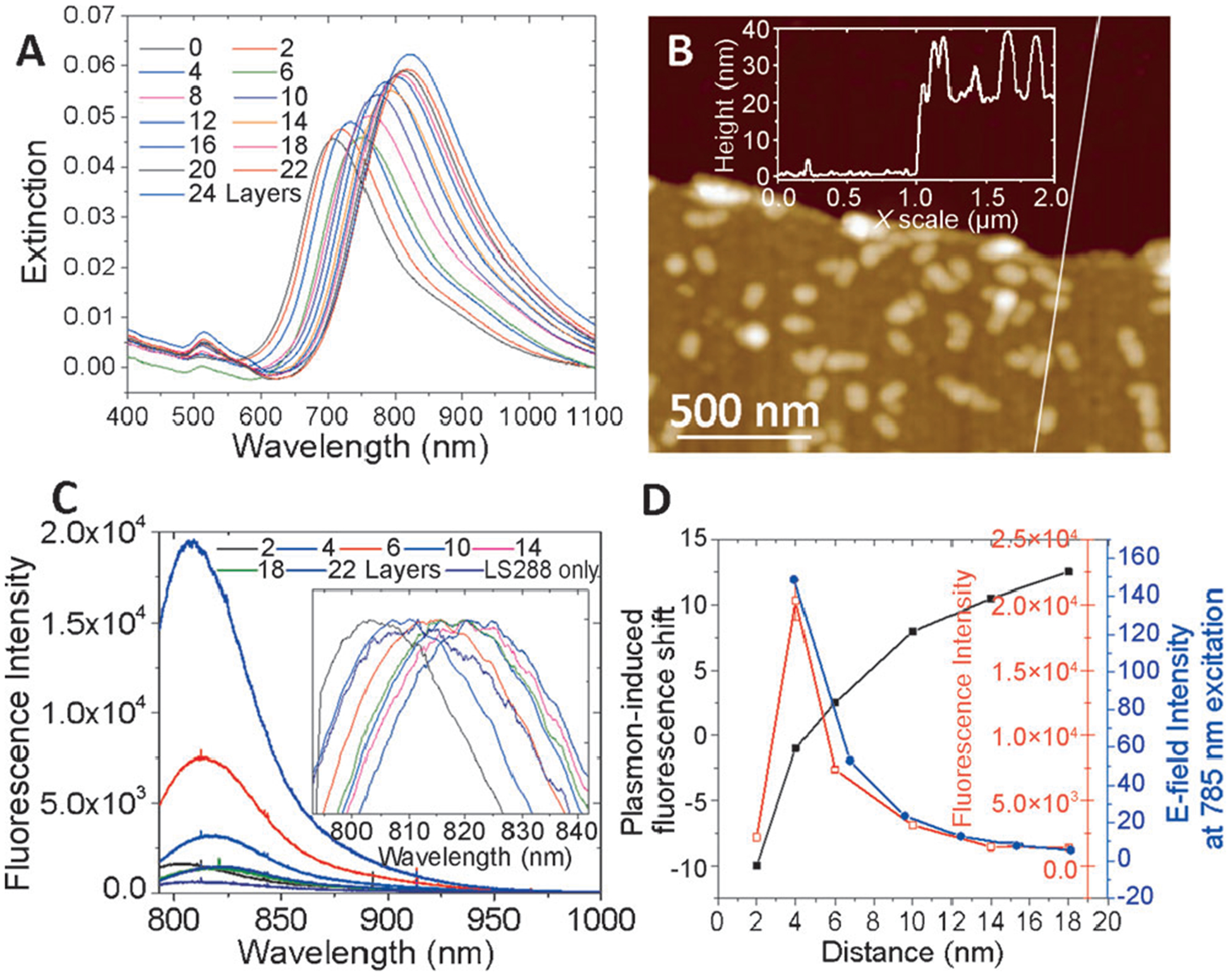
A) Vis-NIR extinction spectra of the AuNR coated with a different number of polyelectrolyte bilayers. B) AFM image along the edge of a scratch made in a film comprised of ten polyelectrolyte bilayers. (The inset shows the cross-section across the scratch.) C) Fluorescence intensity of LS288 deposited at different distances from the AuNR surface using polyelectrolyte bilayers as spacers. D) Plot correlating the distance from the AuNR surface to the fluorescence intensity and the enhanced electromagnetic field.
After deposition of the polyelectrolyte multilayers terminated with PAH, we electrostatically adsorb the LS288 dye from a dilute aqueous solution (1 μm) onto the polyelectrolyte surface followed by extensive rinsing to remove any weakly bound dye molecules. The uniformity of the dye adsorption on pristine glass slides was confirmed by mapping the fluorescence intensity with 1 μm step-size using a confocal fluorescence microscope. All fluorescence measurements were performed using 785 nm excitation at very low laser power (0.003 mW) to minimize photobleaching of LS288. The fluorescence map exhibited remarkable uniformity, confirming the uniform adsorption of the fluorophores on the PAH surface with no signs of patchiness (Figure S13). Distance-dependent PEF of LS288 was probed by adsorbing the fluorophores at different distances from the AuNR surface using 2, 4, 8, 12, 16, 20, and 24 polyelectrolyte layers as spacers (Figure 2C). The maximum fluorescence intensity was observed for a four layer spacer followed by a monotonic decrease in the fluorescence intensity with increase in the number of polyelectrolyte layers (Figure 2C and D). Finally, after 20 polyelectrolyte layers the fluorescence intensity equalled the intensity of the dye molecules on a PAH-coated glass substrate, indicating that the fluorophores placed at about 20 nm away from the AuNR surface are not significantly influenced by the enhanced electromagnetic (EM) field of the AuNR. With increase in the number of bilayers the fluorescence intensity decays exponentially similar to the EM field decay around the AuNR (Figure 2D).[5] These results suggest that spatial proximity of dye molecules and plasmonic nanostructures is critical to attain maximum PEF. However, when dye molecules are in direct contact or extremely close to AuNRs (about 2 nm), nonradiative energy transfer between the dye and AuNR leads to dramatic quenching of the fluorescence. The optimum distance between the dye and the AuNRs is found to be about 4 nm to obtain the maximum fluorescence enhancement (Figure 2D). Therefore, if the dye is too close or too far from the AuNRs, PEF is either diminished because of nonradiative energy transfer or a weak EM field, respectively.
To further demonstrate PEF of the NIR dye in proximity to a AuNR, we have employed soft lithography to form a microscale pattern of a AuNR on a glass surface (Figure 3A). Specifically, we employed capillary transfer lithography to form a pattern of 3 μm-wide polystyrene stripes interleaved with 7 μm-wide exposed regions of the AuNR chemisorbed on MPTES-coated glass substrates (Figure 3B). Subsequently, two polyelectrolyte bilayers were uniformly deposited over the entire surface followed by electrostatic adsorption of LS288 as described above (Figure 3C1 and C2). Fluorescence intensity mapping across the micropattern clearly shows the enhanced fluorescence from the AuNR regions compared to that from the polystyrene regions. The enhanced fluorescence from dye molecules spaced 4 nm away from the AuNR clearly demonstrates the PEF of the NIR dye (Figure 3D).
After probing the distance-dependent PEF phenomenon, we explored the relation between the optical properties of the components (that is, LSPR wavelength of plasmonic nanostructures and absorption and emission of the dye) and the magnitude of PEF. We used gold nanorods of three different aspect ratios for this study: 1 (AuNR 1), 2.3 (AuNR 2.3), and 4.5 (AuNR 4.5; Figure 4A–C). The aspect ratio enables facile tuning of the LSPR of the AuNR over a broad spectral range. In the present study, the LSPR wavelength of the three different AuNRs is at 540 (AuNR 1), 622 (AuNR 2.3), and 820 nm (AuNR 4.5; Figure 4D). Similar procedures described above were employed to chemisorb gold nanostructures on glass slides, deposit polyelectrolyte multilayers, and electrostatically adsorb monolayer of LS288. We fixed the dielectric spacer distance at 4 nm for all the nanostructures, which was found to be optimal for maximum PEF. We correlate the fluorescence intensities of LS288 with the extinction properties of all three nanostructures (Figure 4E). As expected, the PEF is primarily determined by the LSPR wavelength of the gold nanostructures. In the case of AuNR 1 (i.e., gold nanospheres), the LSPR wavelength is far from the excitation and emission maxima of LS288, resulting in no significant enhancement of fluorescence. Although the extinction maximum does not completely match with the absorption maximum of the dye, the nanorods with aspect ratio 2.3 generated an about 100 times higher fluorescence compared to the NPs. This enhanced fluorescence is possibly due to the partial overlap of the AuNR extinction with the dye absorption band. The maximum fluorescence enhancement was observed when the extinction maximum of the AuNR completely matched with the absorption maximum of the dye in AuNR 4.5. The extinction maximum of the AuNR matched with the dye emission after depositing four polyelectrolyte layers on which the dye is adsorbed. We employed finite-difference time-domain (FDTD) simulations to estimate the EM field enhancement at the surface of these nanostructures for 785 nm excitation used in this study. FDTD simulations reveal that the electric field intensity at the surface of AuNR 4.5 is nearly eight times higher than that of AuNR 2.3, which is in turn nine times higher than that of AuNR 1. Importantly, the PEF followed the same trend as the electric field intensity at the surface of these nanostructures at 785 nm excitation (Figure 4D–E).
Figure 4.
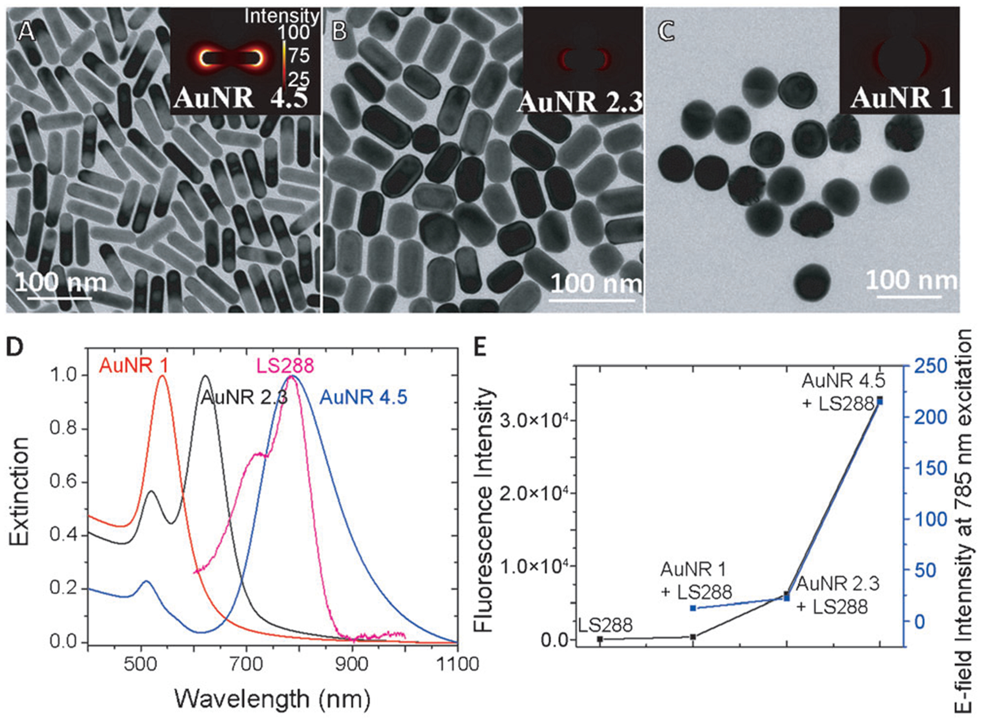
TEM images of nanorods with aspect ratios 4.5 (A), 2.3 (B), and nanoparticles (C). D) Vis-NIR extinction spectra of AuNR 1.0, AuNR 2.3, AuNR 4.5, and LS288 (D). E) Correlation of fluorescence intensity (black) of LS288 and electric field intensity (blue) for AuNR 4.5, AuNR 2.3, and AuNR 1.0.
While the above discussed results demonstrate the importance of the spectral proximity of AuNR LSPR wavelength and absorption maximum of the NIR dye, the spatial proximity of the dye molecules to the AuNR is also a critical factor. To demonstrate the importance of the spatial proximity, we chose the AuNR with longitudinal LSPR wavelength at 670 nm, which is about 110 nm lower than the absorption maximum of the dye. After the chemisorption of the AuNR on a glass substrate, dye molecules were adsorbed on the AuNR with ten polyelectrolyte layer spacer. As described above, deposition of polyelectrolyte layers resulted in a red shift of the LSPR wavelength of the AuNR to match the absorption maximum of the dye molecules. Although the absorption maximum of LS288 matches with the LSPR wavelength of the AuNR, the fluorescence enhancement was nearly ten times smaller than that observed for AuNR 4.5 with a 4 nm spacer.
Our experiments clearly reveal that the magnitude of PEF depends on the excitation wavelength, extinction, and emission of the dye, extinction of the AuNR, and the distance between the AuNR and the dye. We can deduce the following design criteria for maximum PEF: 1) the absorption maximum of the dye and extinction maxima of the metal nanostructures should have maximum overlap; 2) the emission maximum of the dye should also partially overlap with the extinction band of the AuNRs; and 3) the optimal distance (about 4 nm in our study using LS288) between dye molecules and plasmonic nanostructures is obtained by avoiding nonradiative energy transfer and ensuring a strong electromagnetic field.
The design principles derived from the substrate-bound AuNR are now applied to the AuNR dispersed in aqueous solution to achieve ultrabright NIR fluorescence bullets for bioimaging applications. The AuNRs were coated with polyelectrolyte bilayers followed by adsorption of NIR dyes at about 4 nm from the surface. We confirm the polyelectrolyte layers by measuring the zetapotential of the AuNRs after PSS and PAH coating. The charge reversal from positive charge of pristine AuNR to negative charge upon PSS coating and subsequent reversal to positive charge with PAH coating confirm the deposition of the polyelectrolyte coating on the AuNRs (Figure 5B). Dynamic light-scattering (DLS) measurements reveal a 4 nm increase in the hydrodynamic size after polyelectrolyte coating, which is the optimal distance between the AuNR and the dye for maximum fluorescence enhancement (Figure 5C). The fluorescence intensity from the NIR-dye-adsorbed AuNR was nearly three orders of magnitude higher compared to that obtained from a similar concentration of the free dye in solution (Figure 5D).
Figure 5.
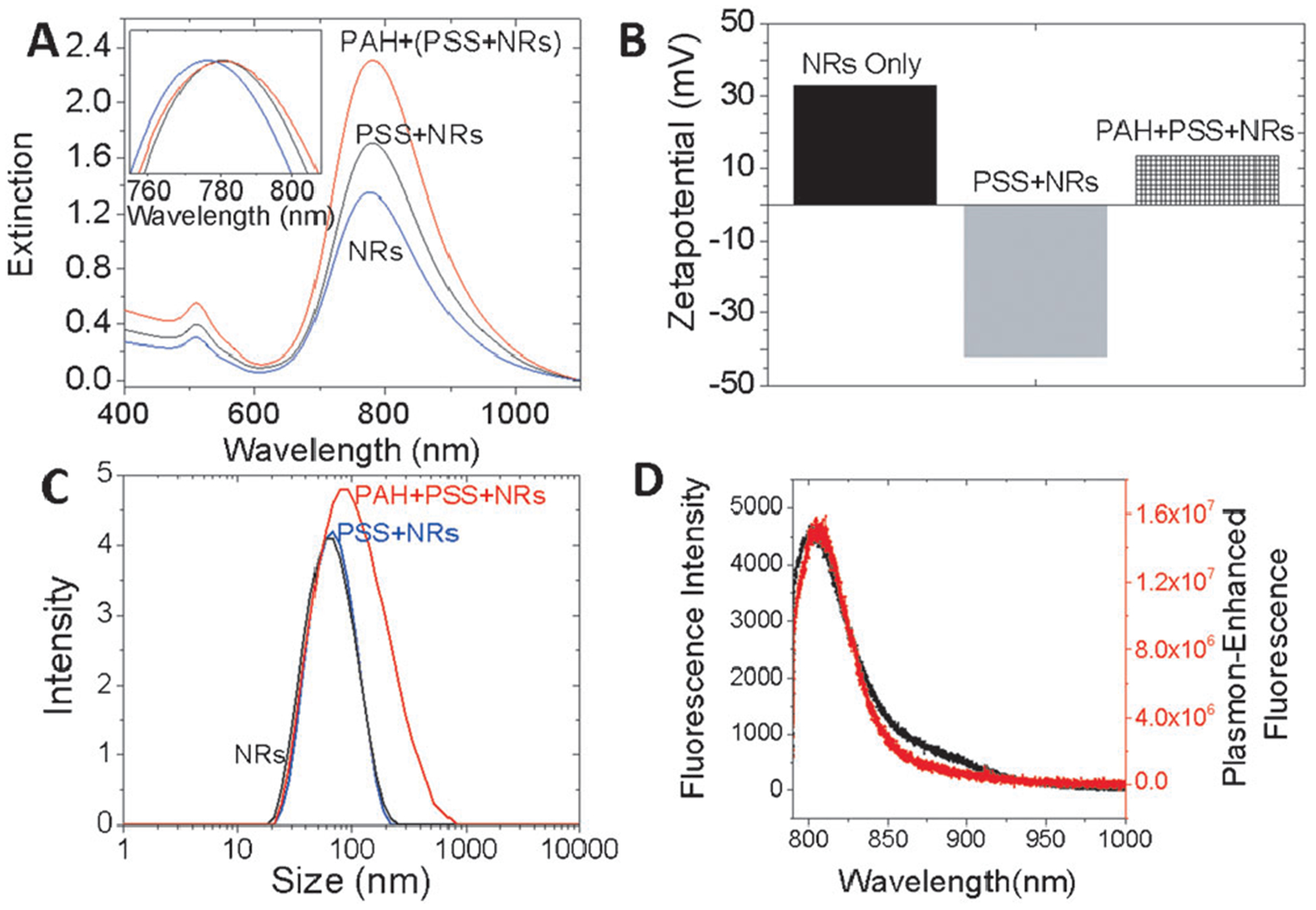
A) Vis-NIR extinction properties of AuNR, AuNR+PSS, and AuNR+PSS+PAH. B) Zeta potential and C) dynamic light scattering of AuNR, AuNR+PSS, and AuNR+PSS+PAH further confirm the successful coating of the AuNR with polyelectrolytes. D) Comparison of the LS288 fluorescence intensity between a free dye (black) and a dye adsorbed on polyelectrolyte-coated AuNRs (red).
We demonstrate the in vitro bioimaging efficacy of the ultrabright NIR fluorescence bullets using epithelial breast cancer cells (SKBR3). Three different nanostructures were chosen to demonstrate the bioimaging; AuNR 4.5, which was found to be optimal for LS288 and AuNR 2.3 and AuNR 1 as controls (Figure 6). In all cases, the dye was adsorbed at 4 nm from the surface. SKBR3 cells were incubated with 2 ngmL−1 of the AuNR followed by scanning confocal microscopy with 785 nm excitation. Consistent with the results discussed above, AuNR 1 and AuNR 2.3 exhibited a low fluorescence intensity. In contrast, AuNR 4.5 exhibited a very bright NIR fluorescence. To further confirm the enhanced bioimaging ability, we have performed flow cytometry measurements of cells incubated with a dye and dye-adsorbed AuNRs of three different aspect ratios. The quantification studies using flow cytometry shown in Figure 7 are consistent with confocal images in Figure 6. The fluorescence intensity from cells incubated with an optimal aspect ratio of the AuNR (about 4.5) is significantly higher compared to the dye and other AuNR samples. These results confirm that the design principles obtained from the substrate-bound AuNR could be successfully applied to achieve ultrabright fluorescence bullets and their application for in vitro bioimaging.
Figure 6.
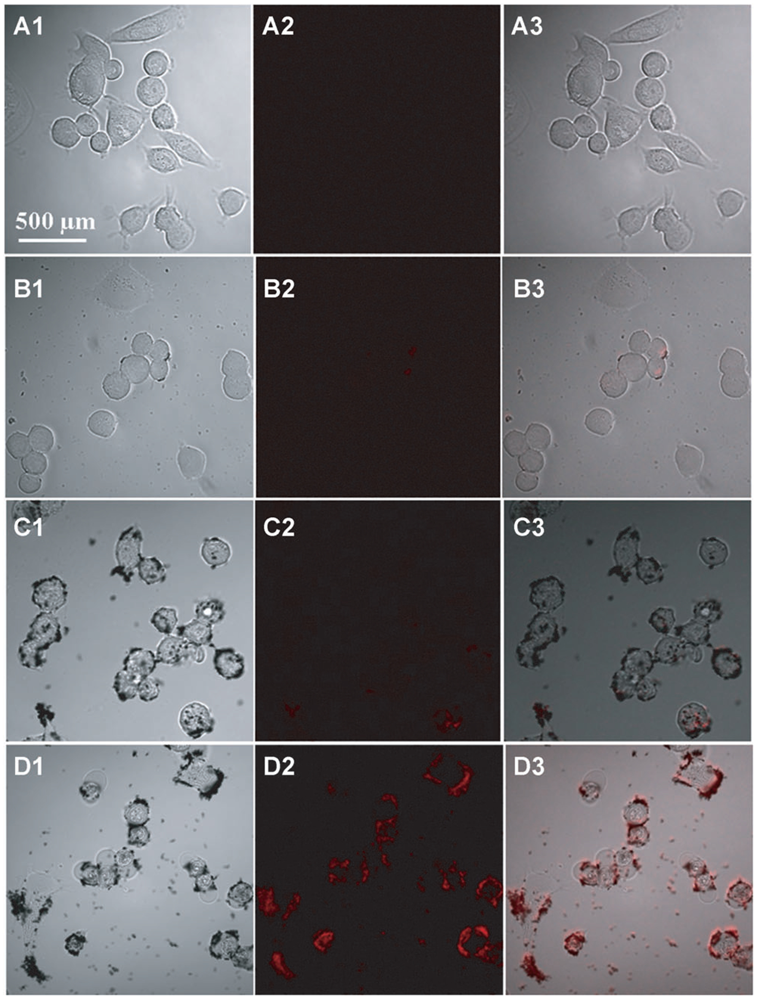
Confocal fluorescence microscopy images of passively targeted SKBR3 cells with LS288-adsorbed AuNR 1, AuNR 2, and AuNR 4 collected using 785 nm excitation. The columns 1, 2, and 3 are bright field, fluorescence, and merged images of SKBR3 cells, respectively. The microscopy images in rows A, B, C, and D correspond to the dye alone, AuNR 1, AuNR 2, and AuNR 4.5, respectively.
Figure 7.
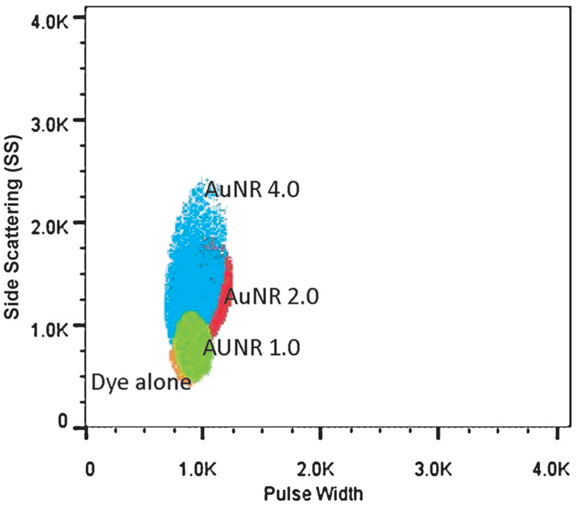
Flow cytometry of SKBR-3 (15000) cells incubated with a dye alone, AuNR 1.0+dye, and AuNR2+dye, and AuNR 4+dye. Cells incubated with AuNR 4 show a significantly higher fluorescence compared to those incubated with AuNR 1.0 and AuNR 2.
In summary, distance-dependent enhancement of fluorescence from dye molecules adsorbed on or in close proximity to plasmonic nanoantenna is investigated using LbL-assembled polyelectrolyte multilayers as dielectric spacers. A remarkable three order magnitude enhancement in fluorescence intensity was observed when the near infrared chromophores were spaced about 4 nm from the surface of gold nanorods employed as plasmonic nanoantennae. Increasing the dye-nanorod spacing resulted in a decay of plasmon enhanced fluorescence (PEF) that closely followed the decay of electric field intensity from the surface of the nanostructures. By precisely tuning the LSPR of the nanoantenna with respect to the absorption and emission of the dye, we demonstrate that significant overlap of the absorption and emission of the dye with plasmon extinction band of the plasmonic nanostructures is critical for large PEF observed here. Based on the design criteria, we demonstrate ultrabright NIR fluorescence bullets that enable significantly improved in vitro imaging of breast cancer cells. The design criteria established here can be readily extended to other NIR dyes by precise choice of plasmonic nanostructures and spacing. We expect that these findings will expedite the transition of novel NIR dyes to routine in vitro and in vivo applications.
Supplementary Material
Acknowledgments
We acknowledge financial support from the BRIGHT institute at Washington University under P50 Pilot Project Program and the National Science Foundation (grant number CBET-1254399). The authors thank Nano Research Facility (NRF), a member of the National Nanotechnology Infrastructure Network (NNIN), for providing access to electron microscopy facilities.
Footnotes
Supporting information for this article is available on the WWW under http://dx.doi.org/10.1002/anie.201308516.
Contributor Information
Naveen Gandra, Department of Mechanical Engineering and Materials Science, Washington University in St. Louis, 1 Brooking Drive, St. Louis, MO 63130 (USA).
Christopher Portz, Department of Mechanical Engineering and Materials Science, Washington University in St. Louis, 1 Brooking Drive, St. Louis, MO 63130 (USA).
Limei Tian, Department of Mechanical Engineering and Materials Science, Washington University in St. Louis, 1 Brooking Drive, St. Louis, MO 63130 (USA).
Rui Tang, Department of Radialogy, Washington University School of Medicine, St. Louis, MO 63110 (USA).
Baogang Xu, Department of Radialogy, Washington University School of Medicine, St. Louis, MO 63110 (USA).
Samuel Achilefu, Department of Radialogy, Washington University School of Medicine, St. Louis, MO 63110 (USA).
Srikanth Singamaneni, Department of Mechanical Engineering and Materials Science, Washington University in St. Louis, 1 Brooking Drive, St. Louis, MO 63130 (USA).
References
- [1].a) Achilefu S, Dorshow RB, Bugaj JE, Rajagopalan R, Invest. Radiol 2000, 35, 479; [DOI] [PubMed] [Google Scholar]; b) Chen X, Conti PS, Moats RA, Cancer Res. 2004, 64, 8009; [DOI] [PubMed] [Google Scholar]; c) Hilderbrand SA, Weissleder R, Curr. Opin. Chem. Biol 2010, 14, 71; [DOI] [PubMed] [Google Scholar]; d) Lee S, Vinegoni C, Feruglio PF, Fexon L, Gorbatov R, Pivoravov M, Sbarbati A, Nahrendorf M, Weissleder R, Nat. Commun 2012, 3, 2060. [DOI] [PMC free article] [PubMed] [Google Scholar]
- [2].a) Tam F, Goodrich GP, Johnson BR, Halas NJ, Nano Lett. 2007, 7, 496; [DOI] [PubMed] [Google Scholar]; b) Bardhan R, Grady NK, Cole JR, Joshi A, Halas NJ, ACS Nano 2009, 3, 744. [DOI] [PubMed] [Google Scholar]
- [3].a) Chi YS, Byon HR, Lee BS, Kong B, Choi HC, Choi IS, Adv. Funct. Mater 2008, 18, 3395; [Google Scholar]; b) Fu Y, Zhang J, Lakowicz JR, J. Am. Chem. Soc 2010, 132, 5540; [DOI] [PMC free article] [PubMed] [Google Scholar]; c) Leong K, Zin MT, Ma H, Sarikaya M, Huang F, Jen AKY, ACS Appl. Mater. Interfaces 2010, 2, 3153; [DOI] [PubMed] [Google Scholar]; d) Jiang Y, Wang H-Y, Wang H, Gao B-R, Hao Y.-w., Jin Y, Chen Q-D, Sun H-B, J. Phys. Chem. C 2011, 115, 12636; [Google Scholar]; e) Kang K, Wang J, Jasinski J, Achilefu S, J. Nanobiotechnol 2011, 9, 16; [DOI] [PMC free article] [PubMed] [Google Scholar]; f) Kern AM, Martin OJF, Nano Lett. 2011, 11, 482; [DOI] [PubMed] [Google Scholar]; g) Ming T, Chen H, Jiang R, Li Q, Wang J, J. Phys. Chem. lett 2011, 2, 191; [Google Scholar]; h) Zhao L, Ming T, Chen H, Liang Y, Wang J, Nanoscale 2011, 3, 3849; [DOI] [PubMed] [Google Scholar]; i) Kern AM, Meixner AJ, Martin OJF, ACS Nano 2012, 6, 9828; [DOI] [PubMed] [Google Scholar]; j) Liaw J-W, Tsai H-Y, Huang C-H, Plasmonics 2012, 7, 543; [Google Scholar]; k) Lisunova M, Mahmoud M, Holland N, Combs ZA, El-Sayed MA, Tsukruk VV, J. Mater. Chem 2012, 22, 16745; [Google Scholar]; l) Zhang T, Lu G, Li W, Liu J, Hou L, Perriat P, Martini M, Tillement O, Gong Q, J. Phys. Chem. C 2012, 116, 8804; [Google Scholar]; m) Liu S-Y, Huang L, Li J-F, Wang C, Li Q, Xu H-X, Guo H-L, Meng Z-M, Shi Z, Li Z-Y, J. Phys. Chem. C 2013, 117, 10636. [Google Scholar]
- [4].a) Ishida A, Majima T, Analyst 2000, 125, 535; [Google Scholar]; b) Dulkeith E, Morteani AC, Niedereichholz T, Klar TA, Feldmann J, Levi SA, van Veggel FCJM, Reinhoudt DN, Mçller M, Gittins DI, Phys. Rev. Lett 2002, 89, 203002; [DOI] [PubMed] [Google Scholar]; c) Schneider G, Decher G, Nerambourg N, Praho R, Werts MHV, Blanchard-Desce M, Nano Lett. 2006, 6, 530; [DOI] [PubMed] [Google Scholar]; d) Yuan H, Khatua S, Zijlstra P, Yorulmaz M, Orrit M, Angew. Chem 2013, 125, 1255; Angew. Chem. Int. Ed. 2013, 52, 1217. [DOI] [PubMed] [Google Scholar]
- [5].Tian L, Chen E, Gandra N, Abbas A, Singamaneni S, Langmuir 2012, 28, 17435. [DOI] [PubMed] [Google Scholar]
- [6].Lee H, Mason JC, Achilefu S, J. Org. Chem 2006, 71, 7862. [DOI] [PubMed] [Google Scholar]
- [7].a) Nikoobakht B, El-Sayed MA, Chem. Mater 2003, 15, 1957; [Google Scholar]; b) Lohse SE, Eller JR, Sivapalan ST, Plews MR, Murphy CJ, ACS Nano 2013, 7, 4135. [DOI] [PubMed] [Google Scholar]
- [8].Kedem O, Tesler AB, Vaskevich A, Rubinstein I, ACS Nano 2011, 5, 748. [DOI] [PubMed] [Google Scholar]
- [9].a) Wu H-L, Kuo C-H, Huang MH, Langmuir 2010, 26, 12307; [DOI] [PubMed] [Google Scholar]; b) Sisco PN, Murphy CJ, J. Phys. Chem. A 2009, 113, 3973. [DOI] [PubMed] [Google Scholar]
- [10].a) McConney ME, Singamaneni S, Tsukruk VV, Polym. Rev 2010, 50, 235; [Google Scholar]; b) Tsukruk VV, Singamaneni S, Scanning Probe Microscopy of Soft Matter: Fundamentals and Practices, Wiley-VCH, Weinheim, 2011. [Google Scholar]
Associated Data
This section collects any data citations, data availability statements, or supplementary materials included in this article.


