

Abstract
In this article, we show a flow-based programming environment for interactive geometry software. Flow-based programming is one of the programming paradigms. All of the processes and data are represented as nodes, and we connect processes and data with edges. We call the figure with nodes and edges graph because the figure looks like a planar graph.
There is a lot of software implementing flow-based programming. However, there are few mathematical software based on a flow-based programming environment. So, we develop experimental interactive geometry software to generate kaleidoscope patterns based on flow-based programming.
The software shows us some advantages of flow-based programming. First, it is easy to understand the procedure of construction. Second, flow-based programming is flexible. Third, flow-based programming has high extensibility. We seek possibilities of practical use of the geometrical construction software with flow-based programming.
Keywords: Flow-based programming, Interactive geometry software, Kaleidoscope patterns
Introduction
In this article, we show interactive geometry software with flow-based programming. Interactive geometry software is software that creates geometrical constructions, and we can manipulate geometrical objects by hand keeping relationships between the geometrical objects. For example, see Fig. 1. There are three points, and they form three lines. When we move one of the points, the lines are also moved according to the positions of points. One of the most famous interactive geometry software is GeoGebra.
Fig. 1.
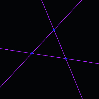
Three points and three lines
Flow-based programming is one of the programming paradigms. See Fig. 2. All processes and data are represented as nodes. We connect sockets of nodes with edges. We also call the resulting figure graph because the figure looks like a planar graph. In Fig. 2, there are three Point nodes, and they are connected to the three LineTwoPoints nodes by edges. The data is sent left to right through the edges. The geometrical objects are rendered as in Fig. 1.
Fig. 2.
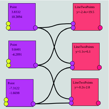
Nodes and edges
Flow-based programming is often used for creative coding or algorithmic design environments. For example, Max/MSP, PureData, vvvv, TouchDesigner, Grasshopper for Rhinoceros, and shader node graph editor implemented in three-dimensional modeling software like Blender or Maya. However, there is few mathematical software adopting a flow-based programming environment. We guess flow-based programming is suited for geometrical construction, that is, interactive geometry software. There are three advantages of flow-based programming. They are shown in the summary part.
The first author is developing an experimental interactive geometry software based on flow-based programming. The software also can draw kaleidoscope patterns. The name of the software is Flower. Flower is web application developed by JavaScript. It is published on the web site of the first author1. Also, we have an introductory video on YouTube2. It introduces basic operations of Flower.
Implementation
Flower is shown in Fig. 3. In Fig. 3, the left panel is a node graph editor. There are two Point nodes and one LineTwoPoints node. The right panel shows geometrical construction based on the graph. In Fig. 3, the Point nodes represent points, and a line passes through the points. They are rendered in the right panel. Also, we can move the point by mouse dragging. Then, the line is also moved according to the positions of points.
Fig. 3.

Point and LineTwoPoints nodes generating a line
All processes and data are represented as nodes and edges. The flows of data are represented by edges. We can find a procedure of construction from the node graph.
A LineMirror node receives a line and generates half-plane. In the graph of Fig. 4, all of the LineTwoPoints nodes are connected to LineMirror nodes. A kaleidoscope pattern generated by three half-planes is shown in the right panel of Fig. 4. Three half-planes are reflected in each other and filling all of the planes with triangles. Also, the image of a cat is repeatedly reflected.
Fig. 4.

Kaleidoscope pattern generated by half-planes
In this software, to generate a kaleidoscope pattern, not only half-planes, but we also use reflections by circles. It is also called inversion in circles. The equation is as follows. Let C be the center of the circle and let R be the radius of the circle. Inversion map of the circle is  in the complex coordinate. Figure 5 shows the image of the cat and its inverted image. Circle inversion transforms a circle as a circle, but other images are inverted with distortion.
Fig. 5.

Reflections of circles
Figure 6 shows a kaleidoscope pattern generated by inversions in four circles. The cats and circles are transformed infinitely repeated reflections by circles. So, it may take much time to render Fig. 6 because the number of circles and cats exponentially increases in the process of the reflections. So, we use our original algorithm called Iterated Inversion System (IIS) to render the right panel in Fig. 6.
Fig. 6.

Kaleidoscope pattern generated by circles
IIS is simple. For each point in the canvas, if the point is in the circle or half-plane, we apply a reflection of the geometrical object. We continue iterating the reflections until the point transformed outside of all of the objects. Finally, we determine color according to the number of reflections or refer to the pixel value of the iterated point. We can parallelize this algorithm easily. So, the figures are rendered in real-time when we use parallel processing. For more details, read [1] or [2].
We obtain this kind of fractal patterns in Fig. 7. It is generated by reflections of three half-planes and one circle. It is also rendered with IIS in real-time.
Fig. 7.

Fractal patterns generated by inversions in half-planes and a circle
Next, we show technical details about Flower. The left panel is rendered by Canvas 2D Context of html5. On the other hand, We have to use parallel processing to render images of the right panel in real-time with IIS. So, Flower uses fragment shader of OpenGL Shading Language (GLSL) on WebGL. From graph of the left panel, shader code to render geometrical components and kaleidoscope patterns is generated by template engine and compiled by WebGL. The positions of geometrical components are operated by uniform variables of the shader in the every frame.
Originally fragment shader is used to shade polygon model. However, in this case, we prepare rectangle composed of two triangles cover the screen. Then fragment shader determines the colors of screen pixel by pixel. For more details about this kind of shader graphics technique, read The Book of Shaders3 by Patricio Gonzalez Vivo and Jen Lowe.
Summary and Future Work
There are some advantages to adopting flow-based programming. Firstly, we can understand the procedure of constructions easily. We understand the relationships between mathematical components from the graph. Secondly, flow-based programming is flexible. We can insert processes wherever we like. For example, see Fig. 8. We can use a time-series data node such as SinWave node. It is connected to the y-coordinate socket of the Point node, and the point moves according to sin wave. Thirdly, flow-based programming has high extensibility. The users of the software can make their own node or script by their ideas, and add or extend functions of the software easily.
Fig. 8.

Sin wave node connected to the y-coordinate of the Point node
In this system, we only construct kaleidoscope patterns. Software with flow-based has prominent features. We aim to develop not only kaleidoscope pattern editor but also general-purpose geometrical construction software. We pursue the possibility of flow-based programming and interactive geometry software.
Footnotes
Contributor Information
Anna Maria Bigatti, Email: bigatti@dima.unige.it.
Jacques Carette, Email: carette@mcmaster.ca.
James H. Davenport, Email: j.h.davenport@bath.ac.uk
Michael Joswig, Email: joswig@math.tu-berlin.de.
Timo de Wolff, Email: t.de-wolff@tu-braunschweig.de.
Kento Nakamura, Email: somaarcr@gmail.com, https://soma-arc.net.
Kazushi Ahara, Email: ahara@meiji.ac.jp, https://aharalab.sakura.ne.jp.
References
- 1.Nakamura, K., Ahara, K.: A new algorithm for rendering kissing Schottky groups. In: Proceedings of Bridges 2016: Mathematics, Music, Art, Architecture, Education, Culture, pp. 367–370. Tessellations Publishing, Phoenix (2016)
- 2.Nakamura, K., Ahara, K.: A geometrical representation and visualization of Möbius transformation groups. In: Proceedings of Bridges 2017: Mathematics, Music, Art, Architecture, Education, Culture, pp. 159–166. Tessellations Publishing, Phoenix (2017)