

Abstract

Nitrogenase is the only enzyme that can cleave the strong triple bond in N2. The active site contains a complicated MoFe7S9C cluster. It is believed that it needs to accept four protons and electrons, forming the E4 state, before it can bind N2. However, there is no consensus on the atomic structure of the E4 state. Experimental studies indicate that it should contain two hydride ions bridging two pairs of Fe ions, and it has been suggested that both hydride ions as well as the two protons bind on the same face of the cluster. On the other hand, density functional theory (DFT) studies have indicated that it is energetically more favorable with either three hydride ions or with a triply protonated carbide ion, depending on the DFT functional. We have performed a systematic combined quantum mechanical and molecular mechanical (QM/MM) study of possible E4 states with two bridging hydride ions. Our calculations suggest that the most favorable structure has hydride ions bridging the Fe2/6 and Fe3/7 ion pairs. In fact, such structures are 14 kJ/mol more stable than structures with three hydride ions, showing that pure DFT functionals give energetically most favorable structures in agreement with experiments. An important reason for this finding is that we have identified a new type of broken-symmetry state that involves only two Fe ions with minority spin, in contrast to the previously studied states with three Fe ions with minority spin. The energetically best structures have the two hydride ions on different faces of the FeMo cluster, whereas better agreement with ENDOR data is obtained if they are on the same face; such structures are only 6–22 kJ/mol less stable.
Introduction
Nitrogenase (EC 1.18/19.6.1) is the only enzyme that can cleave the triple bond of N2, forming two molecules of ammonia and making atmospheric nitrogen available for biological systems.1−3 Nitrogenase is found only in some bacteria and cyanobacteria, but several higher plants, e.g. legumes, rice, and alder, live in symbiosis with such microorganisms. Nitrogenase consists of two proteins, the Fe protein that delivers electrons and the MoFe protein that contains the active site. Crystallographic studies have shown that the Fe protein contains a Fe4S4 cluster, whereas the MoFe protein contains the Fe8S7Cys6 P-cluster, used for electron transfer, and the catalytic MoFe7S9C(homocitrate)CysHis FeMo cluster (shown in Figure 1).4−8 Alternative nitrogenases exist, in which the Mo ion is replaced by V or Fe.9
Figure 1.

Active site of nitrogenase, showing the QM system employed in our calculations, as well as the residue names, following the 3U7Q crystal structure.6
Nitrogenases catalyze the chemical reaction
| 1 |
The binding of two molecules of ATP triggers the binding of the reduced Fe protein to the MoFe protein and the delivery of one electron to the FeMo cluster.1−3 Then, both ATP molecules are hydrolyzed, and the Fe protein dissociates. This is repeated eight times during the catalytic cycle. Consequently, the reaction mechanism of nitrogenase is normally described by nine intermediates, E0–E8, differing in the number of delivered electrons, the Lowe–Thorneley cycle.10 E0 is the resting state, which is in the MoIII Fe3II Fe4 oxidation state.11−14 It is currently believed that four electrons and protons need to be added to E0, i.e., forming the E4 state, before N2 may bind.1−3,12,15 N2 binding is facilitated by the reductive elimination of H2, which would explain why H2 is a necessary byproduct of the reaction.3
Many computational studies of nitrogenase have been presented, with the hope to give a detailed atomistic description of the various reaction steps.3,12,23−28,13,16−22 Unfortunately, they have given strongly divergent results. For example, some studies have suggested that N2 is protonated alternatively on both N atoms, giving diazene (HNNH) and hydrazine (H2NNH2) as intermediates,24,27 whereas others have suggested that the distal N atom is first triply protonated and dissociates as NH3 before the second N atom is protonated.25,26 Likewise, some studies have suggested that N2 binds end-on to one24 or two Fe ions,25,28 whereas others have suggested that it binds side-on to two Fe ions28 or that it forms a covalent bond with the central carbide ion.26,27
In fact, there is not any consensus regarding the structure of the central E4 intermediate that binds N2. It should contain four protons, and Hoffman and co-workers have suggested, based on ENDOR experiments, that two of these bind to sulfide ions, whereas the other two bridge between two pairs of Fe ions as hydride ions.3,29,30 With the help of density functional theory (DFT) calculations, they have suggested a structure in which both hydride ions and the two protons bind on the same face of the cluster, viz., between the Fe2/6 and Fe3/7 pairs, as well as on the belt S2B and S5A ions, as is shown in Figure 2 (the name of the Fe and S ions, taken from the crystal structure,6 are also shown in the figure).28,30 On the other hand, Siegbahn has argued that it is energetically much more favorable if the protons bind to the central carbide, so that the most stable structure with four electrons and protons has one proton on a sulfide ion and three on the carbide, forming CH3 which moves out from the center of the cluster (giving rise to a cavity where N2 can subsequently bind).13,31,32
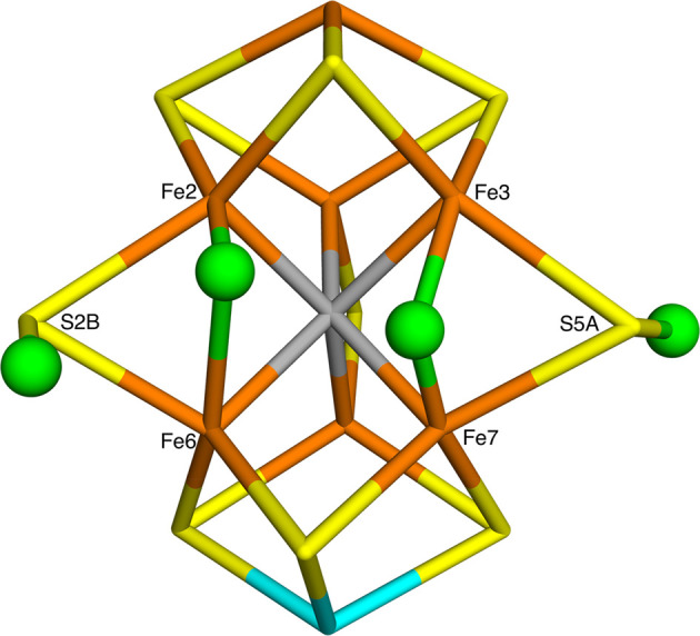
Figure 2.

Structure of E4 suggested by Hoffman and co-workers,3,28 as obtained by our QM/MM geometry optimizations. The protons (shown as green balls) bind to the S2B and S5A ions, whereas the hydride ions (also green balls) bridge the Fe2/6 and Fe3/7 pairs. It represents the S2B(5)–S5A(2)–Fe2/6(5)–Fe3/7(2) conformation in our nomenclature. The figure also shows the names of the Fe and S ions, following the 3U7Q crystal structure.6
We have recently shown that the reason for this discrepancy is that different DFT methods give very different results for such protonation isomers.33,34 Pure functionals, like BP86, used by Hoffman and co-workers, strongly favor hydrogen atoms binding to Fe ions as hydride ions, whereas hybrid functionals (like B3LYP, used by Siegbahn), favor proton binding to sulfide ions and especially to the central carbide ion. In fact, predictions of the relative energies of the various protonation states may differ by up to 600 kJ/mol, depending on the functional. Moreover, finding the most stable protonation state of E4 is a formidable task. There are at least 50 different possible positions and conformations of each proton,33,35 which together with the uncertainty in the spin and broken-symmetry states give over 700 million possibilities for the E4 state.33 Using a heuristic, but systematic approach, we have suggested optimum protonation states for the E0–E4 intermediates, obtained with the TPSS and B3LYP methods.33 For E4, TPSS suggested structures with three hydride ions and one proton on a sulfide ion. Many structures were close in energy, and the hydride ions seem to be able to move rather freely between different Fe ions. On the other hand, B3LYP strongly disfavors metal-bound hydride ions and instead suggests that E4 involves a triply protonated carbide and a protonated sulfide ion, in agreement with the suggestion of Siegbahn.13,31
Unfortunately, neither of these structures is in accordance with the ENDOR experiments, suggesting instead that E4 involves two bridging hydride ions.3,29 A more detailed study with 13 DFT functionals confirmed this observation. None of the tested functionals pointed out Hoffman’s structure with two bridging hydride ions as the most stable E4 structure.34 A possible explanation to this problem is that the Hoffman structure is not the best E4 structure with two bridging hydrides—it was based on only a restricted search on one of the three faces of the FeMo cluster. In this paper, we therefore perform a more systematic search for the best E4 structure with two bridging hydride ions and two protonated sulfides, using combined QM/MM calculations36 and methods to deal with the broken-symmetry states and other computational difficulties developed in our previous studies.33,34,37
Methods
The Protein
All calculations were based on the 1.0-Å crystal structure of nitrogenase from Azotobacter vinelandii (PDB code 3U7Q).6 The setup of the protein is identical to that of our previous studies of the protein.33,34,37,38 The entire heterotetramer was included in the calculations because the various subunits are entangled without any natural way to separate them. The QM calculations were concentrated on the FeMo clusters in the C subunit because there is a buried imidazole molecule from the solvent rather close to the active site (∼11 Å) in the A subunit. The P clusters and the FeMo cluster in subunit A were modeled by MM in the fully reduced and resting states, respectively.38
The protonation states of all residues were the same as before.38 All Arg, Lys, Asp, and Glu residues were assumed to be charged, except Glu-153, 440, and 231D (a letter “D” after the residue number indicates that it belongs to that subunit; if no letter is given, it belongs to subunit C; subunits A and B are identical to the C and D residues). Cys residues coordinating to Fe ions were assumed to be deprotonated. His-274, 451, 297D, 359D, and 519D were assumed to be protonated on the ND1 atom; His-31, 196, 285, 383, 90D, 185D, 363D, and 457D were presumed to be protonated on both the ND1 and NE2 atoms (and therefore positively charged), whereas the remaining 14 His residues were modeled with a proton on the NE2 atom. The homocitrate was modeled in the singly protonated state with a proton shared between the hydroxyl group (which coordinates to Mo) and the O1 carboxylate atom. This protonation state was found to be the most stable one in a recent extensive QM/MM, molecular dynamics, and quantum-refinement study,38 and this protonation state is also supported by another recent study.14
The protein was solvated in a sphere with a radius of 65 Å around the geometrical center of the protein. 160 Cl– and 182 Na+ ions were added at random positions to neutralize the protein and give an ionic strength of 0.2 M.39 The final system contained 133 915 atoms. The added protons, counterions, and water molecules were optimized by a simulated annealing calculation (up to 370 K), followed by a minimization, keeping the other atoms fixed at the crystal-structure positions.38
All MM calculations were performed with the Amber software.40 For the protein, we used the Amber ff14SB force field,41 and water molecules were described by the TIP3P model.42 For the metal sites, the MM parameters were the same as in our previous investigation.38 The only exception is the Ca ion at the subunit interface, which was replaced by a Fe ion, in accordance with recent crystallographic studies.43 The metal sites were treated by a nonbonded model,44 and charges were obtained with the restrained electrostatic potential method, obtained at the TPSS/def2-SV(P) level of theory45,46 and sampled with the Merz–Kollman scheme.47 The charges of the Fe site are listed in Table S1 in the Supporting Information
QM Calculations
All QM calculations were performed with the Turbomole software (versions 7.1 and 7.2).48 Most calculations employed the TPSS45 method and the def2-SV(P)46 basis set. However, in some calculations, we used the much larger def2-TZVPD49 basis set, although previous studies have shown that the energies typically change only by up to 11–15 kJ/mol when the basis set is enlarged.33,34,37 Moreover, in some calculations, we employed seven additional DFT methods: PBE,50 M06-L,51 B97D,52 PBE0,53 TPSSh,54 B3LYP,55−57 and M06.58 All DFT calculations were sped up by expanding the Coulomb interactions in an auxiliary basis set, the resolution-of-identity (RI) approximation.59,60 Empirical dispersion corrections were included with the DFT-D3 approach61 and Becke–Johnson damping,62 as implemented in Turbomole.
The FeMo cluster was modeled by MoFe7S9C(homocitrate)(CH3S)(imidazole), where the two last groups are models of Cys-275 and His-442. In addition, all groups that form hydrogen bonds to the FeMo cluster in the crystal structure6 were also included, viz., Arg-96 and His-195 (side chains); Ser-278 and Arg-359 (both backbone and side chain, including the Cα and C and O atoms from Arg-277); and Gly-356, Gly-357, and Leu-358 (backbone, including the Cα and C and O atoms from Ile-355), as well as two water molecules, in total 151 atoms (shown in Figure 1). For the best structures, we also tested a larger QM system, including also the side chains of Val-70 and Gln-191, the full side chain of Arg-96, and an extra methyl group for the two His residues (186 atoms in total, shown in Figure S1). Following recent Mössbauer, anomalous dispersion, and QM investigations,11−14 we used the oxidation state assignment MoIIIFe3II Fe4 of the metal ions in the resting E0 state, giving the same formal oxidation states for E4 with two hydride ions. The net charge of the QM system was −3.
Experiments have
shown that the ground spin state of E4 is a doublet,3,12 and all calculations were performed
with this spin. The electronic structure of all QM calculations was
obtained with the broken-symmetry (BS) approach:20 Each of the seven Fe ions were modeled in the high-spin
state, with either a surplus of α (four Fe ions) or β
(three Fe ions) spin. Such a state can be selected in 35 different
ways ( ).37 The various
BS states are named by listing the number in the Noodleman nomenclature
(BS1-10),20 followed by the numbers of
the three Fe ions with minority spin, e.g., BS7-235, indicating that
Fe2, Fe3, and Fe5 have β spin. This is slightly different from
what was used in our previous studies33,34,37 (but more transparent) and is the same used by Benediktsson
and Bjornsson.63 We provide a translation
between the two nomenclatures in Table S2 in the Supporting Information.
).37 The various
BS states are named by listing the number in the Noodleman nomenclature
(BS1-10),20 followed by the numbers of
the three Fe ions with minority spin, e.g., BS7-235, indicating that
Fe2, Fe3, and Fe5 have β spin. This is slightly different from
what was used in our previous studies33,34,37 (but more transparent) and is the same used by Benediktsson
and Bjornsson.63 We provide a translation
between the two nomenclatures in Table S2 in the Supporting Information.
A starting wave function for
the FeMo cluster was obtained by first
optimizing the all-high-spin state with 35 unpaired electrons and
then changing the total α and β occupation numbers to
the desired net spin. This gave one of the BS states. The other BS
states were then obtained by simply swapping the coordinates of the
Fe ions.64 In many cases, we instead used
the fragment approach by Szilagyi and Winslow to obtain a proper BS
state.65 As is discussed below, binding
of hydride ions reduces the spin population on the corresponding Fe
ion and makes the electronic states more complicated. In fact, we
found in several cases that a new type of BS state with only two Fe
ions of β spin (and therefore five with α spin) was most
favorable. Such states can be obtained in 21 different ways ( ), and they are denoted BS-ij, where i and j are the two Fe
ions with minority spin, e.g., BS-14).
), and they are denoted BS-ij, where i and j are the two Fe
ions with minority spin, e.g., BS-14).
We have previously studied the 35 BS states for the resting state, the protonated resting state, and the reduced state, and how their energies vary with the QM method, the size of the basis set, the geometry, and the influence of the surroundings.37 The conclusions were that the effects of the basis set and the surroundings were restricted (up to 7–11 kJ/mol), and the effect of the geometry was intermediate (up to 37 kJ/mol, but the correlation, R2, was 0.92–0.98). Also, the effect of the DFT functional (TPSS or B3LYP) was large (up to 58 kJ/mol). Therefore, we first studied all systems with the same BS state. However, in some cases, the BS state changed during the geometry optimization (some of the spin densities are often quite low and easily change sign). For the best protonation states, we performed a complete investigation of the relative energy of all 35 or 21 BS states with full geometry optimization for each state.
QM/MM Calculations
The QM/MM calculations were performed with the ComQum software.66,67 In this approach, the protein and solvent are split into three subsystems. System 1 (the QM region) was relaxed by QM methods. System 2 contained all residues or water molecules with at least one atom within 6 Å of an atom in the QM region, in total 1377 atoms (87 residues and 35 water molecules). System 3 contained the remaining part of the protein and the solvent, and it was kept fixed at the original coordinates (equilibrated crystal structure). The total system was spherical and nonperiodic with 133 915 atoms.38
Two sets of calculations were performed. In one, all atoms outside the QM region were kept fixed at their starting (crystallographic) positions. In the second set, atoms in system 2 were relaxed by a full MM geometry optimization (keeping systems 1 and 3 fixed) in each iteration of the QM/MM geometry optimization. The first set ensures that all energies are comparable and not affected by uncertainties in the MM force field but may present a too rigid surrounding protein. The second set samples the effects of a relaxed protein, but the structures may be affected by the risk that different structures end up in different local minima of the surrounding protein.
In the QM calculations, system 1 was represented by a wave function, whereas all the other atoms were represented by an array of partial point charges, one for each atom, taken from the MM setup. Thereby, the polarization of the QM system by the surroundings is included in a self-consistent manner (electrostatic embedding). When there is a bond between systems 1 and 2 (a junction), the hydrogen link-atom approach was employed. The QM system was capped with hydrogen atoms (hydrogen link atoms, HL), the positions of which are linearly related to the corresponding carbon atoms (carbon link atoms, CL) in the full system.66,68 All atoms were included in the point-charge model, except the CL atoms.69
The total QM/MM energy in ComQum was calculated as66,67
| 3 |
where EQM1+ptch23HL is the QM energy of the QM system truncated by HL atoms and embedded in the set of point charges modeling systems 2 and 3 (but excluding the self-energy of the point charges). EMM1,q1 = 0 is the MM energy of the QM system, still truncated by HL atoms, but without any electrostatic interactions. Finally, EMM123,q1 = 0CL is the classical energy of all atoms in the system with CL atoms and with the charges of the QM region set to zero (to avoid double counting of the electrostatic interactions). Thus, ComQum employs a subtractive scheme with electrostatic embedding and van der Waals link-atom corrections.70 No cutoff was used for any of the interactions in the three energy terms in eq 3. The geometry optimizations were continued until the energy change between two iterations was less than 2.6 J/mol (10–6 a.u.), and the maximum norm of the Cartesian gradients was below 10–3 a.u.
Result and Discussion
In this paper, we investigate whether it is possible to find a structure of the E4 state in nitrogenase that is consistent with the experimental ENDOR data,3,29 i.e., with two bridging hydride ions, and that is lower in energy than other possible structures. As discussed in the Introduction and our previous study,33 this is a formidable task because there are on the order of 109 possible protonation and electronic states of E4. Consequently, we have to make some assumptions and simplifications to make the study feasible. Thus, we first decide the best positions of the two protons on sulfide ions, assuming that the two hydride ions are at the positions suggested by Hoffman and co-workers (shown in Figure 2).3,28 Next, we fix the positions of the two protons and test all possible structures with two bridging hydride ions. These two studies are performed with the TPSS-D3 DFT method. Finally, for the best structures, we make some variations in the positions of the protons and also in the methods. We also check the results employing seven additional DFT functionals. The results are described in separate sections below.
Protonation of Sulfide Ions
Our first aim is to find the optimum positions of the two protons in a E4 structure with two hydride ions. In our previous study, both TPSS and B3LYP calculations agreed that the first proton (for E1) binds to S2B (the names of the various atoms in the FeMo cluster, taken from the 3U7Q crystal structure,6 are shown in Figure 2),33 and several other studies have suggested protonation of the same atom.13,25,35 Therefore, we always kept this atom protonated. For the second proton, we compared the energy of all possible structures obtained by protonating a sulfide ion, keeping the two bridging hydride ions on Fe2/6 and Fe3/7, as suggested by Hoffman et al. (Figure 2).3,28
The result of this investigation is shown in Table 1. We tested 16 different structures, i.e., two different conformations for each of the remaining eight sulfide ions. For the two μ2 (belt) sulfides, bridging the two subclusters of the FeMo cluster (S3A and S5A), the proton can point toward one of the two other belt sulfides, and this is indicated by the number of the latter belt sulfide (for example, S3A(2) indicates that the proton is pointing toward S2B, whereas S3A(5) indicates that it points toward S5A). For the μ3 sulfides within the two subclusters, the number in parentheses indicates toward which Fe ion (or other atom, homocitrate, HCA, or water) the proton is pointing. In two cases, both calculations converged to the same structure, so that only 14 structures are presented in Table 1.
Table 1. Results of Investigation of Most Favorable Position for Second Proton, Binding to One of the Sulfide Ionsa.
| first | second |
third |
fourth |
ΔE (kJ/mol) |
||||||
|---|---|---|---|---|---|---|---|---|---|---|
| Structure | S2B | Sb | Other | Fe2 | Fe6 | Fe3 | Fe7 | TPSS | TZVPD | B3LYP |
| S3A(2) | 1.36 | 1.36 | 1.52 | 2.40 | 2.18 | 1.50 | 65 | |||
| S3A(5) | 1.36 | 1.36 | 1.52 | 2.42 | 2.20 | 1.50 | 54 | |||
| S5A(2) | 1.36 | 1.37 | 1.52 | 2.27 | 1.98 | 1.53 | 7 | 9 | 6 | |
| S5A(3) | 1.36 | 1.36 | 1.52 | 2.27 | 1.96 | 1.54 | 0 | 0 | 0 | |
| S1A(Fe1) | 1.36 | 1.39 | Fe1 = 2.16 | 1.51 | 2.38 | 2.16 | 1.50 | 37 | ||
| S2A(Fe1) | 1.36 | 1.41 | Fe1 = 2.03 | 1.52 | 2.24 | 2.10 | 1.51 | 61 | ||
| S4A(Fe1) | 1.36 | 1.39 | Fe1 = 2.17 | 1.51 | 2.42 | 2.13 | 1.50 | 63 | ||
| S4A(S1B) | 1.36 | 1.37 | 1.52 | 2.56 | 2.24 | 1.50 | 62 | |||
| S1B(HCA) | 1.36 | 1.39 | 1.51 | 2.51 | 2.30 | 1.50 | 95 | |||
| S1B(Fe5) | 1.36 | 1.45 | Fe5 = 1.87 | 1.52 | 2.40 | 2.20 | 1.50 | 88 | ||
| S3B(S1A)e | 1.38 | 1.37 | 1.67c | 1.68 | 1.55d | 7 | 4 | 18 | ||
| S3B(HCA) | 1.36 | 1.40 | 1.52 | 2.63 | 1.99 | 1.51 | 121 | |||
| S4B(HCA)f | 1.36 | 1.40 | 1.52 | 2.37 | 1.91 | 1.52 | 109 | |||
| S4B(Wat) | 1.36 | 1.39 | 1.52 | 2.34 | 2.11 | 1.50 | 116 | |||
The first proton binds to S2B(5), and the third and fourth hydrogen atoms bind as bridging hydrides to Fe2/6(5) and Fe3/7(2), as shown in Figure 2. The table shows the S–H or Fe–H distances (Å) of the four hydrogen atoms, as well as the relative energy (ΔE in kJ/mol), calculated either at the TPSS-D3/def2-SV(P), TPSS-D3/def2-TZVPD, or B3LYP-D3/def2-SV(P) levels of theory (the latter two single-point energies on the TPSS/def2-SV(P) structures). All complexes were in the BS4–356 state, unless otherwise stated.
This is the distance to the sulfide ion shown in the first column.
Fe7 instead of Fe2.
A terminal hydride ion, not directed toward the other Fe ion, but instead binding trans to the central carbide ion.
Changed to the BS10–147 state.
Changed to the BS3–124 state.
In one case, S3B(S1B), the binding of one of the hydride ions changed from Fe2/6 to Fe6/7. This also gave rise to a slightly changed S2B–H distance, 1.38 Å, whereas this distance was 1.36 Å for all the other structures. This structure is also the only one for which the two Fe–H distances for the bridging hydride ion are equal (1.67 and 1.68 Å). For all the other structures, one of the Fe–H distances is short, always Fe2–H and Fe7–H, 1.50–1.55 Å, whereas the other is longer (1.91–2.30 Å for Fe3–H and 2.24–2.56 Å for Fe6–H). The length of the S–H distance for the varied proton is more varying. It is 1.36–1.37 Å when binding to a belt sulfide but 1.37–1.40 Å when binding to the μ3 sulfides. In four cases, the proton also interacts with a Fe ion (Fe1 or Fe5) with a Fe–H distance of 1.87–2.17 Å. This led to an increase in the S–H distance (1.39–1.45 Å), with an inverse relationship (i.e., the S–H bond length increases as the Fe–H bond length decreases.
The relative energies of the various structures are shown in the last columns of Table 1. They were evaluated at the TPSS-D3/def2-SV(P) level of theory for all structures. It can be seen that protonation of the belt S5A ion in the direction of S3A is most favorable. This structure is shown in Figure 3. Protonation of the same ion, but in the opposite direction (toward S2B), is 7 kJ/mol less stable. The latter is the structure suggested by Hoffman and co-workers,3,28 shown in Figure 2. At first, the stability of the S5A(2) conformation might be unexpected, as it would interfere with the hydrogen bond between the guanidinium group of Arg-96 and S5A, observed in crystal structures of the resting state (shown in Figure 1). However, in all structures in Table 1, this hydrogen bond is replaced by a strong dihydrogen bond between the same H atom of Arg-96 and the hydride ion bridging Fe3 and Fe7, with a H–H distance of only approximately 1.4 Å, shown in Figure S2.
Figure 3.
Best position of the second proton, viz., on S5A in the direction toward S3A. The other hydrogen atoms are in the S2B(5), Fe2/6(5), and Fe3/7(2) positions.
Protonation of S3B in the direction of S1A (which led to the change from Fe2/6 to Fe6/7, discussed above) has the same energy, but it does not have two bridging hydrides. The hydride bound to Fe7 is terminal and not directed toward Fe3. Instead, it is trans to the central carbide ion, as was observed for the most stable terminal hydrides in our previous study.33 The other structures are appreciably higher in energy (37 kJ/mol for S1A(Fe1) and 54–121 kJ/mol for the other structures).
For the three best structures, we calculated the relative energies also with the larger def2-TZVPD basis set. This changed the relative energies by only 2–3 kJ/mol, and the S5A(3) structure remained most stable. We also calculated the energies by the B3LYP-D3/def2-SV(P) (single-point energies). This changed the relative energies of the two S5A structures by only 1 kJ/mol (S5A(3) is still most stable). However, the S3B(S1A) structure was destabilized by 11 kJ/mol, as could be expected because B3LYP disfavors structures with Fe-bound hydride ions.
Thus, we conclude that it is most favorable if the second proton binds to the S5A ion in the direction toward S3A, and this structure was used in the calculations in the next section.
Structures with Two Bridging Hydride Ions
Next, we
try to find the best E4 structure with two bridging hydride
ions, keeping the remaining two protons on S2B(5) and S5A(3). 95Mo ENDOR experiments have shown that Mo does not bind the
hydride ions.71 Moreover, our previous
study of the protonation states of E0–E4 showed that bridging structures involving the terminal Mo or Fe1
ions were high in energy.33 Therefore,
we concentrate on structures involving the other six Fe ions. We then
have three pairs of Fe ions from each subcluster (Fe2/3, Fe2/4, and
Fe3/4, as well as Fe5/6, Fe5/7, and Fe6/7) and three pairs bridging
the two subclusters (Fe2/6, Fe3/7, and Fe4/5). For the former six,
only one conformation is possible, but for the latter, two conformations
are possible, depending on the side of the bridging sulfide ion. As
in our previous study,33 we give them names
indicating toward which sulfide ion they are directed. For example,
Fe2/6(3) has the hydride ion on the side of S2B that is directed toward
S3A, whereas Fe2/6(5) is on the opposite side, directed toward S5A.
Thus, there are 12 possible positions of one bridging hydride ion,
giving a total of 66 possible structures for two bridging hydride
ions ( ), which were all explicitly built and optimized
by QM/MM.
), which were all explicitly built and optimized
by QM/MM.
The results are collected in Table 2. In four cases, the hydride coordination changed to another mode during the geometry optimizations (Fe3/7(2)–Fe2/4, Fe2/3–Fe2/4, Fe2/4–Fe3/4, and Fe2/4–Fe5/6; these are excluded from Table 2). In all four cases, the Fe2/4 bridge changed to Fe2/6(3), which is among the most favorable mode, both in the present and in our previous study.33 In four other structures, the two hydride ions came so close that they reacted and formed H2 with a H–H bond length of 0.74–0.96 Å (it is 0.76 Å in free H2 calculated at the same level of theory). This often gave rise to strongly distorted structures. In seven cases, the H–H distance was longer, 1.07–1.37 Å, giving rise to less distorted structures.
Table 2. Structure and Relative Energy (ΔE in kJ/mol, Calculated at the TPSS-D3/def2-SV(P) Level of Theory Relative to the Fe2/6(3)–Fe3/7(2) Structure) for the 66 Different E4 Structures with Two Bridging Hydride Ions (Keeping the Remaining Two Protons on S2B(5) and S5A(3))a.
| Structure |
first | second | hydride
1 |
hydride 2 |
|||||||
|---|---|---|---|---|---|---|---|---|---|---|---|
| hydride 1 | hydride 2 | S2B | S5A | Fe | Fe | other | Fe | Fe | Other | H–H | ΔE |
| Fe2/6(3) | Fe2/6(5)b | 1.36 | 1.37 | 1.71 | 1.59 | 1.51 | 2.36 | 80 | |||
| Fe3/7(2)c | 1.38 | 1.36 | 1.67 | 1.61 | 2.00 | 1.54 | 0 | ||||
| b | 1.37 | 1.36 | 1.66 | 1.61 | 1.97 | 1.54 | –19 | ||||
| Fe3/7(3)d | 1.37 | 1.37 | 1.63 | 1.62 | 1.65 | 1.57 | 48 | ||||
| Fe4/5(2) | 1.38 | 1.37 | 1.71 | 1.64 | 1.63 | 1.84 | 122 | ||||
| Fe4/5(5)b | 1.38 | 1.37 | 1.69 | 1.59 | 1.76 | 1.51 | 81 | ||||
| Fe2/3 | 1.37 | 1.37 | 1.79 | 1.90 | Fe7 = 2.20 | 1.55 | 2.25 | 122 | |||
| d | 1.37 | 1.36 | 1.62 | 1.57 | 2.14 | 1.58 | Fe7 = 2.19 | 66 | |||
| Fe2/4 | 1.37 | 1.38 | 1.89 | 1.79 | 1.65 | 2.47 | 0.83 | 87 | |||
| Fe3/4 | 1.37 | 1.37 | 1.48 | 2.29 | 1.81 | 1.57 | Fe5 = 2.30 | 139 | |||
| e | 1.38 | 1.37 | 1.67 | 1.58 | 1.55 | 1.77 | 91 | ||||
| Fe5/6 | 1.37 | 1.37 | 1.83 | 1.60 | 1.92 | 1.53 | 1.13 | 123 | |||
| Fe5/7f | 1.37 | 1.37 | 1.72 | 1.58 | 1.80 | 1.55 | Fe3 = 2.20 | 111 | |||
| Fe6/7g | 1.38 | 1.37 | 1.61 | 1.66 | 1.87 | 1.61 | 84 | ||||
| Fe2/6(5) | Fe3/7(2) | 1.36 | 1.36 | 1.52 | 2.30 | 1.90 | 1.57 | 39 | |||
| b | 1.36 | 1.36 | 1.52 | 2.26 | 1.93 | 1.56 | 11 | ||||
| Fe3/7(3) | 1.36 | 1.37 | 1.51 | 2.27 | 1.79 | 1.53 | 66 | ||||
| Fe4/5(2)f | 1.36 | 1.37 | 1.51 | 2.29 | 1.55 | 1.89 | 85 | ||||
| Fe4/5(5) | 1.36 | 1.37 | 1.52 | 2.23 | 1.82 | 1.54 | 116 | ||||
| Fe2/3 | 1.37 | 1.37 | 1.52 | 2.40 | 1.66 | 1.90 | Fe7 = 2.26 | 1.17 | 89 | ||
| Fe2/4 | 1.36 | 1.37 | 1.55 | 2.29 | 1.66 | 1.80 | 96 | ||||
| Fe3/4 | 1.36 | 1.37 | 1.51 | 2.29 | 1.77 | 1.61 | 125 | ||||
| Fe5/6 | 1.36 | 1.37 | 1.50 | 2.49 | 1.94 | 1.50 | 105 | ||||
| Fe5/7f | 1.36 | 1.37 | 1.51 | 2.35 | 1.97 | 1.49 | Fe3 = 2.28 | 90 | |||
| Fe6/7f | 1.36 | 1.37 | 1.53 | 2.52 | 2.10 | 1.61 | Fe2 = 2.27 | 108 | |||
| Fe3/7(2) | Fe3/7(3) | 1.37 | 1.37 | 1.82 | 1.57 | 1.95 | 1.58 | 63 | |||
| h | 1.38 | 1.37 | 1.83 | 1.60 | 1.95 | 1.60 | 51 | ||||
| Fe4/5(2) | 1.37 | 1.36 | 1.99 | 1.55 | 1.58 | 1.84 | 61 | ||||
| Fe4/5(5) | 1.37 | 1.36 | 1.88 | 1.55 | 1.54 | 1.74 | 72 | ||||
| Fe2/3f | 1.37 | 1.37 | 2.41 | 1.60 | 1.60 | 2.45 | 1.07 | 100 | |||
| Fe3/4 | 1.37 | 1.36 | 1.90 | 1.54 | 1.92 | 1.51 | 87 | ||||
| Fe5/6 | 1.37 | 1.36 | 1.87 | 1.58 | 1.97 | 1.50 | 66 | ||||
| b | 1.37 | 1.36 | 1.99 | 1.55 | 2.04 | 1.50 | 33 | ||||
| Fe5/7 | 1.37 | 1.36 | 1.92 | 1.60 | 1.76 | 1.62 | 95 | ||||
| Fe6/7c | 1.38 | 1.37 | 2.07 | 1.54 | 1.61 | 1.82 | 1.18 | 110 | |||
| Fe3/7(3) | Fe4/5(2) | 1.37 | 1.37 | 1.75 | 1.55 | 1.58 | 1.78 | 107 | |||
| Fe4/5(5) | 1.37 | 1.37 | 1.87 | 1.54 | 1.61 | 1.72 | 144 | ||||
| Fe2/3 | 1.37 | 1.37 | 1.67 | 1.53 | 1.63 | 2.03 | Fe7 = 2.23 | 124 | |||
| Fe2/4 | 1.37 | 1.37 | 1.78 | 1.52 | 1.49 | 2.17 | 87 | ||||
| Fe3/4 | 1.37 | 1.37 | 1.57 | 1.80 | 1.59 | 1.86 | 1.12 | 117 | |||
| Fe5/6 | 1.37 | 1.37 | 1.65 | 1.62 | 1.84 | 1.52 | 110 | ||||
| Fe5/7 | 1.37 | 1.37 | 2.05 | 1.70 | 2.01 | 1.65 | 0.74 | 165 | |||
| Fe6/7 | 1.37 | 1.37 | 1.71 | 1.61 | 1.65 | 1.79 | 119 | ||||
| Fe4/5(2) | Fe4/5(5)i | 1.37 | 1.37 | 1.78 | 1.59 | 1.67 | 1.61 | 132 | |||
| Fe2/3 | 1.37 | 1.36 | 1.64 | 1.71 | 2.35 | 1.55 | Fe7 = 2.11 | 118 | |||
| Fe2/4 | 1.37 | 1.37 | 1.57 | 1.90 | 1.76 | 1.66 | 133 | ||||
| Fe3/4 | 1.37 | 1.37 | 1.57 | 1.83 | 1.73 | 1.63 | 148 | ||||
| Fe5/6 | 1.37 | 1.38 | 1.72 | 2.11 | 2.15 | 1.61 | 0.96 | 158 | |||
| Fe5/7 | 1.37 | 1.37 | 1.56 | 1.83 | 1.92 | 1.52 | Fe3 = 2.27 | 129 | |||
| Fe6/7f | 1.37 | 1.37 | 1.56 | 1.86 | 2.03 | 1.56 | 128 | ||||
| Fe4/5(5) | Fe2/3 | 1.37 | 1.37 | 1.53 | 1.78 | 1.63 | 2.06 | Fe7 = 2.28 | 168 | ||
| Fe2/4 | 1.37 | 1.37 | 1.71 | 1.52 | 1.50 | 2.05 | 127 | ||||
| Fe3/4 | 1.37 | 1.38 | 1.63 | 1.95 | 2.17 | 1.57 | 0.89 | 132 | |||
| Fe5/6h | 1.37 | 1.37 | 1.74 | 1.53 | 1.92 | 1.51 | 131 | ||||
| Fe5/7 | 1.37 | 1.37 | 1.90 | 1.58 | 1.57 | 1.82 | 152 | ||||
| Fe6/7g | 1.38 | 1.37 | 1.81 | 1.55 | 1.94 | 1.55 | 124 | ||||
| Fe2/3 | Fe3/4 | 1.37 | 1.37 | 1.65 | 2.09 | Fe7 = 2.06 | 1.59 | 1.74 | 164 | ||
| Fe5/6h | 1.37 | 1.38 | 1.56 | 2.20 | 2.12 | 1.49 | 105 | ||||
| Fe5/7f | 1.37 | 1.37 | 1.56 | 2.20 | 1.99 | 1.49 | Fe3 = 2.02 | 144 | |||
| Fe6/7 | 1.37 | 1.37 | 1.64 | 2.27 | Fe7 = 2.26 | 2.01 | 1.81 | Fe2 = 2.26 | 1.13 | 163 | |
| Fe2/4 | Fe5/7 | 1.37 | 1.37 | 1.49 | 2.12 | 1.82 | 1.51 | 120 | |||
| Fe6/7h | 1.37 | 1.38 | 1.47 | 2.40 | 1.54 | 1.92 | 96 | ||||
| Fe3/4 | Fe5/6 | 1.37 | 1.37 | 1.75 | 1.57 | 1.87 | 1.51 | 154 | |||
| Fe5/7 | 1.37 | 1.37 | 1.98 | 1.55 | 1.94 | 1.53 | 175 | ||||
| Fe6/7g | 1.38 | 1.37 | 1.56 | 1.88 | 2.07 | 1.55 | 128 | ||||
| Fe5/6 | Fe5/7 | 1.37 | 1.37 | 1.86 | 1.51 | 1.89 | 1.54 | Fe3 = 2.20 | 148 | ||
| Fe6/7c | 1.37 | 1.37 | 1.98 | 1.49 | 2.10 | 1.59 | 117 | ||||
| Fe5/7 | Fe6/7c | 1.38 | 1.37 | 1.97 | 1.50 | Fe3 = 2.28 | 1.57 | 2.06 | 141 | ||
| Fe2/6(5) | Fe3/7(2)jk | 1.36 | 1.37 | 1.72 | 1.60 | 1.88 | 1.56 | 27 | |||
| b | 1.36 | 1.37 | 1.85 | 1.55 | 1.83 | 1.57 | 21 | ||||
The structures are defined by the positions of the two hydride ions given in the first two columns. The other columns give the S–H, Fe–H or H–H bond lengths (in Å) of the two protons and the two hydride ions. The two first Fe–H bond lengths are to the two Fe ions indicated in the two first columns, in that order, e.g., Fe2–H, Fe6–H, Fe3–H, and Fe7–H for the Fe2/6(3)–Fe3/7(2) structure. H–H and other Fe–H distances are shown if they are shorter than 1.2 and 2.3 Å, respectively. The structures were obtained with the BS3-124 state, if not otherwise indicated.
Changed to the BS-14 state.
Changed to the BS7-235 state.
Changed to the BS9-145 state.
Changed to the BS3-134 state.
Changed to the BS4-356 state.
Changed to the BS10-147 state.
Changed to the BS10-146 state.
Changed to the BS5-367 state.
This is the Hoffman structure with the second proton on S5A(2) rather than S5A(3).
Changed to the BS9-137 state.
The distance between the Fe ions and the hydride ions varied between 1.47 and 2.52 Å. Sometimes, the two Fe–H bonds of the same hydride ion were almost equal (e.g., 1.58 and 1.61 Å for Fe2/6(3)–Fe2/3), but it was more common that they were different. The median of the absolute difference between the two bond lengths was 0.35 Å, with a maximum of 0.99 Å. However, in all cases, the hydride ion was directed toward the other Fe ion, in contrast to a terminal binding to the Fe ion in which the hydride ion typically binds trans to the central carbide ion.33 There was a fair anticorrelation between the absolute difference in the two Fe–H bond lengths and the length of the shorter bond, i.e., that the shortest bonds were found for pairs with unequal bond lengths, e.g., 1.47 and 2.40 Å for Fe2/4–Fe6/7. However, the correlation was reduced by structures involving the partial or full formation of H2 and also by a number of structures in which a third Fe ion also came rather close to the hydride ion (but always with a Fe–H distance larger than 2.02 Å). However, for distances larger than approximately 2.20 Å, such interactions seem to be more occasional than reflecting any specific Fe–H interaction (Table 2 shows such interactions when they are shorter than 2.3 Å).
The relative energies of the various structures are shown in the last column of Table 2, calculated at the TPSS-D3/def2-SV(P) level of theory. It can be seen that the best structure has one hydride bridging Fe2 and Fe6 on the side toward S3A (Fe2/6(3)) and the other hydride bridging Fe3 and Fe7 on the side toward S2A (Fe3/7(2)). This structure is shown in Figure 4a. As for the structures in Table 1, the hydride ion between Fe3 and Fe7 receives a dihydrogen bond from Arg-96 (the H···H distance is 1.43 Å), whereas the other hydride ion is 3.4 and 3.8 Å from polar protons on Gly-357 and His-195. The two hydride ions are 3.69 Å apart, on different faces on the FeMo cluster, but the Fe3/7 hydride and the S2B are on the same face at a distance of 3.13 Å. The structure is also stabilized by hydrogen bonds between His-195 and S2B (the H···S distance is 2.20 Å) and between S5A and two water molecules (the H···S distances are 2.41 and 2.67 Å).
Figure 4.

(a) The S2B(5)–S5A(3)–Fe2/6(3)–Fe3/7(2) and (b) S2B(5)–S5A(3)–Fe3/7(2)–Fe5/6 structures.
The structure is quite similar to that suggested by Hoffman and co-workers,3,28 shown in Figure 2 and included in last two rows in Table 2; all protons and hydride ions are on the same S and Fe ions. However, the proton on S5A points in the opposite direction (viz., toward S3A rather than toward S2B), and the Fe2/6 hydride ion is on the other side of S2B (viz., on the S3A side). In the Hoffman structure, both protons and both hydride ions are on the same face of the FeMo cluster, with H–H distances of 2.04 (the two hydride ions), 2.47, and 2.16 Å. Thereby, the reductive elimination of H2 can be easily accomplished.3,28 However, this makes this structure crowded, and it is 27 kJ/mol less stable. This is probably because the hydrogen bond from His-195 to S2B has a worse geometry (the H···S distance is 2.34 Å). The two hydrogen bonds between water and S5A are hardly changed (the H···S distances are 2.41 and 2.69 Å) and neither is the dihydrogen bond between the Fe3/7 hydride and Arg-96 (H···H = 1.44 Å). The Fe2/6 hydride is 3.45 Å from His-195 and 2.79 Å from Arg-96.
Our second-best structure has the hydride ions on the same Fe ions, but the Fe2/6 hydride is on the other side of S2B, directed toward S5A (Fe2/6(5)). On this side, the hydride ion does not interact with any protein residue (it is 2.64 Å from a proton of Arg-96, but this is the same proton that forms a close dihydrogen bond to the other hydride ion, at 1.42 Å distance). This is the best structure from Table 1 (shown in Figure 3) and is thus even closer to the Hoffman structure—it differs only in the direction of the proton on S5A. It is 39 kJ/mol less stable than the best structure.
The next structure in terms of energy depends on the BS, but Fe2/6(3)–Fe3/7(3), Fe2/6(3)–Fe2/3, Fe2/6(5)–Fe3/7(3), Fe3/7(2)–Fe3/7(3), Fe3/7(2)–Fe4/5(2), and Fe3/7(2)–Fe5/6 all have at least one BS state that is within 70 kJ/mol of the best state. Thus, all low-energy structures involve Fe3/7 or Fe2/6 hydrides, showing that these are favorable. In fact, we can get a good indication of the stability of the various hydride binding modes by forming the average over all 11 structures involving each mode. This gives the ranking of Fe3/7(2) < Fe2/6(3) < Fe2/6(5) < Fe3/7(3) ≈ Fe2/4 < Fe4/5(2) ≈ Fe6/7 ≈ Fe5/6 ≈ Fe4/5(5) ≈ Fe2/3 < Fe3/4 ≈ Fe5/7. It is also notable that all structures with H2 are high in energy, 106–184 kJ/mol, contrary to our previous finding that structures with bound or dissociated H2 are favorable.34 This indicates that H2 formation is disfavored in these rather crowded structures.
All optimizations of the structures in Table 2 were started from the same BS state. However, it was quite hard to keep the BS state and find the same BS state for all these structures, so several of the structures ended up in differing BS states. The reason for this is primarily because the spin population of some of the Fe ions (typically those involved in the binding of the hydride ions) are low (often below 0.5) and therefore can easily change sign during the optimization of both the wave function and the geometry.
For the best structures in Table 2 and also the Hoffman structure, we performed a thorough study of the best BS state. It turned out to be harder to find the various BS states by swapping the Fe ions64 with these E4 structures with two bridging hydride ions than in our former studies.37,38 Thus, we obtained only 12–18 of the 35 possible BS states for the four different structures.
Interestingly, this also led to the discovery of a new type of BS state. In all BS states described so far in this study and also in earlier studies,33,37 four of the Fe ions had a surplus of majority spin (denoted α or positive spin in the following), whereas three had a surplus of minority spin (β or negative). Then, the ground quartet state of the resting E0 state can formally be obtained by combining one α and three β Fe(III) ions with three α Fe(II) ions and a doublet α Mo(III) ion (−5 – 5 – 5 + 5 + 4 + 4 + 4 + 1 = 3). Likewise, the doublet ground state of E4 can be obtained by switching the spin of the Mo ion. However, for many binding modes, we found that it was more favorable to have only two Fe ions with β spin.
In fact, the most stable structure in Table 2 turned out to have such a configuration. The best BS state of the Fe2/6(3)–Fe3/7(2) structure had a β spin on the Fe1 and Fe4 ions, i.e., the BS-14 state. These two ions also had the largest (absolute) spin populations, both −3.3. Neither of these are involved in the binding of any hydride ion. The third Fe ion that is not involved in hydride binding, Fe5, also had a rather large spin population of 2.5. However, that on Fe3 was slightly larger, 2.6. Fe3 binds one of the hydrides, but the Fe3–H bond is longest among the four Fe–H bonds, 1.97 Å. The spin population on Fe2 is 2.0 and it has the second longest Fe–H bond, 1.66 Å. The spin populations on Fe6 and Fe7 are small, 1.1 and 0.5, and the Fe–H bonds are 1.61 and 1.54 Å. The spin on Mo is −0.5, partly compensating for the sum of the spins on the seven Fe ions of 2.2. The remaining −0.7 spin resides on the carbide and sulfide ions, each with a spin of up to 0.2 (in absolute terms). This BS state was 19 kJ/mol more stable than the best BS states with three Fe ions with β spins (BS9-126, BS10-147, and BS7-235, which were degenerate; all obtained BS states are shown in Figure S2a). BS-14 was also lowest with the B3LYP functional.
We also tried to find all
BS states with only two Fe ions with
β spins starting from the BS-14 state (there are  such states) by systematically swapping
the Fe ions. However, most such calculations ended up in states with
three β-spin Fe ions, and at the end, we only found two additional
states, BS-13 and BS-15 (i.e., both with β spins on Fe1 and
on either Fe3 or Fe5). They were 23 and 35 kJ/mol less stable than
the BS-14 state.
such states) by systematically swapping
the Fe ions. However, most such calculations ended up in states with
three β-spin Fe ions, and at the end, we only found two additional
states, BS-13 and BS-15 (i.e., both with β spins on Fe1 and
on either Fe3 or Fe5). They were 23 and 35 kJ/mol less stable than
the BS-14 state.
For the second-best structure (with the Fe2/6(5) and Fe3/7(2) hydride bridges, in Figure 3), 21 different BS states were found (shown in Figure S2b). Again, BS-14 was lowest in energy, 16 kJ/mol lower than BS7-346. The spin populations in the BS-14 state are similar to that for the Fe2/6(3)–Fe3/7(2) structure. The two largest spin populations are negative and found on Fe1 and Fe4 (both −3.3). Fe2, Fe3, and Fe5 have similar spin populations of 2.5–2.6, whereas those on Fe6 and Fe7 are small, 0.5 and 0.7. With the B3LYP method, instead BS6-156 and BS6-157 were lowest, 11–12 kJ/mol below BS-14.
After the BS investigation, the third best structure had one hydride on Fe3/7(2), whereas the second hydride bridged Fe5 and Fe6. It was also in the BS-14 state, which was 12 kJ/mol more stable than the BS-13 state and 15–17 kJ/mol lower than BS6-156, BS2-234, and BS7-235 (cf. Figure S2c). With B3LYP, instead BS2-234 and BS7-235 were lowest. The Fe5/6 hydride is on the same face as the Fe2/6(3) hydride in the best structure, as can be seen in Figure 4b. The hydride ion is 3.07 Å from the backbone H of Gly-357 but only 2.54 Å from one of the side chain hydrogen atoms of the same residue. The Fe2–H distance is only 2.37 Å, so the structure is not very different from the best structure. The structure was 52 kJ/mol less stable than the best one (both with the BS-14 state).
For the Hoffman structure, BS-14 was again found to be lowest in energy. It was 7 kJ/mol more stable than the BS9-137 state, and there were two additional states within 20 kJ/mol, BS7-346 and BS4-356 (Figure S 2d). However, with B3LYP, instead BS3-124 was lowest, as much as 70 kJ/mol lower than BS-14.
Further Variations of the Best Structures
Both our previous study33 and this study indicate that the positions of the protons and hydride ions affect each other. Therefore, we performed some additional variations of the best structures. First, we tested to use the other conformation of the proton on S5A, i.e., directed toward S2B rather than S3A, as in the structure suggested by Hoffman and co-workers3,28 (Figure 2), which was the second best structure in Table 1. The results are collected in the second part of Table 3. Interestingly, this conformation turned out to be more favorable than S5A(3) for the Fe2/6(3)–Fe3/7(2) structure by 8 kJ/mol (still in the BS-14 state). Thus, this new structure, shown in Figure 5a, is the most stable structure so far. This is in contrast to the Hoffman structure, for which it was more favorable to have the second proton on S5A(3), i.e., giving the Fe2/6(5)–Fe3/7(2) structure in Figure 3. The third best Fe3/7(2)–Fe5/6 structure reorganized to the Fe2/6(3)–Fe3/7(2) structure when a proton was moved to the S5A(2) side.
Table 3. Further Variations of Best Structures from Table 2a.
| H binding sites |
BS | bond lengths to H |
relative energies (kJ/mol) |
|||||||||||||
|---|---|---|---|---|---|---|---|---|---|---|---|---|---|---|---|---|
| H1 | H2 | H3 | H4 | state | S3B | S5A | Fe2 | Fe6 | Fe3 | Fe7 | TP | TZ | B3 | Free | Large | MAD |
| Best inTable2 | ||||||||||||||||
| S2B(5) | S5A(3) | Fe2/6(3) | Fe3/7(2) | BS-14 | 1.37 | 1.36 | 1.66 | 1.61 | 1.98 | 1.54 | 13 | 40 | 23 | 18 | 8 | 44 |
| S2B(5) | S5A(3) | Fe2/6(5) | Fe3/7(2) | BS-14 | 1.36 | 1.36 | 1.86 | 1.55 | 1.81 | 1.59 | 43 | 36 | 37 | 7 | ||
| S2B(5) | S5A(3) | Fe5/6b | Fe3/7(2) | BS-14 | 1.37 | 1.36 | 2.06 | 1.49 | 1.94 | 1.56 | 66 | 59 | 60 | 76 | 8 | 19 |
| S2B(5)c | S5A(2) | Fe2/6(5) | Fe3/7(2) | BS-14 | 1.36 | 1.37 | 1.85 | 1.55 | 1.83 | 1.57 | 53 | 47 | 45 | 9 | 56 | 9 |
| Test of S5A(2) | ||||||||||||||||
| S2B(5) | S5A(2) | Fe2/6(3) | Fe3/7(2) | BS-14 | 1.37 | 1.37 | 1.90 | 1.58 | 1.85 | 1.57 | 5 | 6 | 13 | –13 | 20 | 43 |
| S2B(5) | S5A(2) | Fe2/6(3) | Fe3/7(3) | BS-14 | 1.37 | 1.37 | 1.91 | 1.58 | 1.94 | 1.56 | 42 | 40 | ||||
| S2B(5) | S5A(2) | Fe2/6(5) | Fe3/7(3) | BS-14 | 1.37 | 1.37 | 1.85 | 1.56 | 2.02 | 1.55 | 74 | 48 | ||||
| S2B(5) | S5A(2)d | Fe3/7(2) | Fe3/7(3) | BS10-146 | 1.37 | 1.37 | 1.64 | 1.70 | 1.67 | 1.67 | 38 | 51 | ||||
| S2B(5) | S5A(2) | Fe4/5(2) | Fe3/7(2) | BS8-237 | 1.37 | 1.37 | 1.52 | 2.37 | 1.83 | 1.57 | 89 | 45 | ||||
| Test of S2B(3) | ||||||||||||||||
| S2B(3) | S5A(2) | Fe2/6(3) | Fe3/7(2) | BS-14 | 1.37 | 1.37 | 1.94 | 1.55 | 1.83 | 1.57 | 13 | 13 | 11 | 0 | 13 | 43 |
| S2B(3) | S5A(3) | Fe2/6(3) | Fe3/7(2) | BS-14 | 1.37 | 1.36 | 1.91 | 1.56 | 1.81 | 1.59 | 0 | 0 | 0 | 0 | 0 | 43 |
| S2B(3) | S5A(3) | Fe2/6(5) | Fe3/7(2) | BS-14 | 1.37 | 1.36 | 1.89 | 1.57 | 1.80 | 1.59 | 13 | 39 | 8 | 4 | 6 | 6 |
| S2B(3) | S5A(2) | Fe2/6(5) | Fe3/7(2) | BS-14 | 1.37 | 1.37 | 1.89 | 1.57 | 1.82 | 1.57 | 24 | 22 | 16 | 13 | 20 | 8 |
| Test of S3B | S3B | |||||||||||||||
| S2B(3) | S3B | Fe2/6(3) | Fe3/7(2) | BS7-235 | 1.37 | 1.38 | 1.99 | 1.55 | 2.08 | 1.52 | 98 | 45 | ||||
| S2B(3) | S3B | Fe2/6(3) | Fe7 | BS10-146 | 1.37 | 1.39 | 1.96 | 1.54 | 1.53 | 107 | ||||||
| S2B(3) | S3B | Fe2/6(5) | Fe7 | BS10-146 | 1.37 | 1.38 | 2.03 | 1.54 | 1.54 | 86 | ||||||
| S2B(5) | S3B | Fe2/6(3) | Fe7 | BS10-146 | 1.37 | 1.39 | 1.89 | 1.58 | 1.53 | 98 | ||||||
| S2B(3) | Fe6 | Fe2/6(5) | Fe3/7(2) | BS10-147 | 1.37 | 1.51 | 2.06 | 1.55 | 2.10 | 1.50 | 56 | 10 | ||||
| S2B(3)e | Fe6 | Fe2/6(3) | Fe5 | BS2-234 | 1.37 | 1.52 | 1.94 | 1.56 | 1.55 | 14 | 5 | 48 | 5 | 36 | ||
We tested to use S5A(2) rather than S5A(3) and 2B(3) rather than S2B(5) and to move the proton on S5A to S3B instead. The positions of all four H atoms are described, together with the BS state, and the bond lengths to the four H atoms. Up to five different energies are given (relative to the S2B(3)–S5A(3)–Fe2/6(3)–Fe3/7(2) structure): TP, TPSS-D3/def2-SV(P); TZ, TPSS-D3/def2-TZVPD; B3, B3LYP-D3/def2-SV(P); Free, TPSS-D3/def2-SV(P) with surrounding protein allowed to relax by MM, and Large, TPSS-D3/def2-SV(P) with the extended QM system. MAD in the last column is the mean absolute deviation (MAD in degrees) of four angles between the dipolar tensors between the computational structure and the experimental data according to the analytical point-dipole model.30
Fe2 = 2.37 Å.
This is the Hoffman structure.
S5A binds only to Fe7.
This is the 3H structure.
Figure 5.

Two structures with the second proton on S5A(2) (and the first still on S2B(5)): (a) Fe2/6(3)–Fe3/7(2) and (b) Fe3/7(2)–Fe3/7(3).
Interestingly, the Fe3/7(2)–Fe3/7(3) structure was strongly stabilized with S5A(2), becoming only 33 kJ/mol less stable than the Fe2/6(3)–Fe3/7(2) structure. In fact, the S5A atom dissociated from Fe3 in that structure, so that the two bridging hydride ions are only 1.91 Å apart, and they are also 2.36 and 2.45 Å from the proton on S5A (which points in between them), as can be seen in Figure 5b. The Fe2/6(3)–Fe3/7(3) structure was also stabilized, 37 kJ/mol less stable than the Fe2/6(3)–Fe3/7(2) structure. In the two complexes with Fe3/7(3) and Fe2/6(3) or Fe2/6(5), the proton on S5A interferes with Arg-96, which no longer forms any hydrogen bond to the cluster. These two complexes are rather high in energy, 37–69 kJ/mol higher than the Fe2/6(3)–Fe3/7(2) structure.
Next, we tested the other conformation for the proton on the S2B atom, i.e., directed toward S3A rather than toward S5A. In agreement with our previous studies,33 but in contrast to the suggestion by Hoffman and co-workers,3,28 this turned out to be favorable for three of our low-energy structures by 13–43 kJ/mol (shown in the third section of Table 3). In particular, the structure with protons on S2B(3) and S5A(3) and hydrides on Fe2/6(3) and Fe3/7(2) (which was second best with S2B(5)) now became the best structure and therefore actually our best candidate for the E4 state (5 kJ/mol more stable than the S2B(5)–S5A(2)–Fe2/6(3)–Fe3/7(2) structure). It is shown in Figure 6a, where it can be seen that it has the same positions of all protons and hydride ions as the Hoffman structure, but all except Fe3/7(2) point in the opposite direction. In contrast to the structure with S2B(5), it has quite dissimilar Fe2–H and Fe6–H bonds (1.91 and 1.56 Å) but more equal Fe3–H and Fe7–H bonds (1.81 and 1.59 Å). As usual, it was most stable in the BS-14 state, and the spin populations were small on the two Fe ions with the shortest Fe–H bonds (0.5 and 0.8), intermediate (2.4–2.5) on Fe2, Fe6, and Fe5, and large on the two ions with negative spin (−3.3 on Fe1 and Fe4). It is stabilized by the dihydrogen bond between the Fe3/7 hydride and Arg-96 (1.51 Å), a hydrogen bond from His-195 to S2B (2.23 Å), and two hydrogen bonds from water molecules to S5A (2.40 and 2.53 Å), shown in Figure S2.
Figure 6.

(a) S2B(3)–S5A(3)–Fe2/6(3)–Fe3/7(2), (b) S2B(3)–S5A(3)–Fe2/6(5)–Fe3/7(2), (c) S2B(3)–S5A(2)–Fe2/6(5)–Fe3/7(2), (d) S2B(3)–S5A(2)–Fe2/6(3)–Fe3/7(2), and (e) the 3H (S2B(3)–Fe2/6(3)–Fe6–Fe5) structures.
The corresponding Fe2/6(5)–Fe3/7(2) structure (Figure 6b) also improved by 30 kJ/mol, but it was still 13 kJ/mol less stable than the best structure. Likewise, the Hoffman structure (i.e., S2B(3)–S5A(2)–Fe2/6(5)–Fe3/7(2) in Figure 6c) also improved by 29 kJ/mol, but it was 24 kJ/mol less stable than the best structure. On the other hand, the Fe5/6–Fe3/7(2) structure reorganized to the Fe2/6(3)–Fe3/7(2) structure. Moreover, the S5A(2)–Fe2/6(3)–Fe3/7(2) structure, which was previously the best structure, actually became 7 kJ/mol worse when the conformation of the S2B proton was changed (S2B(3)–S5A(2)–Fe2/6(3)–Fe3/7(2) in Figure 6d) and therefore 13 kJ/mol less stable than the best structure.
Third, we tested to move the second proton from S5A to S3B, which was also a low-energy structure in Table 1. S3B has also been suggested to be the entrance of protons into the FeMo cluster.72,73 However, no low-energy state was found for any of the five tested structures—all structures were 86–107 kJ/mol less stable than the best structure (fourth section of Table 3). Moreover, most of the structures reorganized slightly. Fe5/6 became Fe2/6(3) as usual, and in many structures, the Fe3–H bond was cleaved, so that the hydride bound only to Fe7. For the Fe2/6(5)–Fe3/7(2) structure, the proton moved from S3B to Fe6.
Thus, sorting the structures in Table 3 by the TPSS-D3/def2-SV(P) energy (Figure 7), we see that the four best structures all involve hydrides on Fe2/6(3) and Fe3/7(2), representing the four possible combinations of conformations of protons on S2B and S5A, with the S2B(3)–S5A(3) conformations as the best, 5–13 kJ/mol better than the other three. With the larger def2-TZVPD basis set, the order remains, but the variation increases to 6–40 kJ/mol. When evaluated with the B3LYP-D3/def2-SV(P) method (single-point energies), the best structure remains 11–23 kJ/mol more stable than the other structures.
Figure 7.

Relative energies of the most stable E4 states, calculated with different methods: TP, TPSS-D3/def2-SV(P); TZ, TPSS-D3/def2-TZVPD; B3, B3LYP-D3/def2-SV(P); Free, TPSS-D3/def2-SV(P) with the surrounding protein allowed to relax by MM, and Large, TPSS-D3/def2-SV(P) with the extended QM system. MAD is the mean absolute deviation (MAD in degrees) of four angles between the dipolar tensors between the computational structure and the experimental data according to the analytical point-dipole model.30 The structures are named after the directions of the four H atoms, which are on S2B, S5A, Fe2/6, and Fe3/7 in this order (thus, the first structure 3332 is S2B(3)–S5A(3)–Fe2/6(3)–Fe3/7(2)). The structures are shown in Figures 6a (3332), 5a (5232), 6d (3232), 4a (5332), 6b (3352), 6d (3252), 3 (5352), and 2 (5252). The 3H structure is S2B(3)–Fe2/6(3)–Fe5–Fe6 with three hydride ions, shown in Figure 6e. All structures were studied in the BS-14 state, except 3H which was studied in the BS2-234 state.
Next on the energy scale comes the first structure with a Fe2/6 hydride on the other side of S2B (Fe2/6(5)). Again, it is most stable with the protons in the S2B(3)–S5A(3) conformations. It is 13 kJ/mol less stable than the best structure (8 kJ/mol with B3LYP). The S2B(3)–S5A(2) conformation is 8–11 kJ/mol less stable with the two functionals. The other two conformations of the two protons are appreciably less stable, 43–53 kJ/mol higher than the S2B(3)–S5A(3) conformations with TPSS (37–45 kJ/mol with B3LYP), and the worst conformation is actually the Hoffman structure.
The lowest structure with the Fe3/7 hydride on the other side of S5A (Fe3/7(3)) is 42 kJ/mol less stable than the best structure, and the structure with both hydrides bridging Fe3 and Fe7 is actually 4 kJ/mol more stable.
We also included the best TPPS structure from our previous investigations33,34 in the comparison, i.e., with a proton on S2B(3) and three hydride ions on Fe2/6(3), Fe5, and Fe6 (one bridging and two terminal hydride ions). This structure is shown in Figure 6e, and it is called 3H in the following. As in our previous studies, it was found to be most stable in the BS2-234 state (the BS-14 state could not be found, in spite of several attempts). Interestingly, it turned out to be 14 kJ/mol less stable than our best structure with two bridging hydride ions, the S2B(3)–S5A(3)–Fe2/6(3)–Fe3/7(2) structure in Figure 6a, making it the sixth best structure in this investigation. With the B3LYP functional, it was appreciably less stable, 48 kJ/mol above the best structure, reflecting that B3LYP disfavors structures with hydride ions on the Fe ions.
To further check that these energies are reliable, we performed some additional calculations with a larger QM system, including also the side chains of Val-70 and Gln-191, the full side chain of Arg-96, and an extra methyl group for the two His residues (186 atoms in total, shown in Figure S1). The results are also included in Table 3 and Figure 7, and it can be seen that the extended QM system changed the relative energies by up to 22 kJ/mol. In particular, the S2B(3)–S5A(3)–Fe2/6(3)–Fe3/7(2) structure remained most stable, but the S2B(3)–S5A(3)-Fe2/6(5)–Fe3/7(2) became second best, only 6 kJ/mol less stable, whereas the 3H structure was destabilized (36 kJ/mol less stable than the best structure) and Hoffman structure remained quite unfavorable (56 kJ/mol less stable than the best structure).
All calculations up to now have been performed with the protein outside the 151-atom QM system fixed to the crystal structure (to minimize the local-minima problem, i.e., that different structures end up in different local minima of the surroundings, giving unstable and unreliable energies). On the other hand, there is a risk that this gives a too small flexibility of the calculations (even if the QM system is quite large). Therefore, we have repeated the QM/MM calculations for the best structures allowing the surrounding protein to relax by a MM minimization in each step of the QM/MM geometry optimization. This had a larger effect on the ordering of the structures, although most relative energies did not change by more than 18 kJ/mol. In particular, the S2B(3)–S5A(3)–Fe2/6(3)–Fe3/7(2) structure (which was most stable with the fixed surroundings) was destabilized compared to all the other structures, except the S2B(5)–S5A(3)–Fe2/6(3)–Fe3/7(2) and became the second-best structure. Instead, the S2B(5)–S5A(2)–Fe2/6(3)–Fe3/7(2) structure became the best structure by 13 kJ/mol. Unfortunately, it is hard to see any reason for the stabilization. The QM system shows only minor changes in the structure. The S–H distances remain the same, as do the Fe3–H and Fe7–H distances, whereas the Fe2–H and Fe6–H distances become slightly less different, 1.81 and 1.60 Å (1.90 and 1.58 Å with the fixed surroundings). The dihydrogen bond between the Fe3/7 hydride and Arg-359 actually becomes slightly longer, 1.51 Å compared to 1.47 Å, but the hydrogen bond from a water molecule (in the QM system) and S5A becomes 0.07 Å shorter, 2.37 vs 2.44 Å. The hydrogen bond between His-195 and S2B remains essentially the same, H···S = 2.22 Å, compared to 2.20 Å. The largest changes in the surrounding protein are found for Val-70, Arg-277, and Pro-360 (up to 0.95 Å). However, the same residues move also for other E4 states. In fact, the movement is slightly smaller for the S2B(5)–S5A(2) conformation than for the S2B(3)–S5A(3) conformation, indicating that the former fits the protein structure somewhat better. The latter conformation also gives larger movements of the backbone of Arg-359. Thus, there are some indications that the S2B(5)–S5A(2) conformation may be more favorable in a relaxed surrounding, although it cannot be excluded that this stabilization comes from the local-minima problem, which is much larger when the surroundings are relaxed.
In fact, an even larger stabilization is seen for the Hoffman structure (S2B(5)–S5A(2)–Fe2/6(5)–Fe3/7(2)). With the relaxed surroundings, it is the sixth best structure, 22 kJ/mol worse than the best structure. In this case, the change in the S–H and Fe–H distances are smaller (0.00–0.02 Å), but Val-70 shows an even larger movement (up to 1.4 Å for the HG2 protons), indicating that the surroundings move to relax unfavorable interactions between the protonated S3B and His-195 (the distance between the proton on S2B and the closest HG2 proton on Val-70 is only 1.8 Å; because of the crowding caused by the positioning of all four hydrogen atoms on the same face of the FeMo cluster in the Hoffman structure, the S2B atom and its proton move by 0.76 and 1.07 Å, respectively, compared to the structure with Fe2/6 on the other side of S2B, interfering with the hydrogen bond between His-195 and S2B). Still, the general conclusions of this study remain. With relaxed surroundings, the most stable structure has hydride ions on Fe2/6(3) and Fe3/7(2), and this structure is 18 kJ/mol more stable than the 3H structure and 22 kJ/mol more stable than the Hoffman structure.
Studies with Other DFT Functionals
So far, we have judged the stability of the structures with the TPSS functional. To investigate how the relative energies depend on the DFT method, we have tested seven additional DFT functionals, viz., the pure generalized gradient approximation (GGA) PBE and M06L and B97D functionals without any Hartree–Fock exchange, as well as the TPSSh, B3LYP, PBE0, and M06 hybrid functionals with 10%, 20%, 25%, and 27% Hartree–Fock exchange, respectively. With these functionals, we compared the energies of the 3H structure with eight of the best E4 structures found in the present study, all including Fe3/7(2), but differing in the direction of the protons on S2B and S5A, as well as the position of the Fe2/6 bridging hydride.
The results are shown in Figure 8. It can be seen that with all eight functionals the best two TPSS structures, S2B(3)–S5A(3)–Fe2/6(3)–Fe3/7(2) and S2B(5)–S5A(2)–Fe2/6(3)–Fe3/7(2), are more stable than the 3H structure, by 1–93 kJ/mol. It can also be seen that the Hoffman structure (the “5252” structure, light green double prism in Figure 7) is not the most stable E4 state for any of the eight functionals; instead at least one of the other investigated structures is lower by 16–55 kJ/mol. S2B(3)–S5A(3)–Fe2/6(3)–Fe3/7(2) is the most stable structure for the pure functionals except M06L and also TPSSh. With M06L, PBE0, andM06, instead the S2B(3)–S5A(3)–Fe2/6(5)–Fe3/7(2) structure is most stable, whereas with B3LYP, S2B(3)–S5A(2)–Fe2/6(5)–Fe3/7(2) is most stable among the studied structures. On the other hand, our previous study showed that all hybrid functionals strongly preferred a structure with the central carbide ion triply protonated (called the 3C structure), by 39–353 kJ/mol.34 It should also be noted that for several of the hybrid functionals (and sometimes also the M06L functional), the BS state changed during the geometry optimization, typically to the BS10–146 state (in which the lowest Fe spin population has changed the sign).
Figure 8.

Relative energies of the most stable E4 states, compared to the 3H structure, calculated with eight different DFT functionals (using the def2-SV(P) basis set). The structures are the same as in Figure 7.
Thus, we can conclude that for all the pure functionals the most stable E4 state has two bridging hydride ions. However, for TPSSh, the 3C structure, is approximately 9 kJ/mol more stable, whereas for the other hybrid functionals, the 3C structure is >100 kJ/mol more stable. Thus, after this thorough study, we actually find that with the pure GGA functionals, the energetically most favorable E4 actually has two bridging hydride ions, in accordance with the ENDOR experiments.3,29 This solves one important problem in the previous studies based on pure functionals.34 However, another problem still remains. It is still strongly favorable for H2 to dissociate from our best E4 structure, forming an E2 structure with a proton on S2B and a hydride ion bridging Fe2 and Fe6 (Fe2/6(3)) and an isolated H2 molecule in a water-like COSMO solvent with a dielectric constant of 80 (the reaction energy is 59 kJ/mol with TPSS-D3/def2-SV(P)).
Comparison with ENDOR Results
Hoffman and co-workers have studied which DFT structures are compatible with their ENDOR data using an analytical point-dipole model of hydride electron–nuclear dipolar coupling.30 This analysis is based entirely on the geometry of the two Fe–H–Fe bridges and their relative orientations, employing the fact that the experimental data show purely rhombic dipolar tensors with permuted orientations. They compared five DFT models and showed that the Hoffman model in Figure 2 reproduces the experimental data best, with a mean absolute deviation (MAD) for four angles between the dipolar tensors of only 1°–3° for TPSS and B3LYP structures. The estimated uncertainty in the experimental angles is 5°.30
We have performed the same analysis30 on all our structures. For our Hoffman structure, obtained with TPSS, we get an appreciably larger MAD, 9°, mainly because the angle between the two Fe–H–Fe planes (called τ in their article30) is larger, 25° compared to 11°, probably caused by the smaller conformational freedom when the structures are optimized inside the enzyme. However, the ENDOR angles strongly depend on the details of the calculations. The τ angle varies between 3° and 35° when the Hoffman structure is optimized with the eight different DFT functionals. Consequently, the MAD also varies extensively, from 5° with TPSSh to 92° with M06. Likewise, the MAD depends strongly on the BS employed, from 5° to 15° for the 19 obtained BS states, although the variation in τ is quite small, 23°–28°, except for BS9–145, which gives τ = 19° and also the lowest MAD. Moreover, the ENDOR data require that the two Fe ions in one of the Fe–H–Fe bridges have parallel spin, whereas the other two have antiparallel spin. Although this is the case for 16 of the 35 Noodleman BS states, these are not those lowest in energy. The most stable BS state of that type (BS9-137) is the fifth best state, 23 kJ/mol less stable than the best (BS-14 state). The state with the lowest MAD (BS9-145) is 27 kJ/mol less stable than BS-14 and does not have proper spins of the Fe–H–Fe. Hoffman et al. simply selected the lowest BS state with proper alignment, which was within 20 kJ/mol of the lowest state (but they did not consider our best BS-14 state, which is 7 kJ/mol lower than the lowest BS state with three negative spins in our calculations). The MAD with TPSS and BS-14 for both the relaxed protein or the larger QM system is slightly lower, 7° (τ = 23° in both cases).
The MAD is quite insensitive to the position of the two protons. For example, the MAD of the 14 structures in Table 1 differ by only 4°, with the most stable structure (i.e., with the S5A proton pointing toward S3B rather than toward S2B, as in the Hoffman structure) also giving the lowest MAD. The S2B(3)–S5A(3)–Fe2/6(5)–Fe3/7(2) structure (i.e., with the proton on S2B pointing toward S3B has an even lower MAD, 6° (τ = 23°). In fact, the original Hoffman structure has the highest MAD among the four possible conformations of the protons on S2B and S5A. Considering the results of all eight DFT functionals, the S2B(3)–S5A(3)–Fe2/6(5)–Fe3/7(2) structure still gives the lowest MAD, 3° with B97D (τ = 17°), but the best MAD (with M06L) for the S2B(3)–S5A(2)–Fe2/6(5)–Fe3/7(2) structure is also 3° (τ = 16°).
Among the structures in Table 2 (all with protons on S2B(5) and S5A(3)), the Hoffman-type Fe2/6(5)–Fe3/7(2) structure gives the lowest MAD, 7° with the best BS-14. However, with the same BS used for most of the structures, the MAD is higher, 13°, which is similar to that obtained with several other structures. Fe3/7(3)–Fe2/3 gives MAD = 11° but is high in energy (143 kJ/mol less stable than the best structure). Fe2/6(3)–Fe2/3 gives MAD = 13° with BS-14 but 26° with the standard BS state and is intermediate in energy (87 kJ/mol with BS-14). Likewise, Fe4/5(2)–Fe3/4 and Fe4/5(5)–Fe2/3 give MADs of 13° and 15° but are both high in energy (167 and 187 kJ/mol). However, for the Fe5/6–Fe3/7(2) structure, the MAD is 17°–21°, depending on the BS state, and it is rather low in energy (52 kJ/mol). On the other hand, the energetically best structure in Table 2 (Fe2/6(3)–Fe3/7(2)) gives a poor MAD of 44° (τ = 116°). The same applies to the other Fe2/6(3)–Fe3/7(2) structures in Table 3 (MAD = 38°–45°), and the MAD of the Fe2/6(3)–Fe3/7(3) or Fe2/6(5)–Fe3/7(3) structures is similar (42°) or worse (74°). Even structures with both hydrides on two opposite pairs of Fe ions on the same face of the cluster (like the Hoffman structure) but on the other two faces give much higher MADs: 28° for the Fe2/6(3)–Fe4/5(2) structure and 37° for the Fe3/7(3)–Fe4/5(5) structure.
Dance35 has suggested that the Fe spin populations can be compared to ENDOR 57Fe isotropic hyperfine coupling constants of the E4 intermediate in the Val70Ile mutant of nitrogenase, although he did not obtain any satisfactory agreement with any of his DFT structures.74 We have performed a similar comparison of the normalized Mulliken spin populations of all our studied structures (Tables S3–S5) to the normalized hyperfine constants,35 and we also find no complex that shows agreement with the hyperfine coupling constants. The problem is the same as that encountered by Dance,35 viz., that the five largest spin populations (in absolute terms) are of a more similar size than the measured hyperfine constants. For example, the second largest hyperfine constant is only 77 ± 3% of the largest one, whereas the second largest spin population is on average 91% or 98% of the largest one for the complexes in Tables 2 and 3. In fact, the spin population is below 80% for only six complexes (with 3H as the only low-energy complex). Even worse, the fourth highest hyperfine constant is only 49 ± 3% of the largest one (the third largest one is only indirectly estimated and has a high uncertainty), and only one complex has such a low fourth largest spin population. It is not low in energy and had a large second-largest spin population (96% of the largest one).
Finally, we note that the Mulliken charge on the hydride ions bridging Fe ions (0.01–0.13 e in the various complexes) is only slightly smaller than that on protons bound to S atoms (0.12–0.24 e), but they always have a significant spin population (0.04–0.09). Thus, in the calculations, there is no large difference between what is called protons and hydride ions (based on formal oxidation-state assignments), as has also been discussed by Dance.75 The Mulliken charges of the Fe and S ions are quite variable, 0.0–0.4 and 0.2–0.6 e, respectively, whereas those on Mo and the central carbide are more constant, 0.0 to −0.1 and −0.6, respectively.
Conclusions
We have studied possible atomistic interpretations of the E4 state in nitrogenase with the aim of finding structures that are in accordance with experimental ENDOR data.3,29 We have systematically calculated the relative energy of the 66 possible structures with two bridging hydride ions and two protons on sulfides. For the best structures, we have also investigated the preferred sites for the two protons.
Our investigation indicates that the most stable E4 structures have two hydride ions bridging between Fe2 and Fe6 and between Fe3 and Fe7. These are the same two pairs of Fe ions as suggested by Hoffman and co-workers, based mainly on arguments from experimental observations.3,28 It is quite satisfying that our calculations confirm that these two pairs actually give the most stable structures also in the QM/MM calculations. This indicates that we are slowly approaching some consensus regarding the mechanism of nitrogenase. However, in the TPSS structure with the lowest energy, the Fe2/6 hydride is on the opposite side of the S2B sulfide, compared to the structure suggested by Hoffman, i.e., directed toward S3A rather than toward S5A (cf. Figures 2 and 5a). In fact, our best structure is 22–56 kJ/mol more stable than the Hoffman structure, a substantial amount.
The energy of the various E4 structures depend also on the positions of the two protons. Our study indicates that it is most favorable to protonate the S2B and S5A μ2 sulfide ions. In both cases, the protons can point in two different directions, and these conformations are often quite close in energy (within 20 kJ/mol), so that the most stable structure depends on details in the calculations (Figure 7). Thus, the S2B(3)–S5A(3)–Fe2/6(3)–Fe3/7(2) structure is normally most stable, but if the surrounding protein is allowed to relax, the S2B(5)–S5A(2)–Fe2/6(3)–Fe3/7(2) structure becomes more stable. The other two combinations of conformations for the protons on S2B and S5A, S2B(3)–S5A(2)–Fe2/6(3)–Fe3/7(2) and S2B(5)–S5A(3)–Fe2/6(3)–Fe3/7(2) are also among the most stable structures.
The same applies to the Hoffman-type structures with the Fe2/6(5) and Fe3/7(2) hydride ions. All four variants of conformations of protons on S2B and S5A are among the most stable structures. In fact, the original Hoffman structure, involving the S2B(5)–S5A(2) protons, is typically the least stable of the four combinations. Instead, the S2B(3)–S5A(3)–Fe2/6(5)–Fe3/7(2) structure is the most stable of the Hoffman-type structures, except with the large basis set, for which the S2B(3)–S5A(2)–Fe2/6(5)–Fe3/7(2) structure is better. The best of these two structures are always within 6–22 kJ/mol of the best Fe2/6(3)–Fe3/7(2) structure, which is within the uncertainty of the present calculations. Thus, it is possible that the E4 state may involve the Fe2/6(5)–Fe3/7(2) bridges, which reproduce the experimental angles between the ENDOR dipolar tensors much better than the Fe2/6(3)–Fe3/7(2) structures. However, then, it is likely that the protons are in the S2B(3)–S5A(3) conformations, rather than the S2B(5)–S5A(2) conformations, suggested by Hoffman.30
Several other studies have addressed the structure of the E4 state. Recently, Einsle and co-workers have suggested that both hydride ions should bridge the Fe2 and Fe6 ions, after dissociation of the S2B bridging sulfide (without specifying the positions of the two protons).76 This is rather similar to the first structure (Fe2/6(3)–Fe2/6(5)) in Table 2, which is 99 kJ/mol less stable than the best structure in that table, although our structure was obtained with S2B still bound to the cluster (and protonated). Hoffman et al. also considered such a structure, but with S2B protonated and binding to Fe6 but not Fe2.30 It was 16 kJ/mol less stable than their best structure, and it was shown to be incompatible with the ENDOR data (we obtain a MAD of 47° for our Fe2/6(3)–Fe2/6(5) structure).
Dance has studied approximately 40 possible structures of the E4 state.35 The energetically most stable structures all involved bound H2, probably reflecting a tendency of BLYP to overestimate the stability of such complexes.33,34 The best complex without H2 (40 kJ/mol less stable than the best H2 complex) involved three terminal hydride ions, but a complex with one bridging hydride ion and two terminal was only a few kJ/mol less stable. The best complex with two bridging hydride ions (S2B(5)–S3B–Fe2/6(5)–Fe6/7) was 33 kJ/mol less stable, and the S2B(5)–S3B–Fe2/6(5)–Fe3/7(2) structure was 117 kJ/mol less stable. Five additional complexes with two bridging hydride ions (Fe2/6(5) and Fe3/7(2) or Fe6/7) were studied, but all had one or two terminal hydride ions. Thus, there is no overlap with the complexes in this study, although we studied the S2B(3)–S3B–Fe2/6(5)–Fe3/7(2) complex, which differs only in the direction of the proton on S2B, and our results agree that it is high in energy. Dance’s results indicate that Fe6/7 is more favorable than Fe3/7, but the reason for this is most likely that he employed a minimal QM-cluster model, which did not include any model of Arg-96, which stabilizes a Fe3/7(2) bridging hydride ion.
Our study shows that for the hydride-bound structures the problem with finding the most stable BS state becomes even more severe than for the less reduced states. The reason for this is that the spin populations on the hydride-bond Fe ions become lower and therefore can more easily change during the optimization of the wave function and of the structure. Moreover, the hydride ions break the approximate C3 symmetry of the FeMo cluster, so that all 35 states with three β-spin Fe ions need to be considered. Even worse, we find that some states with only two β-spin Fe ions become low in energy, so that also the 21 states of this type should be considered (although in the end, we could only find three of them). It is important to optimize geometries for each BS state, and the different BS states may change relative energies of the various hydride-bound states by up to 50 kJ/mol, even if only low-energy BS states are considered.
Interestingly, our best structure (S2B(3)–S5A(3)–Fe2/6(3)–Fe3/7(2)) is 5–48 kJ/mol more stable than our previous best candidate for the E4, viz., the 3H structure in Figure 6e with three hydride ions.33,34 The reason for this discrepancy is mainly the finding of the new BS-14 state, which reduced the energy of our best E4 structures by approximately 19 kJ/mol. However, it also reflects the failure of our heuristic approach.33 The present results show that the position of the protons and hydride ions affect each other, whereas in our previous study, we always started from the previous best En–1 state when finding the best structure of the En state.
Importantly, our new findings solve a problem with DFT studies on nitrogenase. Before,34 we pointed out that no DFT method gave a most stable structure for E4 in agreement with the ENDOR experiments suggesting two bridging hydride ions.3,29 Instead, pure functionals preferred structures with three hydride ions (3H), whereas hybrid functionals preferred structures with a triply protonated carbide ion (3C).13,26,27,31,32 This made the selection of a DFT method for computational studies of nitrogenase problematic. In fact, Siegbahn and Blomberg has suggested that the resting state needs to be reduced by eight electrons before the actual catalytic E4 state is reached, for which hybrid functionals suggest a best structure with two bridging hydride ions, in addition to a triply protonated carbide ion, that has moved out of the center of the cluster, and three protonated sulfide ions.32,77 However, Hoffman et al. has argued that such a structure is inconsistent with experimental data.30 The present results indicate that pure functionals actually do suggest a structure of E4 (reduced by four electrons from the resting E0 state) in accordance with experiments. Pure functionals (and TPSSh) also give geometries of the resting state that are close to the crystal structure.28,34 Dance has argued that pure functionals give better energies for reactions related to those involved in nitrogenase.78 On the other hand, pure functionals still have problems with a too favorable dissociation of H2 from the nitrogenase models.34,77 Therefore, further studies are needed before it can be settled which DFT functional gives most reliable results for nitrogenase.
In conclusion, our take-away messages are as follows:
The most stable structures for the E4 state with pure functionals involve two bridging hydride ions, in accordance with ENDOR data.
The best structures involve bridges between the Fe2/6 and Fe3/7 ion pairs and protons on the S2B and S5A ions.
The energetically best structure is S2B(3)–S5A(3)–Fe2/6(3)–Fe3/7(2) with most methods (Figure 6a).
The Hoffman-type structures, especially S2B(3)–S5A(3)–Fe2/6(5)–Fe3/7(2) (Figure 6b), are only 6–22 kJ/mol less stable and reproduce angles between the dipolar tensors better.
All the best E4 structures attain a new BS state, involving only two Fe ions with minority spin.
Acknowledgments
This investigation has been supported by grants from the Swedish Research Council (Projects 2014-5540 and 2018-05003), from COST through Action CM1305 (ECOSTBio), from the China Scholarship Council, from eSSENCE, the e-science collaboration, and from the Royal Physiographic Society in Lund. The computations were performed on computer resources provided by the Swedish National Infrastructure for Computing (SNIC) at Lunarc at Lund University and HPC2N at Umeå University.
Supporting Information Available
The Supporting Information is available free of charge on the ACS Publications Web site at DOI: 10.1021/acs.jpcb.7b02714. The Supporting Information is available free of charge at https://pubs.acs.org/doi/10.1021/acs.jctc.9b01254.
RESP charges of the mononuclear Fe2+ site, definition of the 35 BS states, Mulliken spin populations of all the structures in Tables 1–3, figures of the large QM system employed, hydrogen bonds to FeMo cluster, relative energies of the various BS states, and coordinates of the nine best structures with the surrounding protein fixed (PDF)
Coordinates of the nine best structures with the surrounding protein relaxed (TXT)
The authors declare no competing financial interest.
Supplementary Material
References
- Burgess B. K.; Lowe D. J. Mechanism of Molybdenum Nitrogenase. Chem. Rev. 1996, 96, 2983–3012. 10.1021/cr950055x. [DOI] [PubMed] [Google Scholar]
- Schmid B.; Chiu H.-J.; Ramakrishnan V.; Howard J. B.; Rees D. C.. Nitrogenase. In Handbook of Metalloproteins; John Wiley & Sons, Ltd, 2006; pp 1025–1036. [Google Scholar]
- Hoffman B. M.; Lukoyanov D.; Yang Z.-Y.; Dean D. R.; Seefeldt L. C. Mechanism of Nitrogen Fixation by Nitrogenase: The Next Stage. Chem. Rev. 2014, 114, 4041–4062. 10.1021/cr400641x. [DOI] [PMC free article] [PubMed] [Google Scholar]
- Kim J.; Rees D. C. Structural Models for the Metal Centers in the Nitrogenase Molybdenum-Iron Protein. Science (Washington, DC, U. S.) 1992, 257, 1677–1682. 10.1126/science.1529354. [DOI] [PubMed] [Google Scholar]
- Einsle O.; Tezcan F. A.; Andrade S. L. A.; Schmid B.; Yoshida M.; Howard J. B.; Rees D. C. Nitrogenase MoFe-Protein at 1.16 Å Resolution: A Central Ligand in the FeMo-Cofactor. Science (Washington, DC, U. S.) 2002, 297, 1696. 10.1126/science.1073877. [DOI] [PubMed] [Google Scholar]
- Spatzal T.; Aksoyoglu M.; Zhang L.; Andrade S. L. A.; Schleicher E.; Weber S.; Rees D. C.; Einsle O. Evidence for Interstitial Carbon in Nitrogenase FeMo Cofactor. Science (Washington, DC, U. S.) 2011, 334, 940–940. 10.1126/science.1214025. [DOI] [PMC free article] [PubMed] [Google Scholar]
- Spatzal T.; Perez K. A.; Einsle O.; Howard J. B.; Rees D. C. Ligand Binding to the FeMo-Cofactor: Structures of CO-Bound and Reactivated Nitrogenase. Science (Washington, DC, U. S.) 2014, 345, 1620–1623. 10.1126/science.1256679. [DOI] [PMC free article] [PubMed] [Google Scholar]
- Einsle O. Nitrogenase FeMo Cofactor: An Atomic Structure in Three Simple Steps. JBIC, J. Biol. Inorg. Chem. 2014, 19, 737–745. 10.1007/s00775-014-1116-7. [DOI] [PubMed] [Google Scholar]
- Eady R. R. Structure-Function Relationships of Alternative Nitrogenases. Chem. Rev. 1996, 96, 3013–3030. 10.1021/cr950057h. [DOI] [PubMed] [Google Scholar]
- Thorneley R. N. F.; Lowe D. J.. Kinetics and Mechanism of the Nitrogenase Enzyme System. In Molybdenum Enzymes; Spiro T. G., Ed.; Wiley: New York, 1985; pp 221–284. [Google Scholar]
- Spatzal T.; Schlesier J.; Burger E.-M.; Sippel D.; Zhang L.; Andrade S. L. A.; Rees D. C.; Einsle O. Nitrogenase FeMoco Investigated by Spatially Resolved Anomalous Dispersion Refinement. Nat. Commun. 2016, 7, 10902. 10.1038/ncomms10902. [DOI] [PMC free article] [PubMed] [Google Scholar]
- Bjornsson R.; Lima F. A.; Spatzal T.; Weyhermüller T.; Glatzel P.; Bill E.; Einsle O.; Neese F.; DeBeer S. Identification of a Spin-Coupled Mo(III) in the Nitrogenase Iron-Molybdenum Cofactor. Chem. Sci. 2014, 5, 3096–3103. 10.1039/C4SC00337C. [DOI] [Google Scholar]
- Siegbahn P. E. M. Model Calculations Suggest That the Central Carbon in the FeMo-Cofactor of Nitrogenase Becomes Protonated in the Process of Nitrogen Fixation. J. Am. Chem. Soc. 2016, 138, 10485–10495. 10.1021/jacs.6b03846. [DOI] [PubMed] [Google Scholar]
- Bjornsson R.; Neese F.; DeBeer S. Revisiting the Mössbauer Isomer Shifts of the FeMoco Cluster of Nitrogenase and the Cofactor Charge. Inorg. Chem. 2017, 56, 1470–1477. 10.1021/acs.inorgchem.6b02540. [DOI] [PubMed] [Google Scholar]
- Lancaster K. M.; Roemelt M.; Ettenhuber P.; Hu Y.; Ribbe M. W.; Neese F.; Bergmann U.; DeBeer S. X-Ray Emission Spectroscopy Evidences a Central Carbon in the Nitrogenase Iron-Molybdenum Cofactor. Science (Washington, DC, U. S.) 2011, 334, 974–977. 10.1126/science.1206445. [DOI] [PMC free article] [PubMed] [Google Scholar]
- Tuczek F.Nitrogen Fixation in Nitrogenase and Related Small-Molecule Models: Results of DFT Calculations. In Molybdenum and Tungsten Enzymes: Spectroscopic and Theoretical Investigations; RSC Metallobiology Series 7; Hille R., Schulzke C., Kirk M. L., Eds.; Royal Society of Chemistry: Cambridge, 2017; pp 223–274. [Google Scholar]
- Dance I. Theoretical Investigations of the Mechanism of Biological Nitrogen Fixation at the FeMo Cluster Site. JBIC, J. Biol. Inorg. Chem. 1996, 1, 581–586. 10.1007/s007750050096. [DOI] [Google Scholar]
- Stavrev K. K.; Zerner M. C. Studies on the Hydrogenation Steps of the Nitrogen Molecule at the Azotobacter Vinelandii Nitrogenase Site. Int. J. Quantum Chem. 1998, 70, 1159–1168. . [DOI] [Google Scholar]
- Siegbahn P. E. M.; Westerberg J.; Svensson M.; Crabtree R. H. Nitrogen Fixation by Nitrogenases: A Quantum Chemical Study. J. Phys. Chem. B 1998, 102, 1615–1623. 10.1021/jp972207t. [DOI] [Google Scholar]
- Lovell T.; Li J.; Liu T.; Case D. A.; Noodleman L. FeMo Cofactor of Nitrogenase: A Density Functional Study of States MN, Mox, MR, and MI. J. Am. Chem. Soc. 2001, 123, 12392–12410. 10.1021/ja011860y. [DOI] [PubMed] [Google Scholar]
- Xie H.; Wu R.; Zhou Z.; Cao Z. Exploring the Interstitial Atom in the FeMo Cofactor of Nitrogenase: Insights from QM and QM/MM Calculations. J. Phys. Chem. B 2008, 112, 11435–11439. 10.1021/jp803616z. [DOI] [PubMed] [Google Scholar]
- Kästner J.; Blöchl P. E. Ammonia Production at the FeMo Cofactor of Nitrogenase: Results from Density Functional Theory. J. Am. Chem. Soc. 2007, 129, 2998–3006. 10.1021/ja068618h. [DOI] [PubMed] [Google Scholar]
- Hallmen P. P.; Kästner J. N2 Binding to the FeMo-Cofactor of Nitrogenase. Z. Anorg. Allg. Chem. 2015, 641, 118–122. 10.1002/zaac.201400114. [DOI] [Google Scholar]
- Dance I. Activation of N2, the Enzymatic Way. Z. Anorg. Allg. Chem. 2015, 641, 91–99. 10.1002/zaac.201400120. [DOI] [Google Scholar]
- Varley J. B.; Wang Y.; Chan K.; Studt F.; Nørskov J. K. Mechanistic Insights into Nitrogen Fixation by Nitrogenase Enzymes. Phys. Chem. Chem. Phys. 2015, 17, 29541–29547. 10.1039/C5CP04034E. [DOI] [PubMed] [Google Scholar]
- McKee M. L. A New Nitrogenase Mechanism Using a CFe8S9 Model: Does H2 Elimination Activate the Complex to N2 Addition to the Central Carbon Atom?. J. Phys. Chem. A 2016, 120, 754–764. 10.1021/acs.jpca.5b10384. [DOI] [PubMed] [Google Scholar]
- Rao L.; Xu X.; Adamo C. Theoretical Investigation on the Role of the Central Carbon Atom and Close Protein Environment on the Nitrogen Reduction in Mo Nitrogenase. ACS Catal. 2016, 6, 1567–1577. 10.1021/acscatal.5b02577. [DOI] [Google Scholar]
- Raugei S.; Seefeldt L. C.; Hoffman B. M. Critical Computational Analysis Illuminates the Reductive-Elimination Mechanism That Activates Nitrogenase for N2 Reduction. Proc. Natl. Acad. Sci. U. S. A. 2018, 115, E10521–E10530. 10.1073/pnas.1810211115. [DOI] [PMC free article] [PubMed] [Google Scholar]
- Igarashi R. Y.; Laryukhin M.; Dos Santos P. C.; Lee H.-I.; Dean D. R.; Seefeldt L. C.; Hoffman B. M. Trapping H− Bound to the Nitrogenase FeMo-Cofactor Active Site during H2 Evolution: Characterization by ENDOR Spectroscopy. J. Am. Chem. Soc. 2005, 127, 6231–6241. 10.1021/ja043596p. [DOI] [PubMed] [Google Scholar]
- Hoeke V.; Tociu L.; Case D. A.; Seefeldt L. C.; Raugei S.; Hoffman B. M. High-Resolution ENDOR Spectroscopy Combined with Quantum Chemical Calculations Reveals the Structure of Nitrogenase Janus Intermediate E4(4H). J. Am. Chem. Soc. 2019, 141, 11984–11996. 10.1021/jacs.9b04474. [DOI] [PMC free article] [PubMed] [Google Scholar]
- Siegbahn P. E. M. Is There Computational Support for an Unprotonated Carbon in the E4 State of Nitrogenase?. J. Comput. Chem. 2018, 39, 743–747. 10.1002/jcc.25145. [DOI] [PubMed] [Google Scholar]
- Siegbahn P. E. M. The Mechanism for Nitrogenase Including All Steps. Phys. Chem. Chem. Phys. 2019, 21, 15747–15759. 10.1039/C9CP02073J. [DOI] [PubMed] [Google Scholar]
- Cao L.; Caldararu O.; Ryde U. Protonation and Reduction of the FeMo Cluster in Nitrogenase Studied by Quantum Mechanics/Molecular Mechanics (QM/MM) Calculations. J. Chem. Theory Comput. 2018, 14, 6653–6678. 10.1021/acs.jctc.8b00778. [DOI] [PubMed] [Google Scholar]
- Cao L.; Ryde U. Extremely Large Differences in DFT Energies for Nitrogenase Models. Phys. Chem. Chem. Phys. 2019, 21, 2480–2488. 10.1039/C8CP06930A. [DOI] [PubMed] [Google Scholar]
- Dance I. Survey of the Geometric and Electronic Structures of the Key Hydrogenated Forms of FeMo-Co, the Active Site of the Enzyme Nitrogenase: Principles of the Mechanistically Significant Coordination Chemistry. Inorganics 2019, 7, 8.(36 pages) 10.3390/inorganics7010008. [DOI] [Google Scholar]
- Ryde U. QM/MM Calculations on Proteins. Methods Enzymol. 2016, 577, 119–158. 10.1016/bs.mie.2016.05.014. [DOI] [PubMed] [Google Scholar]
- Cao L.; Ryde U. Influence of the Protein and DFT Method on the Broken-Symmetry and Spin States in Nitrogenase. Int. J. Quantum Chem. 2018, 118, e25627(16 pages) 10.1002/qua.25627. [DOI] [Google Scholar]
- Cao L.; Caldararu O.; Ryde U. Protonation States of Homocitrate and Nearby Residues in Nitrogenase Studied by Computational Methods and Quantum Refinement. J. Phys. Chem. B 2017, 121, 8242–8262. 10.1021/acs.jpcb.7b02714. [DOI] [PubMed] [Google Scholar]
- Barney B. M.; Mcclead J.; Lukoyanov D.; Laryukhin M.; Yang T.; Dean D. R.; Hoffman B. M.; Seefeldt L. C. Diazene (HN = NH) Is a Substrate for Nitrogenase: Insights into the Pathway of N2 Reduction. Biochemistry 2007, 46, 6784–6794. 10.1021/bi062294s. [DOI] [PMC free article] [PubMed] [Google Scholar]
- Case D. A.; Berryman J. T.; Betz R. M.; Cerutti D. S.; Cheatham T. E.; Darden T. A.; Duke R. E.; Giese T. J.; Gohlke H.; Goetz A. W.; et al. AMBER 14. University of California: San Francisco, 2014. [Google Scholar]
- Maier J. A.; Martinez C.; Kasavajhala K.; Wickstrom L.; Hauser K. E.; Simmerling C. Ff14SB: Improving the Accuracy of Protein Side Chain and Backbone Parameters from Ff99SB. J. Chem. Theory Comput. 2015, 11, 3696–3713. 10.1021/acs.jctc.5b00255. [DOI] [PMC free article] [PubMed] [Google Scholar]
- Jorgensen W. L.; Chandrasekhar J.; Madura J. D.; Impey R. W.; Klein M. L. Comparison of Simple Potential Functions for Simulating Liquid Water. J. Chem. Phys. 1983, 79, 926–935. 10.1063/1.445869. [DOI] [Google Scholar]
- Zhang L.; Kaiser J. T.; Meloni G.; Yang K.-Y.; Spatzal T.; Andrade S. L. A.; Einsle O.; Howard J. B.; Rees D. C. The Sixteenth Iron in the Nitrogenase MoFe Protein. Angew. Chem., Int. Ed. 2013, 52, 10529–10532. 10.1002/anie.201303877. [DOI] [PMC free article] [PubMed] [Google Scholar]
- Hu L.; Ryde U. Comparison of Methods to Obtain Force-Field Parameters for Metal Sites. J. Chem. Theory Comput. 2011, 7, 2452–2463. 10.1021/ct100725a. [DOI] [PubMed] [Google Scholar]
- Tao J.; Perdew J. P.; Staroverov V. N.; Scuseria G. E. Climbing the Density Functional Ladder: Non-Empirical Meta-Generalized Gradient Approximation Designed for Molecules and Solids. Phys. Rev. Lett. 2003, 91, 146401. 10.1103/PhysRevLett.91.146401. [DOI] [PubMed] [Google Scholar]
- Schäfer A.; Horn H.; Ahlrichs R. Fully Optimized Contracted Gaussian Basis Sets for Atoms Li to Kr. J. Chem. Phys. 1992, 97, 2571–2577. 10.1063/1.463096. [DOI] [Google Scholar]
- Besler B. H.; Merz K. M.; Kollman P. A. Atomic Charges Derived from Semiempirical Methods. J. Comput. Chem. 1990, 11, 431–439. 10.1002/jcc.540110404. [DOI] [Google Scholar]
- Furche F.; Ahlrichs R.; Hättig C.; Klopper W.; Sierka M.; Weigend F. Turbomole. Wiley Interdiscip. Rev.: Comput. Mol. Sci. 2014, 4, 91–100. 10.1002/wcms.1162. [DOI] [Google Scholar]
- Weigend F.; Ahlrichs R. Balanced Basis Sets of Split Valence, Triple Zeta Valence and Quadruple Zeta Valence Quality for H to Rn: Design and Assessment of Accuracy. Phys. Chem. Chem. Phys. 2005, 7, 3297–3305. 10.1039/b508541a. [DOI] [PubMed] [Google Scholar]
- Perdew J. P.; Burke K.; Ernzerhof M. Generalized Gradient Approximation Made Simple. Phys. Rev. Lett. 1996, 77, 3865–3868. 10.1103/PhysRevLett.77.3865. [DOI] [PubMed] [Google Scholar]
- Zhao Y.; Truhlar D. G. A New Local Density Functional for Main-Group Thermochemistry, Transition Metal Bonding, Thermochemical Kinetics, and Noncovalent Interactions. J. Chem. Phys. 2006, 125, 194101. 10.1063/1.2370993. [DOI] [PubMed] [Google Scholar]
- Grimme S. Semiempirical GGA-Type Density Functional Constructed with a Long-Range Dispersion Correction. J. Comput. Chem. 2006, 27, 1787–1799. 10.1002/jcc.20495. [DOI] [PubMed] [Google Scholar]
- Perdew J. P.; Ernzerhof M.; Burke K. Rationale for Mixing Exact Exchange with Density Functional Approximations. J. Chem. Phys. 1996, 105, 9982. 10.1063/1.472933. [DOI] [Google Scholar]
- Staroverov V. N.; Scuseria G. E.; Tao J.; Perdew J. P. Comparative Assessment of a New Nonempirical Density Functional: Molecules and Hydrogen-Bonded Complexes. J. Chem. Phys. 2003, 119, 12129–12137. 10.1063/1.1626543. [DOI] [Google Scholar]
- Becke A. D. Density-Functional Thermochemistry. III. The Role of Exact Exchange. J. Chem. Phys. 1993, 98, 5648–5652. 10.1063/1.464913. [DOI] [Google Scholar]
- Becke A. D. Density-Functional Exchange-Energy Approximation With Correct Asymptotic-Behavior. Phys. Rev. A: At., Mol., Opt. Phys. 1988, 38, 3098–3100. 10.1103/PhysRevA.38.3098. [DOI] [PubMed] [Google Scholar]
- Lee C.; Yang W.; Parr R. G. Development of the Colle-Salvetti Correlation-Energy Formula into a Functional of the Electron Density. Phys. Rev. B: Condens. Matter Mater. Phys. 1988, 37, 785–789. 10.1103/PhysRevB.37.785. [DOI] [PubMed] [Google Scholar]
- Zhao Y.; Truhlar D. G. The M06 Suite of Density Functionals for Main Group Thermochemistry, Thermochemical Kinetics, Noncovalent Interactions, Excited States, and Transition Elements: Two New Functionals and Systematic Testing of Four M06-Class Functionals and 12 Other Function. Theor. Chem. Acc. 2008, 120, 215–241. 10.1007/s00214-007-0310-x. [DOI] [Google Scholar]
- Eichkorn K.; Treutler O.; Öhm H.; Häser M.; Ahlrichs R. Auxiliary Basis-Sets to Approximate Coulomb Potentials. Chem. Phys. Lett. 1995, 240, 283–289. 10.1016/0009-2614(95)00621-A. [DOI] [Google Scholar]
- Eichkorn K.; Weigend F.; Treutler O.; Ahlrichs R. Auxiliary Basis Sets for Main Row Atoms and Transition Metals and Their Use to Approximate Coulomb Potentials. Theor. Chem. Acc. 1997, 97, 119–124. 10.1007/s002140050244. [DOI] [Google Scholar]
- Grimme S.; Antony J.; Ehrlich S.; Krieg H. A Consistent and Accurate Ab Initio Parametrization of Density Functional Dispersion Correction (DFT-D) for the 94 Elements H-Pu. J. Chem. Phys. 2010, 132, 154104. 10.1063/1.3382344. [DOI] [PubMed] [Google Scholar]
- Grimme S.; Ehrlich S.; Goerigk L. Effect of the Damping Function in Dispersion Corrected Density Functional Theory. J. Comput. Chem. 2011, 32, 1456–1465. 10.1002/jcc.21759. [DOI] [PubMed] [Google Scholar]
- Benediktsson B.; Bjornsson R. QM/MM Study of the Nitrogenase MoFe Protein Resting State: Broken-Symmetry States, Protonation States, and QM Region Convergence in the FeMoco Active Site. Inorg. Chem. 2017, 56, 13417–13429. 10.1021/acs.inorgchem.7b02158. [DOI] [PubMed] [Google Scholar]
- Greco C.; Fantucci P.; Ryde U.; de Gioia L. Fast Generation of Broken-Symmetry States in a Large System Including Multiple Iron-Sulfur Assemblies: Investigation of QM/MM Energies, Clusters Charges, and Spin Populations. Int. J. Quantum Chem. 2010, 111, 3949–3960. 10.1002/qua.22849. [DOI] [Google Scholar]
- Szilagyi R. K.; Winslow M. A. On the Accuracy of Density Functional Theory for Iron—Sulfur Clusters. J. Comput. Chem. 2006, 27, 1385–1397. 10.1002/jcc.20449. [DOI] [PubMed] [Google Scholar]
- Ryde U. The Coordination of the Catalytic Zinc in Alcohol Dehydrogenase Studied by Combined Quantum-Chemical and Molecular Mechanics Calculations. J. Comput.-Aided Mol. Des. 1996, 10, 153–164. 10.1007/BF00402823. [DOI] [PubMed] [Google Scholar]
- Ryde U.; Olsson M. H. M. Structure, Strain, and Reorganization Energy of Blue Copper Models in the Protein. Int. J. Quantum Chem. 2001, 81, 335–347. . [DOI] [Google Scholar]
- Reuter N.; Dejaegere A.; Maigret B.; Karplus M. Frontier Bonds in QM/MM Methods: A Comparison of Different Approaches. J. Phys. Chem. A 2000, 104, 1720–1735. 10.1021/jp9924124. [DOI] [Google Scholar]
- Hu L.; Söderhjelm P.; Ryde U. On the Convergence of QM/MM Energies. J. Chem. Theory Comput. 2011, 7, 761–777. 10.1021/ct100530r. [DOI] [PubMed] [Google Scholar]
- Cao L.; Ryde U. On the Difference between Additive and Subtractive QM/MM Calculations. Front. Chem. 2018, 6, 89. 10.3389/fchem.2018.00089. [DOI] [PMC free article] [PubMed] [Google Scholar]
- Lukoyanov D.; Yang Z.-Y.; Dean D. R.; Seefeldt L. C.; Hoffman B. M. Is Mo Involved in Hydride Binding by the Four-Electron Reduced (E4) Intermediate of the Nitrogenase MoFe Protein?. J. Am. Chem. Soc. 2010, 132, 2526–2527. 10.1021/ja910613m. [DOI] [PMC free article] [PubMed] [Google Scholar]
- Durrant M. C. Controlled Protonation of Iron-Molybdenum Cofactor by Nitrogenase: A Structural and Theoretical Analysis. Biochem. J. 2001, 355, 569–576. 10.1042/bj3550569. [DOI] [PMC free article] [PubMed] [Google Scholar]
- Dance I. The Controlled Relay of Multiple Protons Required at the Active Site of Nitrogenase. Dalt. Trans. 2012, 41, 7647–7659. 10.1039/c2dt30518f. [DOI] [PubMed] [Google Scholar]
- Doan P. E.; Telser J.; Barney B. M.; Igarashi R. Y.; Dean D. R.; Seefeldt L. C.; Hoffman B. M. 57Fe ENDOR Spectroscopy and ‘Electron Inventory’ Analysis of the Nitrogenase E4 Intermediate Suggest the Metal-Ion Core of FeMo-Cofactor Cycles Through Only One Redox Couple. J. Am. Chem. Soc. 2011, 133, 17329–17340. 10.1021/ja205304t. [DOI] [PMC free article] [PubMed] [Google Scholar]
- Dance I. Misconception of Reductive Elimination of H2 in the Context of the Mechanism of Nitrogenase. Dalt. Trans. 2015, 44, 9027–9037. 10.1039/C5DT00771B. [DOI] [PubMed] [Google Scholar]
- Rohde M.; Sippel D.; Trncik C.; Andrade S. L. A.; Einsle O. The Critical E4 State of Nitrogenase Catalysis. Biochemistry 2018, 57, 5497–5504. 10.1021/acs.biochem.8b00509. [DOI] [PubMed] [Google Scholar]
- Siegbahn P. E. M.; Blomberg M. R. A. A Systematic DFT Approach for Studying Mechanisms of Redox Active Enzymes. Front. Chem. 2018, 6, 644. 10.3389/fchem.2018.00644. [DOI] [PMC free article] [PubMed] [Google Scholar]
- Dance I. Evaluations of the Accuracies of DMol3 Density Functionals for Calculations of Experimental Binding Enthalpies of N2, CO, H2, C2H2 at Catalytic Metal Sites. Mol. Simul. 2018, 44, 568–581. 10.1080/08927022.2017.1413711. [DOI] [Google Scholar]
Associated Data
This section collects any data citations, data availability statements, or supplementary materials included in this article.