Abstract
The directed migration of cell collectives is essential in various physiological processes, such as epiboly, intestinal epithelial turnover, and convergent extension during morphogenesis as well as during pathological events like wound healing and cancer metastasis. Collective cell migration leads to the emergence of coordinated movements over multiple cells. Our current understanding emphasizes that these movements are mainly driven by large-scale transmission of signals through adherens junctions. In this study, we show that collective movements of epithelial cells can be triggered by polarity signals at the single cell level through the establishment of coordinated lamellipodial protrusions. We designed a minimalistic model system to generate one-dimensional epithelial trains confined in ring shaped patterns that recapitulate rotational movements observed in vitro in cellular monolayers and in vivo in genitalia or follicular cell rotation. Using our system, we demonstrated that cells follow coordinated rotational movements after the establishment of directed Rac1-dependent polarity over the entire monolayer. Our experimental and numerical approaches show that the maintenance of coordinated migration requires the acquisition of a front-back polarity within each single cell but does not require the maintenance of cell-cell junctions. Taken together, these unexpected findings demonstrate that collective cell dynamics in closed environments as observed in multiple in vitro and in vivo situations can arise from single cell behavior through a sustained memory of cell polarity.
The ability of cells to migrate collectively is crucial in shaping organisms during the complex morphogenetic events of development, and for several physiological and pathological events like wound healing and cancer metastasis1,2. Single cell migration is associated with a front-back polarity that includes the formation of a lamellipodial structure at the leading edge3,4. Even though this mode of migration is still under intense research5, it is now clearly established that the protrusive activity driven by actin polymerization at the cell front leads to forward movement in a directional and persistent fashion6,7. Collective movements require a higher degree of complexity and are thus less well understood. Collectively migrating cells display a complex range of front-rear polarization and mechanical coupling behaviors that depend on their position within the migrating monolayer8,9. Collective migration behaviors occur under a broad range of external constraints that induce the appearance of highly motile mesenchymal-like ‘leader’ cells10, the local guidance of small cohorts of ‘follower’ cells11, and large-scale movements within the bulk of cell monolayers12. The emergence of these polarized cellular assemblies thus results from the integration of intra- and extra-cellular biomechanical cues that cooperate to steer and maintain the migration of cohesive groups13.
Both in vivo and in vitro studies on collective cell movements have uncovered the importance of front-rear polarization at the single cell level, for instance through the formation of “cryptic” lamellipodia14,15, but also that of a large-scale coupling between cells through intercellular adhesions16–19. Moreover, studies in vivo on Drosophila follicular cells and genitalia cells, as well as in vitro cell migration systems show that cell monolayers can coordinate and rotate persistently even without free boundaries20–23. Interestingly, the emergence of collective cell migration in Drosophila follicular cells or more recently in mammalian intestinal turnover shows front-back polarity patterns at the single cell level24. Overall, the mechanisms behind epithelial cell migration remain largely unknown and controversial.
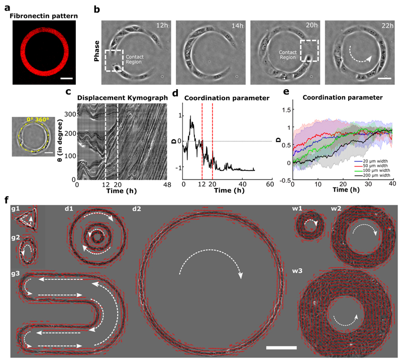
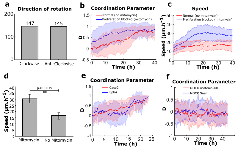
Using a micro-contact printing method on polydimethyl-siloxane (PDMS), we confined trains of Madin-Darby canine kidney epithelial cells (MDCK) on fibronectin-coated annular rings of controlled geometrical dimensions25. We mainly performed experiments using rings of 200 μm in outer diameter and 20 μm in width to limit cell migration along the ring to a one-dimensional track (Fig. 1a). This configuration minimizes lateral intercellular interactions and thus simplifies the analysis of the experimental system. After cell seeding, cells coalesced and spread to form random-sized short trains (Fig. 1b). We tracked the coordination of these trains by quantifying the coordination parameter D, defined as the average of the sum of cross products between cell velocity unit vector (v) measured from particle image velocimetry (PIV) and its respective position vector from the center of the ring (r) (n, total number of points in a given space) such that the normalized values of +1, -1, or 0 indicated clockwise, anticlockwise, or no preferential direction, respectively. At sub-confluency, cell trains displayed oscillatory migratory behaviors with no preferential direction (Movie 1) (Fig. 1c, d before 12h). However, we observed a surge in coordination parameter and average velocity as cell trains gradually met and fused into larger trains (Fig. 1b, c, d after 12 h). Eventually the coordination parameter came to a final, lasting plateau at ±1 when; cells reached confluency and began to rotate persistently in either a clockwise or anticlockwise direction with equal probability (Fig. 1d, at 20 h) (Extended Data Fig. 1a) (Movie 1). The coordination parameter gradually decreased in the end due to continued cell proliferation, a property reminiscent of cell jamming21,22,26,27(Extended Data Fig. 1b). When cells were treated with mitomycin to maintain a constant cell number, collective cell behaviors were unaffected over the first 40 hours, which was enough to reach confluency (Extended Data Fig. 1b). The average speed of rotation was higher for cells under mitomycin treatment (Extended Data Fig. 1c,d), probably due to the flow disturbance caused by continuing cell division under normal conditions28. To generalize our findings, we first varied the geometrical parameters characterizing cell confinement, including widths, perimeters and curvatures of closed patterns. Under these conditions, we did not affect the global rotational movements, demonstrating that this collective cell behavior was qualitatively independent of geometrical constraints (Fig. 1e,f) (Movie 2). In addition, we showed that our findings could be extended to other epithelial cell lines including Caco2 (Human epithelial colorectal adenocarcinoma cells) and Eph4 (Mouse mammary gland epithelial cells) that displayed similar behaviors (Extended Data Fig. 1e) (Movie 3).
Figure 1. Experimental setup and directed collective migration of MDCK trains.
a, Micro-contact printed pattern of Cy3 conjugated fibronectin in the shape of annular ring (ring outer diameter = 200 μm, track width = 20 μm). b, Phase contrast images of train of MDCK cells after initial seeding and spreading. Dashed white box indicates the contact regions where small cell trains merged into larger trains at 12h and 20h. c, Spatio-temporal displacement of cells traced along the circumferential midline of the ring track. Small train merging event is indicated by red dashed line. d, Evolution of coordination parameter, D, of cell trains in the ring with time (at t=20h cell train in ring begins to rotate in anti-clockwise direction). e, Coordination parameter, D, of cells in ring with different widths: 20 μm (n=62, m=3),50 μm (n=27, m=2),100 μm (n=8), 200 μm (n=8) respectively, shows a collective migration of cell trains independent of track width. f, Velocity vectors representing directed collective cell migrations for a variety of confined geometries (g1-triangle, g2-ellipse, g3-U shape), diameter (d1:outer-400 μm, middle-200 μm, inner-100 μm, d2-1mm), and width (w1-50 μm, w2-100 μm, w3-200 μm). All error bars indicated are standard deviations. Scale bars a, b, c: 50 μm and f: 200 μm.
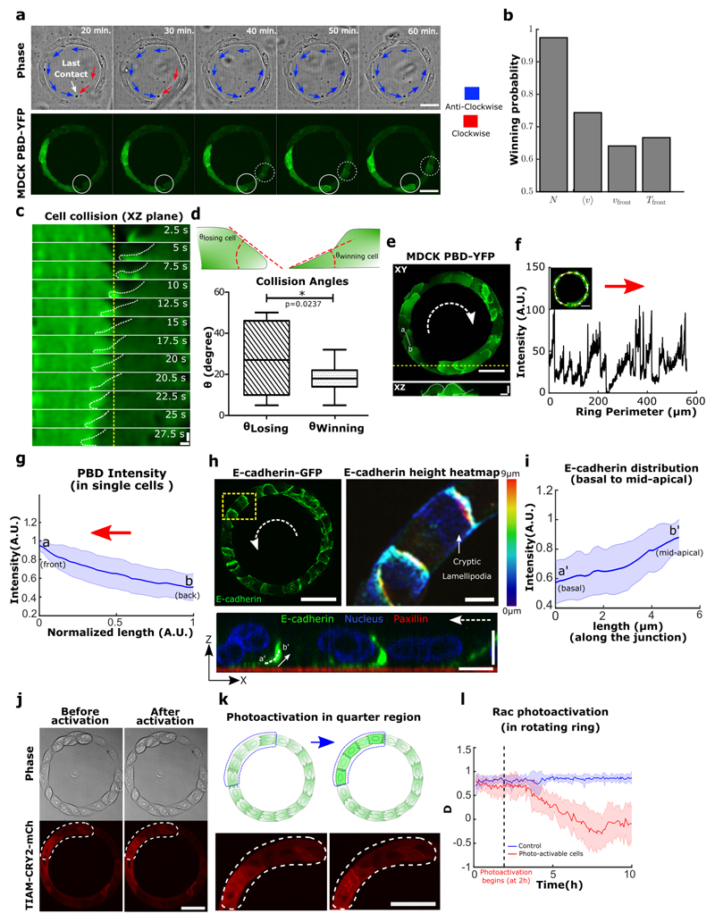
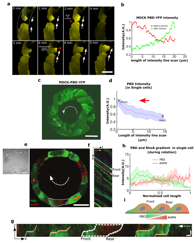
We first observed a spontaneous process of symmetry breaking that initiated global migration into one preferential direction (Fig. 2a, 20 min). The last contact between two leading cells that extend lamellipodial protrusions led to the change in direction of only one of the cells, a mechanism that may be partly reminiscent of contact inhibition of locomotion (CIL)29. Since CIL is based on opposite repolarization of both cells away from their contact site, we sought to study the dynamics of front-rear cell polarization in the ring using a fluorescent biosensor (P21 activated kinase Binding Protein, PBD) of active Rac1 and Cdc4230. We observed a reorientation of the PBD biosensor gradient in one of the two leading cells upon contact (Fig. 2a, 40 min) (Movie 4) with time scales of cell repolarization as fast as 3~4 min (Extended Data Fig. 2a,b).
Figure 2. Symmetry breaking in the epithelial train leads to the emergence of single cell polarity in migrating epithelia.
a, Confocal images (basal plane) of MDCK-PBD-YFP cells just before and after the establishment of last contact in the cell train. Phase contrast images show two oppositely migrating cell trains (red and blue arrows indicate the clockwise and anticlockwise direction respectively). Region indicating the establishment of last contact before confluency marked by solid circle (at 30 min.); Confocal sequential images showing the intensity of PBD-YFP biosensor signal during the last colliding event (dashed circle, at 40 min). b, Winning probability plot of cell trains upon collision, based on different parameters N (larger number of cells in a train), <v> (higher average speed of a train), Vfront (higher velocity of a train at colliding front), Tfront (higher traction forces of a train at the colliding front) (n=39, m=3 for N, <v>, Vfront and n=6 for Tfront). These parameters of colliding trains were measured 3 timepoints (i.e. 30 min.) before collision. c, Lamellipodial contact dynamics of the colliding cells as observed in XZ section of MDCK PBD-YFP cells (XZ Scale bar: 2 μm). d, Winning and losing cell angles (defined in schematic) as measured by the XZ section of the colliding cells (n=11, m=4). e, Confocal image of basal plane in MDCK-PBD cells showing the PBD biosensor distribution in cells. Dashed arrow indicates the rotation direction of the ring. XZ plane shows the establishment of Rac1 rich cryptic lamellipodia’s in cells (Scale bar: 4 μm). f, PBD intensity profile traced along the circumferential midline of ring track shown in e. g, Normalized PBD intensity profile in single cells (along line -ab in panel e, n=102 from 10 rings, m=3). The red arrow indicates the direction of cell migration. h, (Left) Confocal immunofluorescence image of E-cadherin (maximum intensity projection). Dashed white arrow indicates the direction of rotation in the ring. (Right) Expanded view (dashed yellow box in h, Scale bar: 10 μm) shows E-cadherin distribution height heatmap. ZX plane (bottom) corresponding to the dashed yellow region shows the formation of cryptic lamellipodia underneath the neighboring cells (Scale bar: 10 μm). Dashed white arrow indicates the direction of migration. i, Intensity profile of E-cadherin along the basal to mid-apical region (n=40 from 7 rings, m=1) (a'-b', marked in ZX plane of h, scale bar: 10 μm). j-k, Optogenetic-based homogeneous relocalization of TIAM (see methods) at cell membranes in a quarter of the ring (marked by dashed line). The schematic indicates the polarity perturbation post photoactivation. l, Evolution of the coordination parameter D as a function of time after photoactivation. Photoactivable cells in red (n=11, m=2) and WT control cells after similar photoactivation in blue (n=9, m=1). All error bars indicated are standard deviations. All scale bars unless mentioned specifically: 50 μm.
To further investigate the principles leading to this repolarization, we tested different parameters of both trains just before the last collision (3 time points before, i.e. 30 minutes). Our results indicated that the final direction of rotation at confluency was best predicted by the number of cells constituting the last colliding trains, then by their front speeds, with the winning train being the longest and the fastest (Fig.2b). Since prominent leader cells lead to high levels of orientation and polarization of followers31, we reasoned that winning cells should be then evidenced by larger lamellipodial protrusions. We thus analyzed the local protrusive activity of colliding cells before confluency. By measuring the contact angles of these two cells, we indeed found that the most spread cell with smaller angle of contact (i.e. large spread of lamellipodia) won over the other which repolarized in the opposite direction. Even more, the winning cell extended its lamellipodia beneath the other one eventually changing its polarity (Fig. 2c,d,e). Altogether, our findings demonstrated that coordinated rotational motion was driven by the repolarization of the smaller moving cell groups upon frontal collision due to local biased protrusive activity of leading cells.
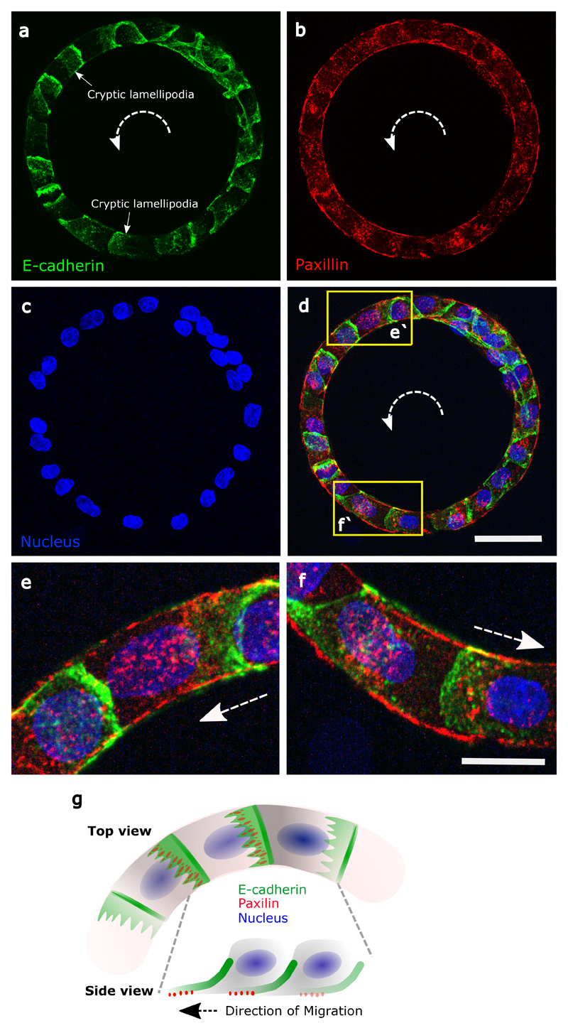
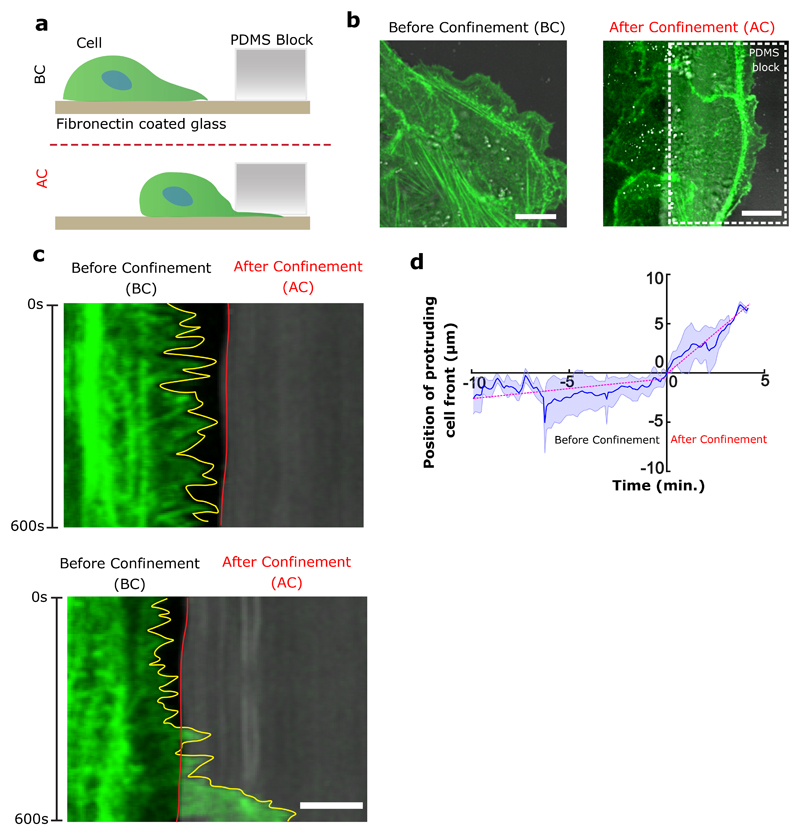
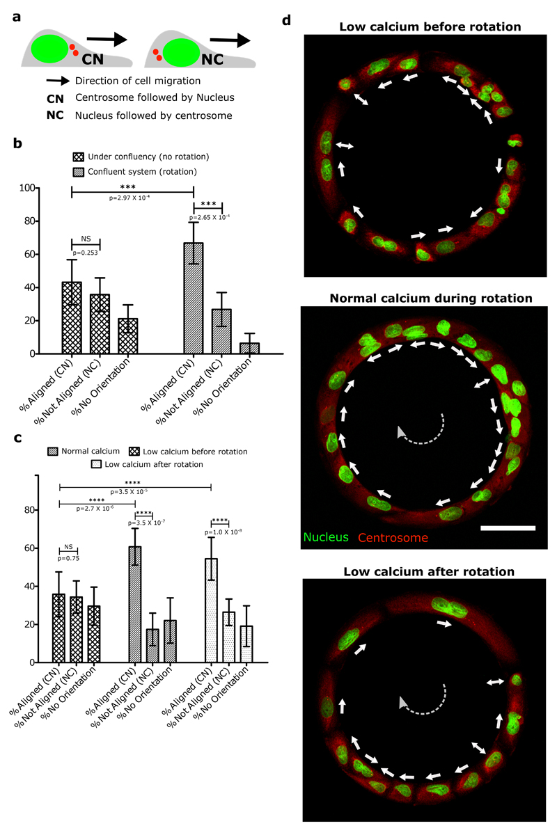
Shortly after reaching confluency, cells exhibited a persistent collective rotational movement. We then studied the maintenance of this persistent coordination over long-time scales. We first followed the distribution of the PBD sensor as an indicator of polarity gradient of Rac1 (Movie 5) (Fig. 2e,f,g). Surprisingly, we found that cells established a unidirectional polarity gradient at single cell level within collectively migrating monolayers. This observation was not restricted to 1-D confined monolayers but was also present in epithelial cells presenting lateral contacts as observed in wider rotating rings (Extended Data Fig. 2c,d). For the sake of simplicity, we thus focused our analysis on 1-D configurations. We then reasoned that the emergence of single cell polarization should display antagonistic activation of RhoA and Rac1 signals. Analyzing the active RhoA localization in cells using AHPH domain sensor32 further demonstrated the presence of an active contractility gradient at a single cell level opposite to the PBD gradient (Extended Data Fig. 2e,f,g,h,i). Such patterns of Rho GTPases activity were consistent with a picture of individual cell behavior controlling the movement of cell groups, rather than supracellular contractility as observed upon migration with free boundaries33. To further investigate the organization of these clusters, we performed immunostaining of cell-substrate and cell-cell adhesions based on paxillin and E-cadherin staining. It confirmed the presence of cryptic lamellipodia underneath the adjacent cell (Fig. 2h, Z-X plane; Extended Data Fig. 3a, b, c, d, e, f). Cadherin distribution also revealed a dissymmetrical organization with a gradient from basal to mid-apical level of the cells, including diffused clusters on the dorsal surface of the cryptic lamellipodium and a more concentrated E-cadherin region at the mid-apical region of the cells (Fig. 2i). We next sought to further understand the long-term persistency of these collective movements. The assembly of cryptic lamellipodia underneath the adjacent cell body led to the confinement of the protrusive structures. Cellular confinement by itself can promote actin retrograde flows and cell polarity34 that in turn reinforce cell persistency7. By introducing artificial confinement, we could demonstrate that confined lamellipodia promoted the assembly of large protrusive structures with higher stability and extension speeds, which could favor increased persistent cell migration as a collective (Extended Data Fig. 4a,b,c,d). During contact, such confinement of cryptic lamellipodia imposed by the rear of preceding cell through cadherin coupling can further prevent back the slippage of lamellipodia and contribute towards its persistence. This finding was even strengthened by the observation of a preferential alignment of the centrosome in front of the nucleus towards the direction of collective motion (around 60~70% of cells), which was not observed before rotation (Extended Data Fig. 5a,b).
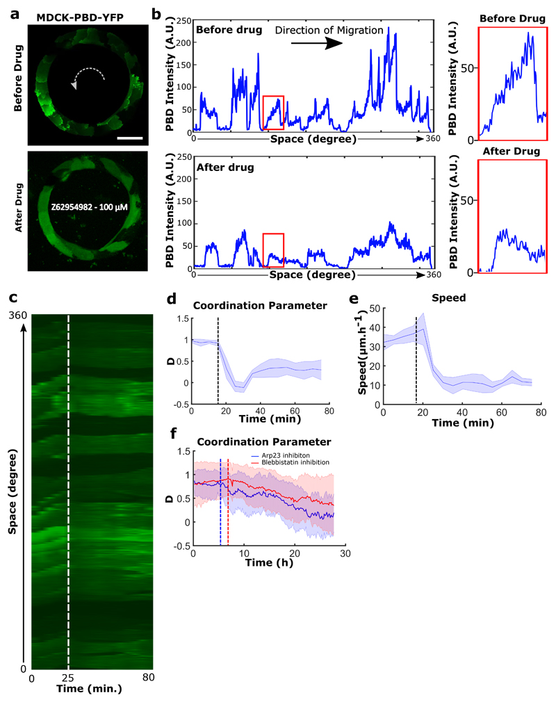
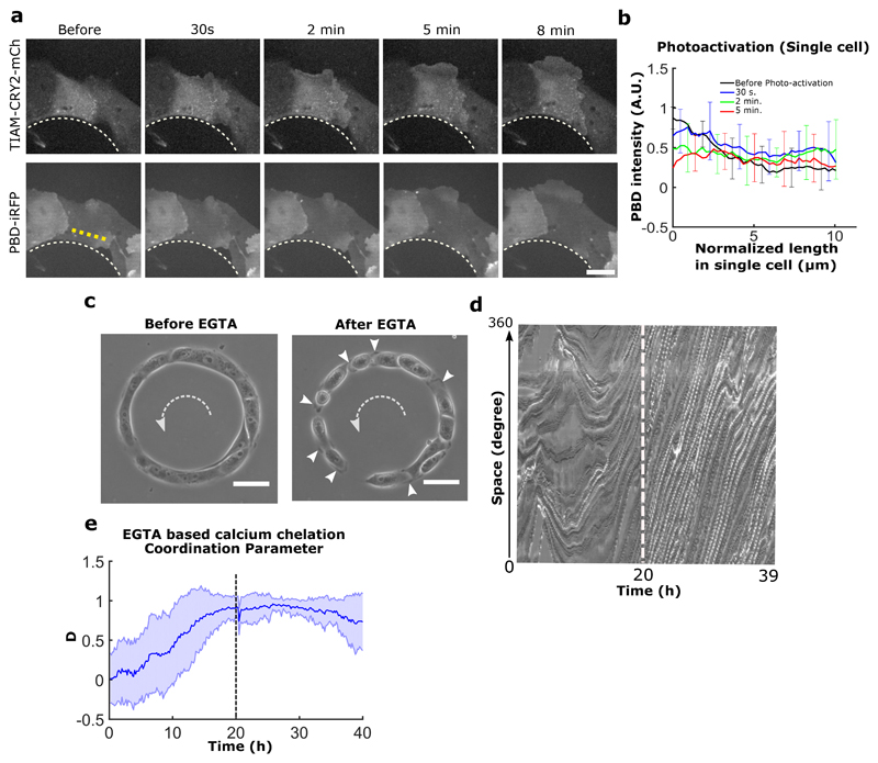
To test the principles behind the maintenance of persistent coordinated migration, we perturbed the system with the Rac-1 inhibitor Z62954982 (100 μM). It induced a rapid disappearance of PBD sensor distribution gradients in cells, and blocked rotation (Extended Data Fig. 6a,b,c,d,e). We then perturbed actin polymerization by preventing the branching of filaments through Arp2/3 inhibition by CK-666 (100 μM) (Extended Data Fig. 6f). Similarly, we observed a gradual decrease of cell velocities followed by a complete arrest of rotational motion. It suggests that both actin polymerization and lamellipodium formation are crucial to maintain such collective movements. We then examined the effect of local perturbations in front-back polarity of a few cells on the collective coordination of the entire system. To do so, we used optogenetics to flatten-out the Rac1 gradients in targeted groups of a few cells in each ring and thus perturb their polarity (Movie 6). This homogeneous whole cell Rac1 activation led to random extensions of lamellipodia among the targeted subgroups of cells, thereby stopping their directed migration. This progressively led to a total inhibition of the rotational migration over the entire ring (Fig. 2j,k,l and Extended Data Fig. 7a,b). These results pointed towards a process of cellular self-organization through polar extension of lamellipodia at the single cell level. However, other mechanisms could have contributed to such collective movements including propagating waves through acto-myosin contractility19,35. We thus analyzed the impact of Myosin II inhibition upon a high Blebbistatin concentration (80 μM). To our surprise, the coordination parameter dropped down gradually to reach half of its maximal value over several hours, showing myosin II contractility had less severe impact on collective behavior than Rac1 and Arp2/3 inhibitions (Extended Data 6f).
Our findings revealed that the initiation of coordinated movements occurred when cells reached confluency after the last collision of two migrating trains and unveiled the crucial role of lamellipodial protrusions and single cell polarity. We thus further investigated whether purely physical interactions by volume exclusion in a packed system could initiate coordinated rotational movement at confluent density or whether cell-cell adhesion was involved for initiating and maintaining a persistent collective rotation in the absence of a front edge. To do so, we perturbed cadherin-based adhesions by knocking down α-catenin36. Unlike control cells, α-catenin deficient cells did not initiate large-scale coordinated movements. Similar results were obtained with cells expressing the transcription factor Snail-1 in which E-cadherin mediated adhesion was also impaired21, demonstrating that cell-cell junctions were required to initiate collective movements (Extended Data Fig. 1f) (Movie 7).
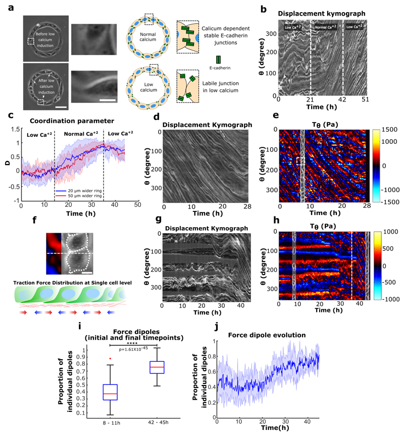
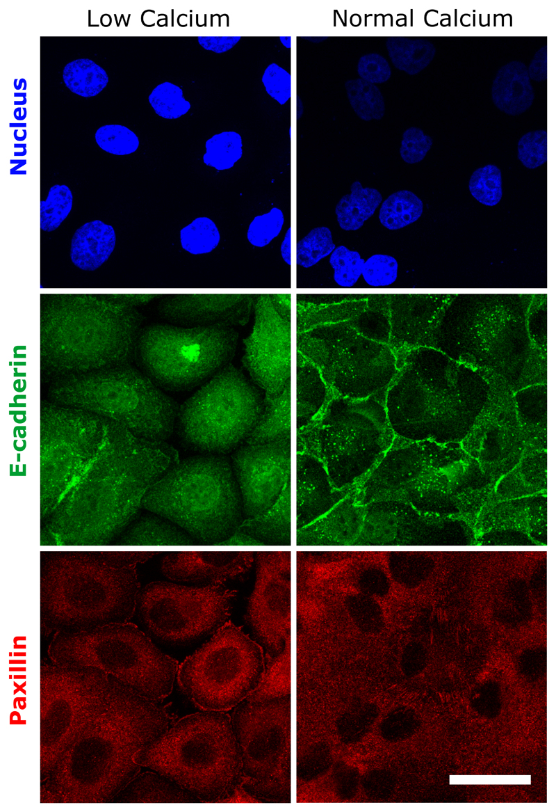
We then analyzed the coupling between cadherin-based adhesions and the maintenance of collective cell coordination. We disrupted cadherin-based junctions by switching calcium levels (Fig. 3a). As expected from our previous experiments using α-catenin knockdown and Snail1-overexpressing cells, we observed that cells at confluency failed to initiate a directed rotation in low calcium medium (Fig. 3b,c,0~21h). Once normal calcium levels were restored, we observed a surge in coordination parameter resulting in a strong directionality followed by the establishment of well-coordinated cell rotation after 5-6 hours (Fig. 3b,c,21~42h). More surprisingly, when cells were switched back to low calcium conditions, the ring continued rotation even after several hours (Movie 8) (Fig. 3b,c,42~51h). A similar result was obtained by chelating calcium through the addition of EGTA during the rotation (Extended Data Fig. 7c, d, e). Using immunofluorescence staining, we confirmed that low calcium treatment strongly perturbed the junctional recruitment of E-cadherin and led to a redistribution of focal contacts at the single cell periphery (Extended Data Fig. 8). Altogether, these findings show that the initiation of these collective movements depends on the establishment of proper cell-cell contacts but not their maintenance. This result could be explained by the tension induced during the assembly of cell-cell junctions. Since the formation of cell-cell contacts promotes the accumulation of Rho at the junctions37, it can produce sufficient forces to induce the extension of cryptic lamellipodia underneath the neighboring cell. By contrast, the absence of proper cell-cell junctions which induces stronger cell-substrate adhesions38,39 could restrict cellular extensions such as lamellipodia and thus impair the systematic front-rear organization of cryptic lamellipodia.
Figure 3. Establishment of directed collective cell migration depends on cell-cell junction strength but maintenance does not.
a, Phase contrast images of rings under normal and low calcium conditions. The white dashed box indicates the region detailed in the expanded view (Scale bar: 10 μm); low calcium media leads to the loosening of cell-cell junctions. Schematic depicting E-cadherin distribution in normal and low calcium conditions. b, Representative spatio-temporal displacement kymograph of cell trains in 20 μm ring. Under low calcium cells fail to coordinate and initiate rotation (before 21 h). The normal calcium media addition (at 21 h) initiates coordinated rotations in cell train. Introducing low calcium again (at 42 h) in system maintains the coordinated rotation. c, Coordination parameters D of 20 μm (n=25, m=2) and 50 μm (n=13, m=1) wider rings indicate the similar dynamics as observed in displacement kymograph b. d, Kymograph of rotating cell train on soft gels for traction force measurement, traced along the circumferential midline of the ring track. e, Spatio-temporal distribution of tangential traction forces of rotating cell train. Straightened cell train phase contrast image overlapped with the kymograph at a given time point to map the distribution of traction forces with respect to cells in train. f, Expanded view, white dashed square in e (Scale bar: 10 μm) and schematic representing the distribution of single cell level forces. g, Kymograph of sub-confluent short trains (before 36 h) and confluent rotating trains (after 36 h) on soft gels for traction force measurement. h, Spatio-temporal distribution of tangential traction forces of multiple short trains corresponding to initial stage (before 36h) and late-stage confluent rotating ring of cells (after 36h, marked by the white dashed line). i, Proportion of force dipoles during initial sub-confluent uncoordinated phase (8-11h) and confluent coordinated phase of cell trains in the ring (42-45h) (n=6). j, Time evolution of force dipoles from initial uncoordinated state to the final rotating state of cells in ring (n=6). All error bars indicated are standard deviations. All scale bars unless mentioned specifically: 50 μm.
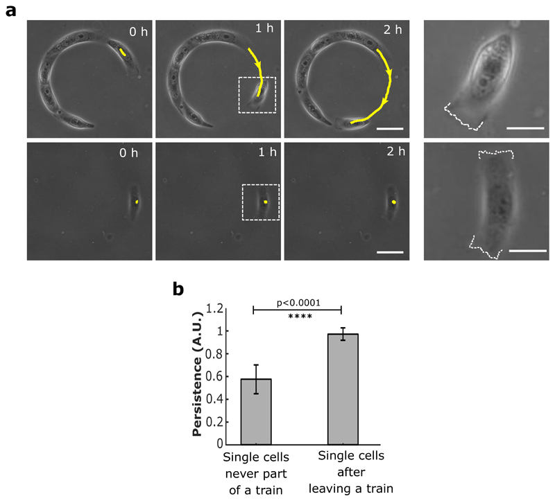
To further investigate the impact on single cell polarity, we analyzed the orientation of nucleus-centrosome axis with respect to the direction of rotation using calcium switch. We found a conserved polarity during collective cell rotation even after the junctions were disrupted (Extended Data Fig. 5a,c,d). Furthermore, we laser ablated 1-2 cells in a rotating cluster to mechanically disconnect adjacent cells. Even after the creation of a physical gap, we observed a persistent rotation of cells in their initial direction (Movie 9). Finally, we obtained further evidence supporting the ability of single cell to maintain a long-term polarity in the absence of E-cadherin junctions by observing single cell detachment from sub-confluent trains. These cells displayed a highly polarized persistent migration state at high speed (87 μm h-1), as opposed to isolated MDCK cells which did not migrate (Extended Data Fig. 9a, b). Altogether, theseresults demonstrated that the maintenance of collective cell migration was set by single cell behavior through the establishment of a sustained front-back polarity within cell clusters.
Our results highlight the existence of a new mode of coordination in addition to the classical view of collective cell migration being based on the establishment of long range coordination through intercellular contacts, as previously described for expanding cells in epithelial monolayers16,19,40. Therefore, we performed traction force measurements (TFM) on rotating rings and analyzed the forces applied to the substratum together with cell displacement (displacement kymographs). Interestingly, traction force kymographs exhibited distributions of force dipoles that scaled to one cell size and moved at the cellular speed (Fig. 3d,e,f). Neither the velocity nor the force fields showed a signature of long-range transmitted physical signals (Extended Data Fig. 10a, b, c). When PBD activity was co-registered along with TFM, we found a striking correlation between Rac1 gradient and the traction force dipoles (Extended Data Fig. 10d, e, f, g). We also observed that during the initial phase of uncoordinated sub-confluent cell trains, the traction forces were unevenly distributed with large forces becoming concentrated only at the free edges of the cellular clusters implicating a strong intercellular coupling, as previously described19 (Fig. 3g,h,i,j,8~11h). Forces evolved and were redistributed to establish a polarized force dipole at the single cell level after coordinated rotation was established (Fig. 3g,h,i,j,42~45h). To further investigate the mechanical role of cell-cell junction and potential force transmission in the tissue, we analyzed the force patterns in rotating rings upon calcium chelation. Under such conditions, cell-cell junctions were perturbed with focal adhesions redistributed at the edge of single cells (Extended Data Fig. 8). However, the overall coordination movement was conserved as previously mentioned together with force dipoles at the single cell level (Extended Data Fig. 10h). Alternatively, in α-catenin knock down cells the coordination of force dipole patterns never emerged due to lack of force coupling (Extended Data Fig. 10i). Interestingly, upon Arp2/3 inhibition, single cell level force dipoles were found to be diminished (Extended Data Fig. 10j). Overall, these findings elucidated two different phases of force distribution during collective migration: an initial phase based on large-scale forces transmission across cell clusters at sub-confluency as previously observed16,41, eventually leading to a phase exhibiting single cell-level force dipoles when the system reached a close state. Altogether, our results point toward a transition between open and closed systems where in the latter case, collective cell migration can take place through polarized entities at the single cell level.
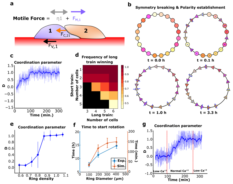
Our experimental findings led us to develop a particle-based model to validate our hypothesis regarding the respective roles of cell-cell contacts and cell polarity in driving collective rotation. We designed a minimalistic cell-based model of single cells moving on a 1D ring and driven by mechanical forces, without proliferation (see supplementary information). In the model, cells experience viscous cell-substrate friction and cell-cell contact forces. Their migration was driven by active forces and diffusion (Fig. 4a), their polarity could adopt three states which could change in a probabilistic, force-driven way: non-migratory, migrating clockwise, or migrating anti-clockwise. Our results showed that under these minimal mechanical assumptions, cell populations spontaneously coordinated their polarity and migration and rotated over long time scales (Movie 10a). We analyzed this symmetry breaking process in simulations (Fig. 4b). Cells were initially non-polarized (Fig. 4b, t=0.0h), and after some time formed several short trains of persistently polarized cells in either direction (Fig. 4b, t=1.0h). Opposite trains then collided, causing the repolarization of one of the colliding trains, and finally the collective rotation of the entire ring (Fig. 4b, t=3.3h). This coordination process was reminiscent of our experimental observations, a result confirmed by the gradual surge of the coordination parameter to a plateau (Fig. 4c). Importantly, we found that trains with more cells have a higher persistence (Fig. 4d), confirming that forces alone can drive a length-dependent repolarization process upon frontal collisions between cell trains, as seen in our experiments and in previously reported study42.
Figure 4. Mechanics-based simulations of epithelial cell migration on a ring.
a, Schematic of force balance in epithelial cell train. The forces are FV (viscous), FC (contact), FM (directed motile force) and the diffusion ŋ. b, Coordination emergence in a simulation. Circles: centers of non-polarized cells. Triangles: centers of polarized cells, pointing in their polarity direction (cell boundaries are not represented). Blue lines indicate the intensity of contact forces on a cell. c, Simulations reveal that persistent coordination emerges over time (blue pale line: coordination parameter for n=1 simulation, smoothed over time in the blue thick line). d, Colormap of the probability for the longer train to "win" a collision versus the number of cells in both trains. Black square: no data. n=20. e, Coordination parameter in simulations after 1000 timesteps (~400 minutes, averaged over last 8 minutes) versus cell density demonstrates that confluent density is necessary to achieve coordination. n=20 per point. f, Coordination time in experiments (n=20) and simulations (n=25) with varying ring sizes. g, Simulations varying the contact stiffness parameter over time to modulate cell-cell interactions (blue pale line: coordination parameter for n=1 simulation, smoothed over time in the blue thick line). All error bars indicated are standard deviations. * ring diameter is 200 μm unless stated otherwise.
Furthermore, as observed in experiments, coordination required cells to be under confluent density: when intercellular interactions were limited by a low global density, collective rotation failed to emerge (Fig. 4e). Again, consistent with the experimental data, persistent rotation emerged independently of the annular ring size, confirming that single-cell behaviors allow the long-range transmission of information over the entire system. Coordination times in both model and experiments (defined in supplementary information) increased with the ring diameter (Fig. 4f). To compare the dynamics of cell coordination in our model with experimental data, the spatial velocity correlation function on the ring was calculated (Extended Data Fig. 10k). We observed striking similarities between both patterns: periodic patterns larger than one cell progressively appear, suggesting the gathering of cells in several polarized trains, and disappear with time as cells migrate collectively. To study the importance of cell-cell junction-based interactions as experimentally determined through switching calcium levels, we decreased the ability of cells to repel each other upon contact (low numerical contact stiffness), facilitating as a result their movement past each other (Movie 10b, top) as compared to the case of cell collision based repolarization under normal calcium (normal numerical contact stiffness) (Movie 10b, bottom). The stiffness here is an effective parameter representing cell reaction to contact that encompasses mechanical interactions such as volume exclusion, as well as biochemical interactions (for more details refer to supplementary information). Remarkably, this alone was sufficient to recapture the effect of low Ca2+ levels: the initiation of coordination was made impossible, while collective movement was not impaired in already coordinated cell populations (Fig. 4g). Finally, simulations exhibited a transition in the migratory modes: cell-substrate friction is balanced by intercellular interactions during train formation and merging, and by motile forces when cells are fully coordinated (Extended Data Fig. 10l), which is reminiscent of the transition in force dipoles we observed experimentally. Taken together, these results indicate that our model successfully capture the overall dynamics of coordination emergence, highlighting the importance of single cell polarity and intercellular interactions in the resulting persistent rotation.
Collective cell migration has been described so far through the indispensable role of long-range interactions, the establishment of firm cell-cell junctions and supracellular coordination16,33,43. Here, we show that the maintenance of collective cell migration in monolayers lacking a free front edge relies on the emergence of single cell mechanical entities that coordinate their front-back polarity with the extension of lamellipodial-based structure underneath the front cell. Our findings reveal that this robust process relies on a long-term memory of the cellular polarized state which, once formed, becomes independent of cell-cell junctions. This driving mode of collective cell movements can recapitulate several situations observed in vivo during morphogenesis20,23,44,45, shed new light in the interpretation of previous studies by taking into account the local behavior of single cells and thus provide new mechanism to interpret directed cell migration during development, wound healing, and collective cancer cell invasion.
Material and Methods
Cell Culture, Microcontact printing and Cell Seeding
MDCK-WT, MDCK-Histone-GFP, MDCK-Ecadherin-GFP, MDCK-PBD-YFP, MDCK-α-Catenin KD, MDCK-Snail-1 over expressing cells, Caco2 and Eph4 cells were maintained in DMEM (Dulbecco's Modified Eagle Medium) (Invitrogen) supplemented with 10% FBS (Fetal Bovine Serum) (Invitrogen) 1% Penicillin-Streptomycin antibiotic (Invitrogen). All cells were maintained at 37°C and 5% CO2. Cells were passaged after reaching 70% confluency. The MDCK opto-Rac1 stable cell lines was obtained by lentiviral infection: lentiviral particles were produced by transfecting the pHR-TIAM-CRY2-mCherry or pLVX-CIBN-GFP-CAAX plasmids along with the vectors encoding packaging proteins (pMD2.G and psPax2) into HEK-293T cells. Viral supernatants were collected 2 days after transfection and MDCK cells were transduced at a MOI of 2. Clones with appropriate expression levels of TIAM-CRY2-mCherry and CIBN-GFP-CAAX were then selected.
Roughly 0.7 x 10⁶ cells were seeded on fibronectin (Sigma) patterns25 placed in a 35mm PDMS (Sylgard 184, Dow Corning) spin coated glass dish. Cells attached on fibronectin ring patterns within 45 min. to 1 hr. Cells were then washed once with DPBS (Dulbecco's phosphate-buffered saline) (Gibco) and once with DMEM media to prepare the sample for final imaging.
Microscopy
Long-term-time-lapse imaging to observe large scale epithelia dynamics was done using Nikon Biostation IMQ. We used 10X,20X objectives with NA 0.5 for imaging.
To observe the live spatio-temporal dynamics for the protein of interest, Nikon A1R confocal, Nikon CSU W1 spinning disk and Zeiss LSM 780 confocal were used. Most confocal images were taken with 60X/1.40 oil-immersion objective. Same set of confocal microscopes were used for acquiring immunofluorescence images.
Drug treatment
In most experiments the cell cycle was blocked using Mitomycin-c (Sigma Aldrich) added to the culture at 10 μg/ml for 1 hour, followed by washing twice with DPBS and twice with DMEM. The Arp 2/3 inhibitor, CK-666 (Sigma Aldrich) was used at 100 μM. The myosin II ATPase inhibitor Blebbistatin (Sigma Aldrich, B0560-1MG) was used at 80 μM. The Rac1 inhibitor Drug Z62954982 (Merck Millipore) was used at 100 μM. Primarily, to block cadherin adhesion, the entire normal media was replaced with low calcium media (~20 μM calcium) after 2 consecutive wash from low calcium media to remove any left-out calcium residue because of the prior existing normal media. Alternatively, EGTA (Sigma Aldrich) was added to the normal medium at a final concentration of 2 mM on our regular experiments with stiff substrate (spin-coated glass PDMS dishes) to partially chelate the calcium in the media. For the low calcium experiments done on soft substrates, we used EGTA concentration of 1.8 mM.
Preparation of low calcium media
Low calcium media was prepared by adding 1% FBS, 1% Penicillin-Streptomycin, 1% Sodium Pyruvate (Invitrogen) and 1% GlutaMAX (Gibco) to DMEM without calcium (Gibco). The final calcium concentration of the complete DMEM was approximately 20 μM.
Laser ablation of cells
We used a custom-built laser system integrated with a Nikon A1R MP laser scanning confocal microscope to ablate the cells in the cell monolayer through a Nikon apo 60X/1.40 oil-immersion objective. The laser used in the ablation system was in UV range with a pulse duration of 300 ps and a repetition rate of 1 kHz. The Power-Chip details: PNV-0150-100, Teem Photonics. We used a laser power of ~ 100 nW to 200 nW and the exposure time ranging from 0.5 seconds to 2 seconds to target cell nucleus in MDCK-histone-GFP cells to instantly ablate or blast the cell to make the epithelia discontinuous. Followed by the ablation, the images were acquired on the same microscope at 60X magnification. MDCK-histone-GFP cells were generously gifted from Sham Leilah Tlili (Mechanobiology Institute, Singapore)46.
Displacement and Velocity Kymographs
To obtain displacement kymographs, a centerline across the ring width is traced along its circular perimeter. Standard ImageJ RESLICE plugin is then used for the entire experimental movie to obtain a spatiotemporal displacement kymograph. To obtain the velocity field, we used an open source PIV (particle image velocimetry) MATLAB code named MatPIV47. To generate respective kymographs for obtaining a spatio-temporal distribution of velocities, the ring was spatially divided into 18 segments of 20° for each timepoint. The velocities were averaged in each segment to obtain a spatial profile. Similar steps were performed for every timepoint to obtain a heatmap representing a spatio-temporal distribution of the required dataset. Each segment of 20° is approximately equal to 31 μm in length.
Traction Force Microscopy (TFM) and traction force kymograph
The substrate for Traction Force Microscopy was prepared using soft silicone gel mixed in the ratio 1:1 (CyA:CyB) (Dow Corning). The method has been described in previous studies48,49. Briefly, a thin layer of the gel was spread on a glass bottom dish and then cured at 80°C for 2 hours. Cured gel was silanized using 5% solution of (3-aminopropyl) triethoxysilane (APTES, Sigma) in pure ethanol. This gel was later incubated for 5 minutes with 100 nm carboxylated fluorescent beads (Invitrogen) suspended in deionized (DI) water. Subsequently, the substrate was dried, and micro-contact printed with fibronectin using a thin water soluble polyvinyl alcohol (PVA) membrane which allows the transfer of fibronectin stamps on soft gel25,50. The PVA membrane was later dissolved and the non-contact printed areas were blocked using 2% Pluronics (Sigma) solution. The substrate was then washed and seeded with cells. Cells were allowed to grow until the micro-contact printed area reached confluency.
The samples were imaged using a Biostation IM-Q (Nikon) time lapse imaging microscope at 20X magnification for several hours. Images were acquired using the phase contrast and fluorescent channels to record images of the cell along with bead displacement.
For analysis, the imaging drifts were corrected in ImageJ (NIH) using the Image Stabilizer plugin51. To analyze the displacement field of beads, we used an open source PIV (particle image velocimetry) MATLAB code named MatPIV47. To reconstruct the traction force field from the obtained displacement field, an open source Fourier transform traction cytometry (FTTC) plugin was used in ImageJ52. To construct the final heat map of the tangential traction forces, the ring was divided into 72 equal sectors of 5° each and the values were averaged over the entire ring space for every 5° segment. The same was done for the entire time frame to produce spatio-temporal plots. Each segment of 5° was approximately equal to 7.85 μm.
Immunofluorescence and cell transfection
Cells were fixed with 4% formaldehyde in PBS at 37°C followed by blocking for 1 hour in a Saponin and BSA mixture at room temperature. In the case of centrosome immunofluorescence, methanol was used for fixation at -20°c. Cells were then rinsed with PBS 3 times. Subsequently, cells were incubated with primary antibodies for 1 hour followed by a PBS wash. Secondary antibodies were further incubated for 1 hr. After washing thoroughly with PBS 3 times, cells were mounted with coverslip and Vectashield mounting media (Vector laboratories) for imaging. Primary and secondary antibodies used for immunofluorescence are listed below:
Primary Antibodies:
Rabbit polyclonal anti-paxillin – ab3208, dilution 1:100, Abcam
Rat monoclonal anti-E-cadherin – U3254, dilution 1:100, Sigma
Mouse monoclonal anti-ϒ -Tubulin – T6557, dilution 1:200, Sigma
Rat monoclonal anti-Ecadherin (clone DECMA1) – MABT26, dilution 1:200, Sigma
Secondary Antibodies:
Alexa 488 conjugated donkey anti-rat IgG, dilution 1:100, Invitrogen
Alexa 568 conjugated goat anti-rabbit IgG, dilution 1:100, Invitrogen
Alexa 568 conjugated goat anti-mouse IgG, dilution 1:200, Life Technologies Ltd.
Nuclei staining – Hoechst reagent, dilution 1:1000, Invitrogen
Cell persistency calculation
Persistence is defined as the probability of the cell's velocity vector to remain in the same direction (either clockwise or anti-clockwise on the ring) between consecutive imaging frames (10 minutes per frame), calculated over the available time-lapse movie when a single detached cell is observed, according to the following formula:
Hence, persistence=1 when cells do not change direction, persistence=0.5 when cells change direction randomly, persistence=0 when cells engage in oscillatory motion with the sampling frequency.
Error bar and statistical testing
All error bars indicated in plots are the Standard deviations and the statistical testing are done using unpaired two tailed t test unless it is mentioned specifically for any other test. In figures, n represents total number of points considered (total number of rings, or cells respectively based on experimental requirement) and m represent the number of experiments. Wherever, m is not mentioned, it indicates one experiment set or a representative image.
Measurement of coordination time for different ring size
Cells were seeded under low calcium conditions on different sized ring micro-patterns to ensure that all rings reached nearly a full confluency after initial cell seeding. The low calcium media (~20 μM) ensured that cells were not able to initiate coordination dynamics in absence of calcium dependent adherens junction formation. Cells were imaged in low calcium media for few hours before introducing the normal calcium media (2 mM calcium). This protocol ensured that we present the same switching point to initiate coordination in all the different sized rings at confluent condition. We started out time recording from the point of introducing normal calcium media until the time at which each single cell in the ring began to rotate in the same direction (i.e. clockwise or anticlockwise). At this given point, we stopped our time recording in order to measure the total time taken. This time recorded was referred as the coordination time for different ring size diameter respectively. These experiments were performed with MDCK histone GFP stable cells to facilitate the ease of cell tracking.
Transfections
For simultaneous visualization of PBD and AHPH dynamics, YFP-PBD MDCK cells53 were transiently transfected with a plasmid driving the expression of mcherry AHPH (generous gift from Alpha Yap, The University of Queensland, Australia)32,54, Two million YFP-PBD MDCK cells were electroporated (Neon Transfection System Invitrogen) with 3-5 ug of plasmid encoding AHPH-mcherry in one pulse of 20 ms at 1650 V. After transfection cells were seeded directly on the ring patterns and live imaging was performed after 24 hours, with a Zeiss LSM 780 confocal microscope equipped with a 63 X oil immersion objective at a resolution of 0.8 μm z-stacks in a range of 6-7 μm, time-lapse was done for 8 hours at a rate of 1 frame every 10min. The pHR-TIAM-CRY2-mCherry, pLVX-CIBN-GFP-CAAX and PBD-iRFP plasmids used in optogenetics experiments were a kind gift of Mathieu Coppey55.
Vertical confinement of lamellipodia
To check the hypothesis of confinement mediated increase in lamellipodia activity. We designed a strategy based on our serendipitous observations during cell migration experiments earlier, where we confine cells by placing a PDMS block and latter releasing this physical confinement that allows cell to migrate. Our observations were that cells even though they are strictly confined and do not enter the PDMS block, but at times in few locations the lamellipodia would penetrate under the PDMS block but not the whole cell. We took advantage of this observation and devised a strategy to check our hypothesis. Here we placed a PDMS block on the glass bottom dishes coated with fibronectin for 1 hour with 50 μg/mL human plasma fibronectin (Merck Millipore) diluted in PBS and then washed three times with PBS. Then GFP-Actin cells were seeded on these dishes with confinement, were allowed to spread and live imaging was done to capture the events where lamellipodia has penetrated under the PDMS block (Extended Data Fig. 4). Live imaging was done with a Zeiss LSM 780 confocal microscope equipped with a 63 X oil immersion objective at a resolution of 0.15 μm z-stacks in a range of 2-2.5 μm, time-lapse was done for 5 min at a rate of 1 frame every 30 seconds. Analysis : For intensity profiles, a line was drawn on the ROI and the line scan was done using the plot profile plugin in ImageJ, the values obtained were then plotted. Graphs and statistical tests were done using GraphPad prism software.
Optogenetics experiments
Trains of opto-Rac1 cells were initially left to rotate on ring patterns. In order to perturb the front-rear Rac1-based polarity, we illuminated a region of interest corresponding to a quarter of the circumference of these rings with blue light (405 nm). Uniform activation of Rac1 in the cells in these regions resulted in a loss of cell polarity55 (Extended Data Fig. 7a,b). The loss of Rac1 gradients could be verified by the flattening of PBD-iRFP signal (Extended Data Fig. 7a,b).
The microscopy was performed using Zeiss Axio Observer Z1 mounted with spinning disk CSU-X1 (Yokogawa) unit. The photoactivation was performed using FRAP unit with 405 nm laser.
Analysis of ring closure
To determine what criterion predicted best the ring’s direction of rotation, we counted the number of rings in which the condition related to the given criterion was satisfied, such as for the criterion “train length” the condition was “the ring finally rotates in the same direction as the longer train”.
The criteria and conditions were the following:
N. 3 frames before (i.e 30 minutes before) ring closure, the train was divided in two, oppositely moving, parts. The cells in each part were manually counted using the phase contrast images and the condition tested was that the ring finally rotates in the same direction as the part with the larger number of cells.
<v>. The train was divided in two parts as before. The average (absolute value of the) speed <v> was computed in the two parts. The condition tested was that the ring finally rotates in the same direction as the part with larger <v>.
Vfront. The velocity was measured in a sector of 12.5° (44 μm) next to both train ends. The condition tested was that the ring finally rotates in the same direction as the faster end.
Tfront. The traction forces were measured as described, and their magnitude was averaged on a zone next to the end. Contrary to the velocity, this zone was manually defined on traction force kymographs to engulf the whole traction patch of the end. The condition tested was that the ring finally rotates in the same direction as the end with the larger traction magnitude.
Analysis of dipoles
The rings were first segmented using binarized transmission images to identify coherent trains. The number of dipoles at a given time was determined as the number of 0-crossings of the T(theta) curve along the ring at this time, excluding the areas that were not covered with cells. Then, the proportion of internal dipoles was obtained as follows: (i) the number of internal junctions Nij was defined as Nij = Nc-Nholes, where Nc is the number of cells in the ring and Nholes the number of holes between trains. (ii) The number of internal dipoles was defined as Nid = Nd – Nholes, where Nd is the total number of dipoles. Finally, the proportion of internal dipoles is Pid=Nid/Nij, so that it falls to 0 if all trains contract as units, and it goes to 1 if all cells contract individually even when they have cell-cell junctions.
Spatial correlation of traction forces and PBD signal
To quantify the spatial relationship between the traction force pattern and the cell polarity, we computed the normalized spatial cross-correlation coefficient defined as:
Where the angle brackets denote average, f is the orthoradial traction force, g is the PBD signal, and θ is the position along the ring. All the rings were first aligned so that they all rotate in the same direction. Then this function was computed for each time frame and averaged over time for each ring. Finally, the plot shows the average over the 6 rings and the error bars denote the standard deviation.
To check that the peak appearing close to Δθ = 0 does not stem accidentally from the signals’ properties, we shuffled one or both signals as follows. We picked a random phase-shift θshift(t) (all independent for various times, rings and for f and g), and transformed the signal as fshifted(θ, t) = f(θ + θshift(t), t). Then we proceeded as before, replacing f, g, or both f and g by their shifted version. That way we conserved the original signals’ structure but removed their potential correlations. Indeed, the resulting curves match the plot in Extended Data Fig. 10g for θ < 90° or θ > 0° showing that the peak for slightly negative θ denotes a significant correlation between the two signals.
Analysis of nucleus-centrosome axis orientation
After the confluency when rotation begins, the rings were allowed to rotate for ~24 hours. The sample was imaged for 2 hours with the help of Biostation IMQ (Nikon). Taking any one ring present at corner of sample as our reference point, we registered the direction of rotation for all the other rings. The samples were later fixed, and immunofluorescence was performed on them using the ϒ-Tubulin antibody (listed in the antibody table), here the nucleus was already labelled in GFP since we used MDCK-Histone-GFP cell line for this purpose. Further the alignment of centrosome and nucleus was recorded for every cell of the rings with respect to the rotation direction of the particular ring respectively. If the centrosome was placed before the nucleus in a way such that if the migration direction arrow tail is represented by the nucleus and the arrowhead is represented by the centrosomes, then this configuration is taken as CN mode or aligned mode (Centrosome placed before Nucleus). In other case, if the arrow of migration direction tail represents Centrosome and the arrowhead represents the Nucleus then this is NC configuration or not-aligned mode (Nucleus placed before centrosome).In all the other cases, where there are multiple centrosome present because of a dividing state of a cell or if the Nucleus-Centrosome are aligned in the perpendicular direction of the migration direction arrows, then this is taken as No-orientation condition.
For the cases where rings were not rotating in any definite direction, like in the case of under confluent rings and the low calcium condition (before symmetry breaking or before the rotation), we chose a fixed reference direction of rotation (clockwise in this case). We then calculated the Nucleus-Centrosome alignment in the similar way as the one explained above. Taking reference from the anti-clockwise direction did not show any positive correlation.
Extended Data
Extended Data Figure 1. Characterization of collective rotation in different conditions and different cell lines.
a, Distribution of rotation direction in rings (n=292, m=10). b, c, Coordination parameter and rotation speed evolution over time in the rings for cells under normal conditions (no-mitomycin, n=46,m=3) or proliferation blocked (with mitomycin, n=62,m=3) condition. The plateau corresponds to the emergence of a persistent rotation. d, Average speed of rotation for mitomycin treated (n=62, m=3) and untreated cells (n=46, m=3). e, Coordination parameters for different cell lines, Eph4 (n=10) and Caco2 (n=30). f, Coordination parameters D for MDCK-α-catenin-KD cells (n=30) and MDCK-Snail-1 over expressing cells (n=30). All error bars indicated are standard deviations.
Extended Data Figure 2. Repolarization time scale of single cell and single cell polarities.
a-b, Spatio-temporal montage of MDCK-PBD-YFP cells showing repolarization of a single cell upon collision. White arrows (dashed) show the direction of cell migration. Red arrow heads indicate the time of the collision (at 2 min.) and the appearance of Rac1 repolarization signal (at 6 min.), respectively. c, Confocal image of basal plane in a 50 μm wide ring shows a PBD gradients in all the cells indicating cell scale polarized Rac1 activities. d, Line intensity profile (as visualized by PBD biosensor intensity) shows average Rac1 gradient of single cells (n=42 from 2 rings, m=2) from multiple rings (as represented in a single cell marked by line -ab in panel c). e, MDCK cells expressing YFP-PBD and mcherry-AHPH. f, Saptio-temporal kymograph shows the single cells (marked with white dashed line) retain the front-rear characteristics during rotations. g, Distribution of AHPH (red) and PBD (green) at single cell level from the orthogonal view at one time point. Typical example of a single cell with boundaries marked in dashed white line (XZ scale bar: 2 μm). h, Line graph showing the intensity distribution of PBD and AHPH in single cells (n= 5 cells) of a rotating ring. i, Schematics showing the gradient of PBD and AHPH in single cells of a train. All error bars indicated are standard deviations. All scale bars unless mentioned specifically: 50 μm.
Extended Data Figure 3. Immunostainings of cell-substrate adhesions (paxillin) and cell-cell adhesion (E-cadherin).
a, Immunofluorescence for E-cadherin-GFP (Z-projection) in a rotating ring. Anti-clockwise direction is indicated by the white dashed arrows. The diffused E-cadherin distribution indicates the cryptic lamellipodia. b, Basal immunofluorescent paxillin staining labelled focal adhesions. c, Nuclei labelled in blue. d, Merge E-cadherin (green), paxillin (green) and nuclei (blue). (e-f) Images showing enlarged views of (e'-f'). g, Schematic showing single cells in rotating ring with cryptic lamellipodia revealed by polarized distributions of E-cadherin and paxillin. Scale bars: 50 μm (a-d), 20 μm (e-f)
Extended Data Figure 4. Cell confinement induces large protrusive activity and high speed of cellular protrusions at the cell front.
a, Schematics explaining the experimental set-up to confine front cell extensions. b, Representative images of actin-GFP cells on fibronectin coated glass substrates. Before confinement (BC) shows cells with a free leading edge and protruding activity. After confinement (AC) shows cells whose leading edges are confined underneath the confining PDMS block (scale bar: 10 μm). c, Kymograph of the cell front before (top) and after confinement (after) (scale bar: 5 μm). d, Cell edge position over time before and after confinement. Negative time correspond to the front edge position before confinement and positive time after confinement (n=10). The slope of curve (dashed magenta line) indicates the velocity of cell protrusions before (0.27 μm/min) and after confinement (1.58 μm/min), respectively. All error bars indicated are standard deviations.
Extended Data Figure 5. Measurement of cell polarity using orientation of nucleus-centrosome (NC) axis.
a, Schematic of nuclear-centrosome axis in a migrating polarized cell. The NC axis orientation is determined in cells double stained for nuclei (green) and centrosomes (red). This state of polarity is referred here as ‘CN’ when centrosome is placed ahead of nucleus in the direction of migration. When centrosome is placed behind the nucleus, then this state is referred as ‘NC’. Cells with multiple centrosomes and with centrosome either pointing radially inward or outward of the rings were categorized under “No Orientation”. b, NC axis orientation in uncoordinated sub-confluent rings (n=141, 13 rings) compared to confluent coordinated rotating rings (n=131, 11 rings). c-d, Representative immunofluorescence images of nucleus-centrosome positions in conditions of low calcium before the establishment of a coordinated rotation (n=216,12 rings), normal calcium conditions (n=191, 15 rings) and low calcium treatment after the initiation of coordinated rotation (n=385, 23 rings).
* Conditions where rings were not rotating persistently in any direction (sub-confluent and low calcium case before rotation), a fixed reference direction is chosen (clockwise in this case) in order to calculate the alignment of nucleus-centrosome axis. All error bars indicated are standard deviations. All scale bars: 50 μm
Extended Data Figure 6. Effects of Rac1, Arp2/3 and myosin-II inhibitions on rotating cell trains.
a, PBD signal distribution before (top) and after (bottom) addition of the Rac1 inhibitor Z62954982 (100 μM) on rotating rings. b, Intensity profile of PBD signal in entire rings before (top) and after (bottom) drug treatment. Expanded views (marked in red box) showing the disappearance of a single cell PBD signal gradient after drug addition. c, Kymograph of the PBD images traced along the circumferential midline of the ring track; the white dashed line indicates drug addition. d, e, Coordination parameters and speeds measured before and after Rac1 inhibition. Black dashed lines indicate drug addition (n=5, m=2). f, Coordination parameters evolution before and following Arp2/3 inhibition (CK666,100 μM, n=37) and myosin-II inhibition (Blebbistatin, 80 μM, n=30). Dashed vertical lines (blue and red color) indicate the point of drug addition respectively. All error bars indicated are standard deviations. All scale bars: 50 μm.
Extended Data Figure 7. Rac1 polarity gradient perturbation using optogenetics and compromising cell-cell adhesion strength by EGTA treatment.
a-b, Time evolution of PBD signal in cells after homogeneous photoactivation of TIAM. Post activation, TIAM begins to localize at cell membrane. Within 5 minutes of the photoactivation, the PBD gradient flattens in cell indicating the loss of Rac1 polarity in the cell (n=11, from 7 cells). Intensity is measured along the dashed yellow line as indicated in representative panel a. Scale bar: 20 μm. c, Phase contrast imaging shows the loosening of cell-cell junctions after EGTA treatment. Exposed cryptic lamellipodia of migrating cells are marked by white arrowheads after cell-cell junction loosening. The dashed white arrows indicate the direction of rotation. d, Representative displacement kymograph of phase contrast imaged cells traced along the circumferential midline of the ring track before and after EGTA treatment (2 mM) (white dashed line indicates the time of EGTA addition ~ 20 h). e, Coordination parameter of rotating cell rings, before and after EGTA treatment (black dashed line indicates the time of EGTA addition, 20 h) (n=40, m=1). All error bars indicated are standard deviations. All scale bars unless mentioned specifically: 50 μm.
Extended Data Figure 8. Cell-cell junctions and focal adhesions in the presence of low and normal calcium media.
Nucleus (blue)-E-cadherin (green)-paxillin (red) immunofluorescence of cell monolayers. E-cadherin accumulation at cell-cell contacts detected in normal medium, disappear in low calcium. By contrast, paxillin staining reveals the presence of focal adhesions in both conditions. Scale bar: 20 μm.
Extended Data Figure 9. Single cell migration persistency in the absence of cell-cell junctions.
a, Top panel: Phase contrast images of cell trains at low density that show spontaneous detachment of single cells at the free edges. Sequential images showing cell detachment followed by a polarized persistent migration. Expanded view of the dashed white box (last column) reveals the active lamellipodial activity on one side of the cell (marked with white dashed line). Bottom panel: Control experiment showing the behavior of a single MDCK cell with no previous contact with other cells. No preferential migration is observed. Both edges of the cell show lamellipodial activity as marked by dashed white line in the expanded view (last column) from white dashed square box. (Scale bars: 20 μm). The yellow lines indicate the distance travelled by the cells at given times. b, Persistence of cell movements for single isolated cells (n=12) and for single cells detaching from sub-confluent trains (n= 11). All error bars indicated are standard deviations. All scale bars unless mentioned specifically: 50 μm.
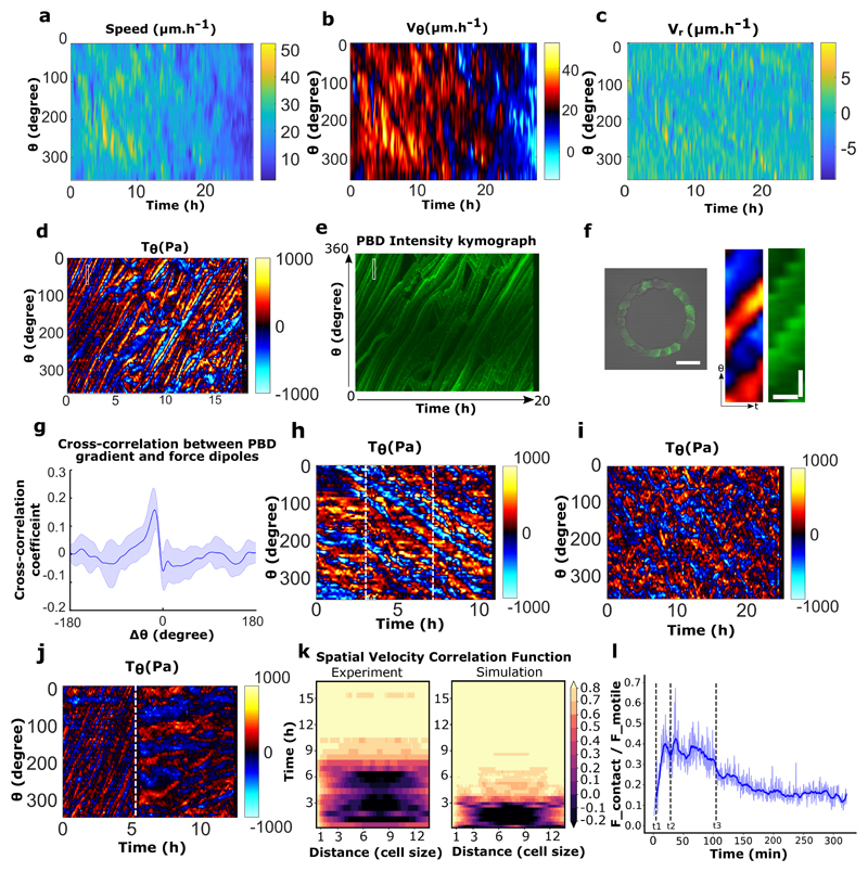
Extended Data Figure 10. Spatio-temporal distribution of velocities and forces under various condition.
a, Spatio-temporal kymograph of cell train speed for the experiment referred in Fig.3d. b-c, Spatio-temporal tangential speed and radial speed kymograph for the experiment referred in Fig.3d. d, Tangential traction force spatio-temporal profile of MDCK-PBD cells in rotating ring. e, Corresponding PBD intensity profile and tangential traction force distribution as shown in panel d. f, MDCK-PBD cells on ring pattern (Left). Expanded view of corresponding regions of interest for PBD gradients and traction force dipoles (marked by white rectangular box in panel d, e) (right). Scale bar, Ө: 10 μm, t: 30 minutes. g, Cross correlation of tangential traction force profile and PBD signal show a high spatial correlation (n=10,m=2). h, Tangential traction forces post EGTA treatment indicate single cell level force dipoles in a rotating ring before and after EGTA treatment (beginning of rotation is marked by the white dashed line ~ at 3h), EGTA addition is marked by the white dashed line at ~7h. i, Tangential traction force distribution in α-catenin KD cells. j, Tangential traction force pattern before and after Apr2/3 inhibition. The white dashed line marks CK666 drug addition (100 μM). k, Spatial velocity correlation C(x’,t) as a function of distance x’ in experiments and simulations (both with 15 cells) showed similar migration dynamics. where x, x’ are curvilinear abscissas, u is the 2 angular velocity (positive in counter-clockwise direction) and t is time. l, Ratio of contact and motile forces in 1 simulation (taken from Fig. 4b), recapitulating the force-distribution transition observed in Fig. 2f-h: before polarization starts (t<t1), and once collective rotation is established (t>t3), cells migrate as single dipole and their viscous interaction with the substrate is mainly balanced by their motility. During the coordination process (between t1 and t3), cells form larger dipoles and the contact forces contribute to viscous force balance (t1: cells start polarizing, until they are all polarized at t2, and rotate collectively from t3) (blue thick line: smoothing over time). All error bars indicated are standard deviations. All scale bars unless mentioned specifically: 50 μm.
Supplementary Material
MDCK cells break symmetry and rotate collectively on 1-D ring confinement. Ring outer diameter 200 μm, track width of 20 μm.
MDCK cell rotations under geometrical confinements with different shape (g1-triangle,g2-ellipse, g3-U shape), length(diameter d1:outer-400 μm, middle-200 μm, inner-100 μm, d2-1mm ) and width (w1-50 μm, w2-100 μm, w3-200 μm).
Other cell types display collective behavior: a, Eph4 and b, Caco2
Time scale of Rac1 based repolarization in single cells upon collision with the larger train
Rac1 based front-rear polarity is established in each cell of the rotating ring after symmetry breaking.
Optogenetics: photoactivation of TIAM at 120 minutes in a quarter region of rotating ring (marked by blue dashed line) is indicated by its junctional localization, which follows a gradual arrest of coordinated rotations in ring.
MDCK cells fail to initiate rotation and break symmetry a, MDCK-α-Catenin-KD cells and, b, MDCK-Snail-1 over expressing cells
MDCK cells fail to initiate rotation in presence of low calcium condition but breaks symmetry and begins to rotate upon addition of normal calcium. However, once symmetry is broken, MDCK cells continue to rotate even when low calcium condition is reintroduced.
Epithelia continuity is not required for the maintenance of rotations: Laser ablation of cells in the rotating ring maintains the directed migration of cells.
a, Numerical simulations reproduce the symmetry breaking process and polarity establishment in cell rings. Geometrical shapes represent cell centers. Circles: non-polarized cells. Triangles: polarized cells, pointing in their polarity direction. Cell boundaries are not represented, though blue lines indicate the intensity of contact forces on a cell. b, Cell swapping upon migrating train collisions in the case of low cell-cell junction strength-based interactions (top) when compared to cell repolarization during collision in normal cell-cell junction strength (bottom).
Acknowledgements
The authors thank Delphine Delacour, Jacques Prost, Masahiro Sokabe, Yusuke Toyama, Raphael Voituriez, and group members from MBI and IJM for helpful discussions and critical reading of the manuscript. We would like to thank MBI science communication team member Steven Wolf and Andrew Wong for the proof reading of manuscript. We also thank the MBI Microfabrication Core (Gianluca Grenci and Mohammed Asraf) and MBI Microscopy Core (Felix Margadant) for continuous support and would like to extend our thanks to Ong Hui Ting for her valuable suggestions in image processing and image analysis. We also acknowledge the ImagoSeine core facility of the Institut Jacques Monod, and members of IBiSA and France-BioImaging (ANR-10-INBS-04) infrastructures. The authors are grateful to W. J. Nelson and F. Martin-Belmonte for their generous gift of MDCK cell lines.
Funding
Financial support from the Mechanobiology Institute (CTL, BL), the European Research Council under the European Union's Seventh Framework Programme (FP7/2007-2013) / ERC grant agreements n° 617233 (BL), USPC-NUS collaborative program (RMM, BL), Agence Nationale de la Recherche (ANR) “POLCAM” (ANR-17- CE13-0013), the LABEX “Who am I?” (ANR-11-LABX-0071), the Ligue Contre le Cancer (Equipe labellisée) (BL, RMM), BBSRC through the grants BB/K018175/1, BB/P003184/1 (AJK), and the MERLION PhD program (French Embassy in Singapore) are gratefully acknowledged.
Footnotes
Author contributions: S.J. and B.L. conceived the study and designed the experiments. B.L., R.M.M, A.J.K., and C.T.L supervised the project. S.J., G.H.N.S.N., V.Cel., S.D.B., M.H. and T.C. performed experiments; S.J.,T.C., J.A., G.H.N.S.N., S.D.B., M.H., R.M.M., P.M. and B.L. did experimental data analysis; V.C. and A.J.K. designed and implemented the numerical model, ran the simulations and analyzed the resulting data. RMM and P.M. contributed new reagents, modeling and computational tools. B.L., S.J. and V.C. wrote the manuscript. All authors critically proofread the manuscript.
Competing interests: Authors declare no competing interests.
Data and code availability: Source data are available for this paper. The codes for modeling and simulation are available at https://github.com/Viccach/Jain_et_al_2020.git. The home-made codes for data visualization and plotting are available upon request. All other data that support the plots within this paper and other finding of this study are available from the corresponding author upon reasonable request.
References
- 1.Friedl P, Gilmour D. Collective cell migration in morphogenesis, regeneration and cancer. Nature Reviews Molecular Cell Biology. 2009;10:445–457. doi: 10.1038/nrm2720. [DOI] [PubMed] [Google Scholar]
- 2.Friedl P, Hegerfeldt Y, Tusch M. Collective cell migration in morphogenesis and cancer. International Journal of Developmental Biology. 2004;48:441–449. doi: 10.1387/ijdb.041821pf. [DOI] [PubMed] [Google Scholar]
- 3.Ridley AJ, et al. Cell Migration: Integrating Signals from Front to Back. Science. 2003;302:1704–1709. doi: 10.1126/science.1092053. [DOI] [PubMed] [Google Scholar]
- 4.Raftopoulou M, Hall A. Cell migration: Rho GTPases lead the way. Developmental Biology. 2004;265:23–32. doi: 10.1016/j.ydbio.2003.06.003. [DOI] [PubMed] [Google Scholar]
- 5.Svitkina T. The Actin Cytoskeleton and Actin-Based Motility. Cold Spring Harbor Perspectives in Biology. 2018;10 doi: 10.1101/cshperspect.a018267. a018267. [DOI] [PMC free article] [PubMed] [Google Scholar]
- 6.Mogilner A, Oster G. Cell motility driven by actin polymerization. Biophysical journal. 1996;71:3030–3045. doi: 10.1016/S0006-3495(96)79496-1. [DOI] [PMC free article] [PubMed] [Google Scholar]
- 7.Maiuri P, et al. Actin Flows Mediate a Universal Coupling between Cell Speed and Cell Persistence. Cell. 2015;161:374–386. doi: 10.1016/j.cell.2015.01.056. [DOI] [PubMed] [Google Scholar]
- 8.Mayor R, Etienne-Manneville S. The front and rear of collective cell migration. Nature Reviews Molecular Cell Biology. 2016;17:97–109. doi: 10.1038/nrm.2015.14. [DOI] [PubMed] [Google Scholar]
- 9.Zaritsky A, et al. Propagating Waves of Directionality and Coordination Orchestrate Collective Cell Migration. PLOS Computational Biology. 2014;10:e1003747. doi: 10.1371/journal.pcbi.1003747. [DOI] [PMC free article] [PubMed] [Google Scholar]
- 10.Khalil AA, Friedl P. Determinants of leader cells in collective cell migration. Integrative Biology. 2010;2:568. doi: 10.1039/c0ib00052c. [DOI] [PubMed] [Google Scholar]
- 11.Yang Y, et al. Probing Leader Cells in Endothelial Collective Migration by Plasma Lithography Geometric Confinement. Sci Rep. 2016;6:1–11. doi: 10.1038/srep22707. [DOI] [PMC free article] [PubMed] [Google Scholar]
- 12.Vedula SRK, et al. Emerging modes of collective cell migration induced by geometrical constraints. Proceedings of the National Academy of Sciences. 2012;109:12974–12979. doi: 10.1073/pnas.1119313109. [DOI] [PMC free article] [PubMed] [Google Scholar]
- 13.Ladoux B, Mège R-M. Mechanobiology of collective cell behaviours. Nature Reviews Molecular Cell Biology. 2017 doi: 10.1038/nrm.2017.98. [DOI] [PubMed] [Google Scholar]
- 14.Farooqui R, Fenteany G. Multiple rows of cells behind an epithelial wound edge extend cryptic lamellipodia to collectively drive cell-sheet movement. Journal of Cell Science. 2005;118:51–63. doi: 10.1242/jcs.01577. [DOI] [PubMed] [Google Scholar]
- 15.Gov NS. Traction forces during collective cell motion. HFSP Journal. 2009;3:223–227. doi: 10.2976/1.3185785. [DOI] [PMC free article] [PubMed] [Google Scholar]
- 16.Sunyer R, et al. Collective cell durotaxis emerges from long-range intercellular force transmission. Science. 2016;353:1157–1161. doi: 10.1126/science.aaf7119. [DOI] [PubMed] [Google Scholar]
- 17.Das T, et al. A molecular mechanotransduction pathway regulates collective migration of epithelial cells. Nature Cell Biology. 2015;17:276–287. doi: 10.1038/ncb3115. [DOI] [PubMed] [Google Scholar]
- 18.Hayer A, et al. Engulfed cadherin fingers are polarized junctional structures between collectively migrating endothelial cells. Nature Cell Biology. 2016;18:1311–1323. doi: 10.1038/ncb3438. [DOI] [PMC free article] [PubMed] [Google Scholar]
- 19.Serra-Picamal X, et al. Mechanical waves during tissue expansion. Nature Physics. 2012;8:628–634. [Google Scholar]
- 20.Sato K, et al. Left–right asymmetric cell intercalation drives directional collective cell movement in epithelial morphogenesis. Nature Communications. 2015;6 doi: 10.1038/ncomms10074. 10074. [DOI] [PMC free article] [PubMed] [Google Scholar]
- 21.Doxzen K, et al. Guidance of collective cell migration by substrate geometry. Integrative Biology. 2013;5:1026. doi: 10.1039/c3ib40054a. [DOI] [PubMed] [Google Scholar]
- 22.Palamidessi A, et al. Unjamming overcomes kinetic and proliferation arrest in terminally differentiated cells and promotes collective motility of carcinoma. Nat Mater. 2019 doi: 10.1038/s41563-019-0425-1. [DOI] [PubMed] [Google Scholar]
- 23.Cetera M, et al. Epithelial rotation promotes the global alignment of contractile actin bundles during Drosophila egg chamber elongation. Nature Communications. 2014;5 doi: 10.1038/ncomms6511. 5511. [DOI] [PMC free article] [PubMed] [Google Scholar]
- 24.Krndija D, et al. Active cell migration is critical for steady-state epithelial turnover in the gut. Science. 2019;365:705–710. doi: 10.1126/science.aau3429. [DOI] [PubMed] [Google Scholar]
- 25.Vedula SRK, et al. Methods in Cell Biology. Vol. 120. Elsevier; 2014. Microfabricated Environments to Study Collective Cell Behaviors; pp. 235–252. [DOI] [PubMed] [Google Scholar]
- 26.Bi D, Yang X, Marchetti MC, Manning ML. Motility-Driven Glass and Jamming Transitions in Biological Tissues. Physical Review X. 2016;6 doi: 10.1103/PhysRevX.6.021011. [DOI] [PMC free article] [PubMed] [Google Scholar]
- 27.Sadati M, Taheri Qazvini N, Krishnan R, Park CY, Fredberg JJ. Collective migration and cell jamming. Differentiation. 2013;86:121–125. doi: 10.1016/j.diff.2013.02.005. [DOI] [PMC free article] [PubMed] [Google Scholar]
- 28.Rossen NS, Tarp JM, Mathiesen J, Jensen MH, Oddershede LB. Long-range ordered vorticity patterns in living tissue induced by cell division. Nature Communications. 2014;5 doi: 10.1038/ncomms6720. [DOI] [PMC free article] [PubMed] [Google Scholar]
- 29.Stramer B, Mayor R. Mechanisms and in vivo functions of contact inhibition of locomotion. Nature Reviews Molecular Cell Biology. 2016 doi: 10.1038/nrm.2016.118. [DOI] [PubMed] [Google Scholar]
- 30.Machacek M, et al. Coordination of Rho GTPase activities during cell protrusion. Nature. 2009;461:99–103. doi: 10.1038/nature08242. [DOI] [PMC free article] [PubMed] [Google Scholar]
- 31.Reffay M, et al. Orientation and Polarity in Collectively Migrating Cell Structures: Statics and Dynamics. Biophysical Journal. 2011;100:2566–2575. doi: 10.1016/j.bpj.2011.04.047. [DOI] [PMC free article] [PubMed] [Google Scholar]
- 32.Tse YC, et al. RhoA activation during polarization and cytokinesis of the early Caenorhabditis elegans embryo is differentially dependent on NOP-1 and CYK-4. MBoC. 2012;23:4020–4031. doi: 10.1091/mbc.E12-04-0268. [DOI] [PMC free article] [PubMed] [Google Scholar]
- 33.Shellard A, Szabó A, Trepat X, Mayor R. Supracellular contraction at the rear of neural crest cell groups drives collective chemotaxis. Science. 2018;362:339–343. doi: 10.1126/science.aau3301. [DOI] [PMC free article] [PubMed] [Google Scholar]
- 34.Liu Y-J, et al. Confinement and Low Adhesion Induce Fast Amoeboid Migration of Slow Mesenchymal Cells. Cell. 2015;160:659–672. doi: 10.1016/j.cell.2015.01.007. [DOI] [PubMed] [Google Scholar]
- 35.Aoki K, et al. Propagating Wave of ERK Activation Orients Collective Cell Migration. Developmental Cell. 2017;43:305–317.e5. doi: 10.1016/j.devcel.2017.10.016. [DOI] [PubMed] [Google Scholar]
- 36.Benjamin JM, et al. αE-catenin regulates actin dynamics independently of cadherin-mediated cell–cell adhesion. The Journal of Cell Biology. 2010;189:339–352. doi: 10.1083/jcb.200910041. [DOI] [PMC free article] [PubMed] [Google Scholar]
- 37.Acharya BR, et al. A Mechanosensitive RhoA Pathway that Protects Epithelia against Acute Tensile Stress. Developmental Cell. 2018;47:439–452.e6. doi: 10.1016/j.devcel.2018.09.016. [DOI] [PubMed] [Google Scholar]
- 38.Ravasio A, et al. Regulation of epithelial cell organization by tuning cell–substrate adhesion. Integrative Biology. 2015;7:1228–1241. doi: 10.1039/c5ib00196j. [DOI] [PMC free article] [PubMed] [Google Scholar]
- 39.de Rooij J, Kerstens A, Danuser G, Schwartz MA, Waterman-Storer CM. Integrin-dependent actomyosin contraction regulates epithelial cell scattering. The Journal of Cell Biology. 2005;171:153–164. doi: 10.1083/jcb.200506152. [DOI] [PMC free article] [PubMed] [Google Scholar]
- 40.Petitjean L, et al. Velocity fields in a collectively migrating epithelium. Biophys J. 2010;98:1790–1800. doi: 10.1016/j.bpj.2010.01.030. [DOI] [PMC free article] [PubMed] [Google Scholar]
- 41.Trepat X, et al. Physical forces during collective cell migration. Nature Physics. 2009;5:426–430. [Google Scholar]
- 42.Desai RA, Gopal SB, Chen S, Chen CS. Contact inhibition of locomotion probabilities drive solitary versus collective cell migration. Journal of The Royal Society Interface. 2013;10 doi: 10.1098/rsif.2013.0717. 20130717–20130717. [DOI] [PMC free article] [PubMed] [Google Scholar]
- 43.Tambe DT, et al. Collective cell guidance by cooperative intercellular forces. Nature Materials. 2011;10:469–475. doi: 10.1038/nmat3025. [DOI] [PMC free article] [PubMed] [Google Scholar]
- 44.Cetera M, Leybova L, Joyce B, Devenport D. Counter-rotational cell flows drive morphological and cell fate asymmetries in mammalian hair follicles. Nature Cell Biology. 2018;20:541–552. doi: 10.1038/s41556-018-0082-7. [DOI] [PMC free article] [PubMed] [Google Scholar]
- 45.Wang H, Lacoche S, Huang L, Xue B, Muthuswamy SK. Rotational motion during three-dimensional morphogenesis of mammary epithelial acini relates to laminin matrix assembly. Proceedings of the National Academy of Sciences. 2013;110:163–168. doi: 10.1073/pnas.1201141110. [DOI] [PMC free article] [PubMed] [Google Scholar]
- 46.Tlili S, et al. Collective cell migration without proliferation: density determines cell velocity and wave velocity. Royal Society Open Science. 2018;5 doi: 10.1098/rsos.172421. 172421. [DOI] [PMC free article] [PubMed] [Google Scholar]
- 47.Sveen J. An introduction to MatPIV v. 1.6. 27. 2004 [Google Scholar]
- 48.Vedula SRK, et al. Epithelial bridges maintain tissue integrity during collective cell migration. Nature Materials. 2014;13:87–96. doi: 10.1038/nmat3814. [DOI] [PubMed] [Google Scholar]
- 49.Vedula SRK, et al. Mechanics of epithelial closure over non-adherent environments. Nature Communications. 2015;6 doi: 10.1038/ncomms7111. [DOI] [PMC free article] [PubMed] [Google Scholar]
- 50.Yu H, Xiong S, Tay CY, Leong WS, Tan LP. A novel and simple microcontact printing technique for tacky, soft substrates and/or complex surfaces in soft tissue engineering. Acta Biomaterialia. 2012;8:1267–1272. doi: 10.1016/j.actbio.2011.09.006. [DOI] [PubMed] [Google Scholar]
- 51.Kang L. The image stabilizer plugin for ImageJ. 2008 [Google Scholar]
- 52.Martiel J-L, et al. Methods in Cell Biology. Vol. 125. Elsevier; 2015. Measurement of cell traction forces with ImageJ; pp. 269–287. [DOI] [PubMed] [Google Scholar]
- 53.Kraynov VS, et al. Localized Rac Activation Dynamics Visualized in Living Cells. 2000;290:5. doi: 10.1126/science.290.5490.333. [DOI] [PubMed] [Google Scholar]
- 54.Priya R, et al. Feedback regulation through myosin II confers robustness on RhoA signalling at E-cadherin junctions. Nature Cell Biology. 2015;17:1282. doi: 10.1038/ncb3239. [DOI] [PubMed] [Google Scholar]
- 55.de Beco S. Optogenetic dissection of Rac1 and Cdc42 gradient shaping. Nat Commun. 2018;9:1–13. doi: 10.1038/s41467-018-07286-8. [DOI] [PMC free article] [PubMed] [Google Scholar]
Associated Data
This section collects any data citations, data availability statements, or supplementary materials included in this article.
Supplementary Materials
MDCK cells break symmetry and rotate collectively on 1-D ring confinement. Ring outer diameter 200 μm, track width of 20 μm.
MDCK cell rotations under geometrical confinements with different shape (g1-triangle,g2-ellipse, g3-U shape), length(diameter d1:outer-400 μm, middle-200 μm, inner-100 μm, d2-1mm ) and width (w1-50 μm, w2-100 μm, w3-200 μm).
Other cell types display collective behavior: a, Eph4 and b, Caco2
Time scale of Rac1 based repolarization in single cells upon collision with the larger train
Rac1 based front-rear polarity is established in each cell of the rotating ring after symmetry breaking.
Optogenetics: photoactivation of TIAM at 120 minutes in a quarter region of rotating ring (marked by blue dashed line) is indicated by its junctional localization, which follows a gradual arrest of coordinated rotations in ring.
MDCK cells fail to initiate rotation and break symmetry a, MDCK-α-Catenin-KD cells and, b, MDCK-Snail-1 over expressing cells
MDCK cells fail to initiate rotation in presence of low calcium condition but breaks symmetry and begins to rotate upon addition of normal calcium. However, once symmetry is broken, MDCK cells continue to rotate even when low calcium condition is reintroduced.
Epithelia continuity is not required for the maintenance of rotations: Laser ablation of cells in the rotating ring maintains the directed migration of cells.
a, Numerical simulations reproduce the symmetry breaking process and polarity establishment in cell rings. Geometrical shapes represent cell centers. Circles: non-polarized cells. Triangles: polarized cells, pointing in their polarity direction. Cell boundaries are not represented, though blue lines indicate the intensity of contact forces on a cell. b, Cell swapping upon migrating train collisions in the case of low cell-cell junction strength-based interactions (top) when compared to cell repolarization during collision in normal cell-cell junction strength (bottom).


