

Abstract

Quantum spin Hall
(QSH) insulators host edge states, where the
helical locking of spin and momentum suppresses backscattering of
charge carriers, promising applications from low-power electronics
to quantum computing. A major challenge for applications is the identification
of large gap QSH materials, which would enable room temperature dissipationless
transport in their edge states. Here we show that the layered mineral
jacutingaite (Pt2HgSe3) is a candidate QSH material,
realizing the long sought-after Kane–Mele insulator. Using
scanning tunneling microscopy, we measure a band gap in excess of
100 meV and identify the hallmark edge states. By calculating the  invariant, we confirm the topological nature
of the gap. Jacutingaite is stable in air, and we demonstrate exfoliation
down to at least two layers and show that it can be integrated into
heterostructures with other two-dimensional materials. This adds a
topological insulator to the 2D quantum material library.
invariant, we confirm the topological nature
of the gap. Jacutingaite is stable in air, and we demonstrate exfoliation
down to at least two layers and show that it can be integrated into
heterostructures with other two-dimensional materials. This adds a
topological insulator to the 2D quantum material library.
Keywords: Topological insulator, Low-dimensional materials, Quantum spin Hall effect (QSH), Scanning tunneling microscopy (STM)
The QSH state1,2 has
first been realized experimentally, at cryogenic temperatures, in
HgTe quantum wells.3 Interestingly, the
prototype QSH insulator is actually graphene, when it was realized
by Kane and Mele that its Dirac quasiparticles are gapped and characterized
by a  topological invariant if spin orbit coupling
(SOC) is considered.4,5 However, the low SOC in graphene
results in a gap of only a few μeV, making its topological properties
a mere theoretical curiosity. To realize a Kane–Mele insulator,
a material is needed with the honeycomb lattice of graphene, but having
large SOC.4 In the past few years there
has been a tremendous effort to find a layered material conforming
to these requirements. From the point of view of applications, the
candidate material forming this “heavy metal graphene”,
should ideally have the following characteristics. It should have
a topological gap above room temperature, to enable room temperature
dissipationless charge transport. The van der Waals bonding between
the layers of the material should be weak enough6 to enable exfoliation by the well-known methods developed
for 2D materials. This would enable integration into heterostructures
with the vast numbers of other 2D quantum materials discovered to
date.7,8 Such a combination with other 2D materials
can enable a high degree of control over the edge states.7 For example, in proximity with 2D superconductors,
Majorana quasiparticles could be formed.9 Lastly, it should be stable in air under ambient conditions, making
the material widely usable.
topological invariant if spin orbit coupling
(SOC) is considered.4,5 However, the low SOC in graphene
results in a gap of only a few μeV, making its topological properties
a mere theoretical curiosity. To realize a Kane–Mele insulator,
a material is needed with the honeycomb lattice of graphene, but having
large SOC.4 In the past few years there
has been a tremendous effort to find a layered material conforming
to these requirements. From the point of view of applications, the
candidate material forming this “heavy metal graphene”,
should ideally have the following characteristics. It should have
a topological gap above room temperature, to enable room temperature
dissipationless charge transport. The van der Waals bonding between
the layers of the material should be weak enough6 to enable exfoliation by the well-known methods developed
for 2D materials. This would enable integration into heterostructures
with the vast numbers of other 2D quantum materials discovered to
date.7,8 Such a combination with other 2D materials
can enable a high degree of control over the edge states.7 For example, in proximity with 2D superconductors,
Majorana quasiparticles could be formed.9 Lastly, it should be stable in air under ambient conditions, making
the material widely usable.
One possibility to realize a QSH system, is to increase the SOC in graphene by placing it in proximity to materials with a large atomic number,10−12 either with adatoms13,14 or in a substrate.15−17 The resulting SOC induced gap is on the order of 10 meV at best. An alternative is to find a material with an intrinsically large topological gap,18 such as a bismuth honeycomb layer on SiC,19,20 with a band gap of 0.8 eV. However, the crystal structure and therefore the topological properties of this bismuthene are linked to the SiC support, limiting its applicability. Similar constraints arise in the case of stanene21 and other group IV honeycomb layers and perhaps for bismuth (111) bilayers.22,23
Among materials that exist as freestanding single layers, the 1T′ phase of transition metal dichalcogenides are predicted to be QSH insulators.24 For MoS2, WSe2, and WTe2 the hallmark edge states have been identified by scanning tunneling microscopy (STM)25−29 and by charge transport measurements for WTe2.30 However, MoS2 and WSe2 are metastable and easily convert to the 2H phase,31 while WTe2 is stable in the 1T′ polymorph but rapidly oxidizes in air. None of the above examples are stable under ambient conditions, with the possible exception of Bi14Rh3I9.32 However, due to the complex crystal structure and ionic bonding between the layers,33 it is not clear if it is possible to isolate a single layer of it.
Here we present
evidence via STM measurements that jacutingaite
(Pt2HgSe3), a naturally occurring mineral,34,35 realizes a room temperature Kane–Mele insulator, satisfying
all of the above criteria. By measuring on the basal plane of exfoliated
multilayer crystals, we identify a bulk band gap and edge states within
this gap, localized to monolayer step edges, showing a decay length
of 5 Å into the bulk. We reproduce the measured band gap and
edge states by density functional theory calculations (DFT) of the
monolayer. By calculating the  invariant, we show that the band gap is
expected to be topologically nontrivial, in accordance with the previous
prediction of Marrazzo et al.36 Within
our experiments Pt2HgSe3 has proven to be stable
under ambient conditions, on a time scale of months to a year, as
either bulk or exfoliated crystals with a thickness down to 1.3 nm,
equivalent to one or two layers. This is no surprise since jacutingaite
is a mineral;34,35 therefore, it should be stable
not just under ambient but at pressures and temperatures relevant
to geological processes.
invariant, we show that the band gap is
expected to be topologically nontrivial, in accordance with the previous
prediction of Marrazzo et al.36 Within
our experiments Pt2HgSe3 has proven to be stable
under ambient conditions, on a time scale of months to a year, as
either bulk or exfoliated crystals with a thickness down to 1.3 nm,
equivalent to one or two layers. This is no surprise since jacutingaite
is a mineral;34,35 therefore, it should be stable
not just under ambient but at pressures and temperatures relevant
to geological processes.
The sample we investigated was grown synthetically, as described previously.35 For preparation and characterization details, see supplementary section S1. Additionally, we have measured and calculated the Raman spectrum of bulk crystals; see supplementary section S6. In the following, we focus on STM measurements of exfoliated thick crystals on a gold surface. The measurements were carried out in UHV at a base pressure of 5 × 10–11 Torr and a temperature of 9 K.
Jacutingaite is a ternary compound having a “sandwich-like” structure reminiscent of transition metal dichalcogenides, with a platinum layer between selenium and mercury. It can be regarded as “heavy metal graphene”, since states around the SOC induced gap are localized on the honeycomb lattice formed by Pt and Hg atoms (see bottom inset in Figure 1a).36 Indeed, in the absence of SOC these bands give rise to a Dirac cone at the K points of the Brillouin zone (see Figure 1b).
Figure 1.

Atomic and electronic structure of Pt2HgSe3. (a) Atomic resolution, topographic STM image of Pt2HgSe3, stabilization parameters: 10 pA, −0.8 V. Sublattices are marked with a red triangle and rectangle, respectively. Right inset: atomic structure of Pt2HgSe3, top and side view. Bottom inset: Contour plot of the density of states within the conduction band in a 200 meV interval. (b) Band structure of Pt2HgSe3 single layer, from DFT calculation, without (gray) and with (colored) SOC. Size and color of the dots is proportional to the weight of Pt, Hg, or Se in the respective electronic state. (c) Comparison of measured dI/dV(V) signal (blue) and calculated (red) density of states. The measurement was conducted on the defect free basal plane of Pt2HgSe3. The calculation is for a monolayer of Pt2HgSe3. Band gap highlighted in gray. (d) Measured dI/dV spectra as a function of distance from a step edge on the basal plane. The spectra are offset for clarity. Topographic STM image of the step shown on the left side of the spectra. The positions of the spectra are shown by dots with the respective colors.
The atomic resolution STM images of the basal plane reflect this honeycomb structure; for an example, see Figure 1a. The topographic image shows a sublattice symmetry broken graphene-like arrangement of the local density of states (LDOS), with the unit cell shown by a red rhombus. The unit cell size is measured to be 7.3 Å, in agreement with the expected unit cell size (7.34 Å) measured via X-ray diffraction.35 Upon closer examination, we can observe a difference in the apparent height of the two sublattices, marked by red squares and triangles in Figure 1a. This sublattice symmetry breaking is a consequence of the buckled honeycomb nature of the Pt–Hg lattice. The buckling means that each inequivalent sublattice resides on opposing sides of the single layer, similarly to silicene or germanene.
Measuring the differential
tunneling conductivity (dI/dV(V)) on the defect free basal
plane reveals a bulk band gap of 110 mV, shown by the gray shading
in Figure 1c. Importantly,
if measured far away from any surface defects or edges, the dI/dV signal goes to zero inside the gap,
showing that this energy range is indeed devoid of electronic states.
The measured LDOS is in excellent agreement with density functional
theory (DFT) calculations of the monolayer; see red plot in Figure 1c. The 110 meV gap
shown here is a best case scenario, where we purposely selected an
area devoid of any surface defects. The large defect concentration
of the basal plane (see supplementary section S3) makes the local electronic structure inhomogeneous. In
order to characterize the gap rigorously, we have measured the band
gap from 982 individual spectra in an area 10 × 10 nm2. The mean gap value was found to be 78 meV, with a standard deviation
of 27 meV (for details see supplementary section S4). The topological nature of the band gap is established
by calculating the  index (see supplementary section S7). By comparing the red and blue plots in Figure 1c, we can immediately
see that the calculated LDOS of the monolayer accurately reproduces
the dI/dV spectrum measured on the
top layer of a bulk crystal. Also considering that the measurement
is not reproduced by the calculated surface DOS of a four layer slab,
suggests that the top Pt2HgSe3 layer in our
measurement is decoupled from the bulk (see supplementary section S7.1). This is supported by our STM measurements of
the monolayer step height, which is found to be 0.7 Å larger
than the intrinsic interlayer distance of 5.3 Å (see inset in Figure 2a and Figure 1Sc of the Supporting Information).
index (see supplementary section S7). By comparing the red and blue plots in Figure 1c, we can immediately
see that the calculated LDOS of the monolayer accurately reproduces
the dI/dV spectrum measured on the
top layer of a bulk crystal. Also considering that the measurement
is not reproduced by the calculated surface DOS of a four layer slab,
suggests that the top Pt2HgSe3 layer in our
measurement is decoupled from the bulk (see supplementary section S7.1). This is supported by our STM measurements of
the monolayer step height, which is found to be 0.7 Å larger
than the intrinsic interlayer distance of 5.3 Å (see inset in Figure 2a and Figure 1Sc of the Supporting Information).
Figure 2.

Characterizing the edge state. (a) Topographic STM image of a zigzag edge. Stabilization parameters: −0.85 V bias, 30 pA. dI/dV spectra shown in (e) are measured along the green line. Black dotted lines mark the edge, as in (a–c, e–g). Inset: height section of the step. (b) dI/dV image, measured in the same area as the topographic image in (a), outside the gap in the conduction band, at bias voltage −0.85 V. (c) dI/dV image, measured in the same area as (a, b), at a bias voltage of −1.15 V inside the gap. The position of the edge state is marked between two dotted black lines. (d) Top: dI/dV signal modulation along the edge state. Section between the black dotted lines in (c). Bottom: fast Fourier transform of the line section. (e) Plot of dI/dV spectra measured as a function of distance from the edge. The spectra are recorded along the green line in (c). (f) Calculated LDOS of the conduction band. (g) Calculated LDOS of the edge state, using a broadening of 2.6 Å. LDOS periodicity along the edge is equal to the unit cell size (shown by arrowed black line). Edge state LDOS is concentrated between the dotted black lines. (h) Averaged section across the edge state within the purple dotted box shown in (c). The decay of the edge state into the bulk is of the order of 5 Å, the same as the decay in the calculation: (g) For extended data, see section 10 of the Supporting Information.
Although the measured LDOS is reproduced by the DOS of the monolayer, the sample is heavily n doped. In the case of the measured curve in Figure 1c, the Fermi level marked by zero bias is shifted above the conduction band, leaving the band gap at −1.15 eV. A possible source of the high n doping might be defects or inhomogeneities in the bulk crystal (see supplementary section S3). A strong indicator of these is the presence of PtSe2 in the sample and that, in the case of all crystals, we observe a large number of adsorbates even on the freshly cleaved basal plane. Investigating the doping in exfoliated crystals down to the bilayer thickness, we find that the n doping is considerably less, with the Fermi level being at least 0.5 V closer to the topological gap than for the bulk (see supplementary Figures 13S and 14S). This points to inhomogeneities and defects as being the most likely cause of the doping, as well as the enlarged interlayer spacing.
Having established the location of the band gap in the dI/dV spectra, let us focus on investigating the presence of the predicted QSH edge states.36 Other QSH material candidates, such as WTe2,29 Bi14Rh3I9,33 and ZrTe537 also reproduce the LDOS of the monolayer, when measuring the top of bulk crystals with STM. For these materials, monolayer steps on the bulk surface show the hallmark edge states residing in the band gap. In Figure 1d, we show individual dI/dV spectra measured near a monolayer step edge on a thick flake, having hundreds of layers. The positions of the spectra are marked by similarly colored dots on the STM image of the step. At a position 2 nm away from the step edge, the spectra reproduce the LDOS measured deep in the bulk of the sample. Moving even closer to the edge, at a distance of ∼1 nm, the LDOS inside the band gap starts to increase, indicating the presence of an in gap state. An extra state localized to the edge also appears above the conduction band, at −0.2 V, which is a fingerprint of the edge structure. During our STM investigation, straight and atomically clean edges were always of the zigzag kind. Therefore, we checked the atomic and electronic structure of this edge orientation terminated by Se, Pt, and Hg, by optimizing the atomic lattice of monolayer ribbons in DFT. The only atomic configuration that shows the hallmark edge state above the conduction band and is energetically stable, is a Se terminated zigzag edge (see Figure 3 and supplementary section S8). Thus, we have used this trivial edge state above the conduction band to identify the type of zigzag edge present in the measurement. This allows us to accurately reproduce the LDOS of the edge in our calculations.
Figure 3.
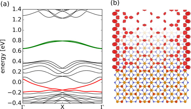
Pt2HgSe3 nanoribbon. Topological edge states. (a) Band structure of a 3.2 nm wide zigzag ribbon, calculated using DFT. The topological edge state is shown in red, while the trivial edge state above the conduction band is shown in green. (b) LDOS contour plot of the topological edge state integrated over the whole topological band.
In the following we examine in more detail the increased LDOS near the monolayer step edge. In Figure 2c we show an image of the dI/dV signal at a voltage inside the gap, measured along an edge shown in Figure 2a. An increased dI/dV signal indicates an increased LDOS near the step. In all panels on Figure 2 the black dotted lines mark the position of the edge. The decay of the edge state into the bulk is found to be on the order of 5 Å, in agreement with prediction.36 Taking a section between the dotted black lines (Figure 2d), one observes that the edge LDOS is modulated by the atomic periodicity, as expected for a topological edge state.20,38 A further hallmark of topological edge states is that the state is not perturbed by the presence of a defect, visible in the top-right area of Figure 2a. If backscattering would take place due to the defect this would result in a modulation of the local density of states along the edge. The wavelength of this modulation is determined by the change is crystal momentum of the scattered electron, which can be obtained from the dispersion relation along the edge, shown in Figure 3a. The voltage used in the measurement (−1.15 V) corresponds to an energy in the middle of the gap. At this energy, the change in crystal momentum would result in a periodicity of 13.1 Å related to intraband scattering.20 To check the presence of backscattering, we show the Fourier transform of the dI/dV signal along the edge in Figure 2d. We observe the peak corresponding to 1/0.73 nm–1 unit cell periodicity, but the peak for backscattering is clearly absent. This conclusion is further strengthened by additional Fourier analysis on a longer, irregular edge (see supplementary section S5). This analysis is essentially a 1D analogue of probing the suppression of backscattering on the 2D surface state of strong topological insulators by STM measurement of quasiparticle interference patterns.39
Finally, comparing the dI/dV images with the calculated LDOS map inside the topological gap (Figure 2g) and of the complete valence band (Figure 2f), we find that there is good agreement with the measurements. The calculated LDOS maps reproduce both the atomic periodicity along the edge state, as well as its decay length of 5 Å. With such a small decay length, it is expected that the edge state would start to develop at defect sites inside the basal plane, such as in the bottom-right corner of Figure 2c. A better example of this effect can be observed in the supplementary Figure 4Sd.
The relatively
weak van der Waals bond between the monolayers of
Pt2HgSe3 makes it possible to exfoliate the
material, potentially to the monolayer limit.6 We demonstrated this possibility by using the standard “scotch
tape method” to exfoliate thin flakes onto a SiO2 substrate or a polymer stack, as used in dry stacking of 2D materials40 (see Figure 4a–c). Using dry stacking, it should be possible
to place Pt2HgSe3 on the surface of a high Tc superconductor, enabling the investigation
of high temperature Majorana zero modes.9 The thinnest crystals we were able to prepare by conventional scotch
tape exfoliation onto SiO2 substrates was 5 layers. However,
these crystals have lateral sizes below 1 μm (see Figure 4c), severely limiting their
usefulness. Exfoliating onto fresh gold surfaces41 increases the lateral size of the flakes significantly
and their thickness, measured by AFM is 1.3 nm (see Figure 4d,e). However, these thin flakes
are found to be highly disordered. For more details, see supplementary section S9. These results show
that it should be possible to exfoliate single layers of Pt2HgSe3 onto SiO2 and especially gold substrates,
but the material homogeneity and defect density of the bulk crystals
needs to be improved significantly. Further improvements in crystal
quality could also be a key to probing the dual topological nature42,43 of Pt2HgSe3 such as in the case of Bi2TeI.44 This is because Pt2HgSe3 is predicted to not only be the long sought after
Kane–Mele insulator, but in bulk form it is also a topological
crystalline insulator and a  insulator.42,43,45
Figure 4.

Exfoliation of Pt2HgSe3. (a) Stack of jacutingaite on graphite, prepared by dry stacking. (b) AFM image of the flake before the transfer supported on a PMMA substrate. (c) AFM image of a thin flake, having a thickness of 2.6 nm, corresponding to approximately five single layers. Inset: height section of the flake along the green line. (d) Exfoliation of jacutingaite onto a gold (111) surface. The thinnest flakes are marked by the red dotted line. (e) AFM image of the thinnest flakes, inside the area marked with red in (d). Inset: height section along the blue line.
One of the most promising QSH materials is monolayer 1T′-WTe2, but the chemical stability of Pt2HgSe3 in air and it is band gap above room temperature, clearly sets it
aside. The main difference being that WTe2 rapidly oxidizes
under ambient conditions and shows the QSH effect only below a temperature
of 100 K.30 Our results establish that
jacutingaite is a new and widely accessible platform to explore the
properties of helical one-dimensional electron systems20,46 and should be available for charge transport measurements, even
in the monolayer, if the defect concentration and sample homogeneity
can be improved. Recent theoretical studies highlight the possibility
of superconductivity in doped Pt2HgSe3,47 this could open a way to explore the coexistence
of topological edge states in proximity to a superconductor in the
same material system. Additionally, a nonzero  index48 makes
Pt2HgSe3 a fertile playground to explore higher
order topology. In our samples the Fermi level is already shifted
above the type-II van Hove singularity where superconductivity is
expected, possibly due to the presence of lattice defects. Our results
hint at the possibility that tuning the composition, may be an effective
tool to control the doping of Pt2HgSe3, similarly
to quaternary topological insulators.49
index48 makes
Pt2HgSe3 a fertile playground to explore higher
order topology. In our samples the Fermi level is already shifted
above the type-II van Hove singularity where superconductivity is
expected, possibly due to the presence of lattice defects. Our results
hint at the possibility that tuning the composition, may be an effective
tool to control the doping of Pt2HgSe3, similarly
to quaternary topological insulators.49
Acknowledgments
L.T. acknowledges financial support from the ERC Starting grant NanoFab2D. P.N-I. acknowledges support form the Hungarian Academy of Sciences, Lendület Program, grant no. LP2017-9/2017. The work was conducted within the Graphene Flagship, H2020 Graphene Core2 project no. 785219 and the Quantum Technology National Excellence Program (Project No. 2017-1.2.1-NKP-2017-00001). Work was supported by the National Research, Development and Innovation Office (Hungary) grant No. FK 125063 (Á.P., Ka.K.), K-115608 (J.K. and G.K.), KH130413 (V.P.), and K108753 (L.T.). J.K. and G.. acknowledge the ELTE Excellence Program (1783-3/2018/FEKUTSTRAT) supported by the Hungarian Ministry of Human Capacities. V.P. acknowledges the Janos Bolyai Research Scholarship of the Hungarian Academy of Sciences. J.K. was supported by the UNKP-19-4 New National Excellence Program of the Ministry for Innovation and Technology. A.V. acknowledges financial support from the Grant Agency of the Czech Republic (project No. 18-15390S). We acknowledge NIIF for awarding us access to computing resources based in Hungary at Debrecen. Ka.K. acknowledges grant no. VEKOP-2.3.2-16-2016-00011.
Supporting Information Available
The Supporting Information is available free of charge at https://pubs.acs.org/doi/10.1021/acs.nanolett.0c01499.
Sample preparation and STM measurement, X-ray diffraction, additional information on defects, band gap statistics, measurements on irregular, monolayer edges, Raman measurements, density functional theory and DOS calculation details, various edge configurations, details on exfoliation (PDF)
Author Contributions
Ko.K. did the exfoliation experiments and STM measurements, with the supervision of P.N-I. Á.H. helped with sample preparation. A.V. provided the sample. P.V., G.K., and J.K. performed the DFT calculations. G.B., Á.P., and Ka.K. performed the Raman measurements, while G.K. calculated the Raman spectrum, under the supervision of J.K. A.V. and Z.E.H. performed the XRD measurement. P.N-I. conceived the project and coordinated it together with L.T. P.N-I. wrote the manuscript, with contributions from all authors.
The authors declare no competing financial interest.
Supplementary Material
References
- Moore J. E. The birth of topological insulators. Nature 2010, 464, 194–198. 10.1038/nature08916. [DOI] [PubMed] [Google Scholar]
- Hasan M.; Kane C. Colloquium: Topological insulators. Rev. Mod. Phys. 2010, 82, 3045–3067. 10.1103/RevModPhys.82.3045. [DOI] [Google Scholar]
- Konig M.; Wiedmann S.; Brune C.; Roth A.; Buhmann H.; Molenkamp L. W.; Qi X.-L.; Zhang S.-C. Quantum Spin Hall Insulator State in HgTe Quantum Wells. Science 2007, 318, 766–770. 10.1126/science.1148047. [DOI] [PubMed] [Google Scholar]
- Kane C. L.; Mele E. J. Quantum Spin Hall Effect in Graphene. Phys. Rev. Lett. 2005, 95, 226801. 10.1103/PhysRevLett.95.226801. [DOI] [PubMed] [Google Scholar]
- Kane C. L.; Mele E. J. Z(2) Topological Order and the Quantum Spin Hall Effect. Phys. Rev. Lett. 2005, 95, 146802. 10.1103/PhysRevLett.95.146802. [DOI] [PubMed] [Google Scholar]
- Mounet N.; Gibertini M.; Schwaller P.; Campi D.; Merkys A.; Marrazzo A.; Sohier T.; Castelli I. E.; Cepellotti A.; Pizzi G.; Marzari N. Two-dimensional materials from high-throughput computational exfoliation of experimentally known compounds. Nat. Nanotechnol. 2018, 13, 246–252. 10.1038/s41565-017-0035-5. [DOI] [PubMed] [Google Scholar]
- Song J. C. W.; Gabor N. M. Electron quantum metamaterials in van der Waals heterostructures. Nat. Nanotechnol. 2018, 13, 986–993. 10.1038/s41565-018-0294-9. [DOI] [PubMed] [Google Scholar]
- Geim A. K.; Grigorieva I. V. Van der Waals heterostructures. Nature 2013, 499, 419–425. 10.1038/nature12385. [DOI] [PubMed] [Google Scholar]
- Yan Z.; Song F.; Wang Z. Majorana Corner Modes in a High-Temperature Platform. Phys. Rev. Lett. 2018, 121, 096803. 10.1103/PhysRevLett.121.096803. [DOI] [PubMed] [Google Scholar]
- Kou L.; Yan B.; Hu F.; Wu S.-C.; Wehling T. O.; Felser C.; Chen C.; Frauenheim T. Graphene-Based Topological Insulator with an Intrinsic Bulk Band Gap above Room Temperature. Nano Lett. 2013, 13, 6251–6255. 10.1021/nl4037214. [DOI] [PubMed] [Google Scholar]
- Kou L.; Wu S.-c.; Felser C.; Frauenheim T.; Chen C.; Yan B. Robust 2D Topological Insulators in van der Waals Heterostructures. ACS Nano 2014, 8, 10448–10454. 10.1021/nn503789v. [DOI] [PubMed] [Google Scholar]
- Alsharari A. M.; Asmar M. M.; Ulloa S. E. Mass inversion in graphene by proximity to dichalcogenide monolayer. Phys. Rev. B: Condens. Matter Mater. Phys. 2016, 94, 241106. 10.1103/PhysRevB.94.241106. [DOI] [Google Scholar]
- Balakrishnan J.; Kok Wai Koon G.; Jaiswal M.; Castro Neto a. H.; Özyilmaz B. Colossal enhancement of spin-orbit coupling in weakly hydrogenated graphene. Nat. Phys. 2013, 9, 284–287. 10.1038/nphys2576. [DOI] [Google Scholar]
- Namba T.; Tamura K.; Hatsuda K.; Nakamura T.; Ohata C.; Katsumoto S.; Haruyama J. Spin-orbit interaction in Pt or Bi2Te3 nanoparticle-decorated graphene realized by a nanoneedle method. Appl. Phys. Lett. 2018, 113, 053106. 10.1063/1.5027542. [DOI] [Google Scholar]
- Avsar A.; Tan J. Y.; Taychatanapat T.; Balakrishnan J.; Koon G.; Yeo Y.; Lahiri J.; Carvalho A.; Rodin a. S.; O’Farrell E.; Eda G.; Castro Neto a. H.; Özyilmaz B. Spin-orbit proximity effect in graphene. Nat. Commun. 2014, 5, 4875. 10.1038/ncomms5875. [DOI] [PubMed] [Google Scholar]
- Wang Z.; Ki D.; Chen H.; Berger H.; MacDonald A. H.; Morpurgo A. F. Strong interface-induced spin-orbit interaction in graphene on WS2. Nat. Commun. 2015, 6, 8339. 10.1038/ncomms9339. [DOI] [PMC free article] [PubMed] [Google Scholar]
- Wang Z.; Ki D.-k.; Khoo J. Y.; Mauro D.; Berger H.; Levitov L. S.; Morpurgo A. F. Origin and Magnitude of ’Designer’ Spin-Orbit Interaction in Graphene on Semiconducting Transition Metal Dichalcogenides. Phys. Rev. X 2016, 6, 041020. 10.1103/PhysRevX.6.041020. [DOI] [Google Scholar]
- Ren Y.; Qiao Z.; Niu Q. Topological phases in two-dimensional materials: a review. Rep. Prog. Phys. 2016, 79, 066501. 10.1088/0034-4885/79/6/066501. [DOI] [PubMed] [Google Scholar]
- Reis F.; Li G.; Dudy L.; Bauernfeind M.; Glass S.; Hanke W.; Thomale R.; Schäfer J.; Claessen R. Bismuthene on a SiC substrate: A candidate for a high-temperature quantum spin Hall material. Science 2017, 357, 287–290. 10.1126/science.aai8142. [DOI] [PubMed] [Google Scholar]
- Stühler R.; Reis F.; Müller T.; Helbig T.; Schwemmer T.; Thomale R.; Schäfer J.; Claessen R. Tomonaga-Luttinger liquid in the edge channels of a quantum spin Hall insulator. Nat. Phys. 2020, 16, 47–51. 10.1038/s41567-019-0697-z. [DOI] [Google Scholar]
- Deng J.; Xia B.; Ma X.; Chen H.; Shan H.; Zhai X.; Li B.; Zhao A.; Xu Y.; Duan W.; Zhang S.-C.; Wang B.; Hou J. G. Epitaxial growth of ultraflat stanene with topological band inversion. Nat. Mater. 2018, 17, 1081–1086. 10.1038/s41563-018-0203-5. [DOI] [PubMed] [Google Scholar]
- Drozdov I. K.; Alexandradinata A.; Jeon S.; Nadj-Perge S.; Ji H.; Cava R. J.; Andrei Bernevig B.; Yazdani A. One-dimensional topological edge states of bismuth bilayers. Nat. Phys. 2014, 10, 664–669. 10.1038/nphys3048. [DOI] [Google Scholar]
- Peng L.; Xian J.-J.; Tang P.; Rubio A.; Zhang S.-C.; Zhang W.; Fu Y.-S. Visualizing topological edge states of single and double bilayer Bi supported on multibilayer Bi(111) films. Phys. Rev. B: Condens. Matter Mater. Phys. 2018, 98, 245108. 10.1103/PhysRevB.98.245108. [DOI] [Google Scholar]
- Qian X.; Liu J.; Fu L.; Li J. Quantum spin Hall effect in two-dimensional transition metal dichalcogenides. Science 2014, 346, 1344–1347. 10.1126/science.1256815. [DOI] [PubMed] [Google Scholar]
- Xu H.; Han D.; Bao Y.; Cheng F.; Ding Z.; Tan S. J. R.; Loh K. P. Observation of Gap Opening in 1T’ Phase MoS2 Nanocrystals. Nano Lett. 2018, 18, 5085–5090. 10.1021/acs.nanolett.8b01953. [DOI] [PubMed] [Google Scholar]
- Chen P.; Pai W. W.; Chan Y.-H.; Sun W.-L.; Xu C.-Z.; Lin D.-S.; Chou M. Y.; Fedorov A.-V.; Chiang T.-C. Large quantum-spin-Hall gap in single-layer 1T’ WSe2. Nat. Commun. 2018, 9, 2003. 10.1038/s41467-018-04395-2. [DOI] [PMC free article] [PubMed] [Google Scholar]
- Ugeda M. M.; Pulkin A.; Tang S.; Ryu H.; Wu Q.; Zhang Y.; Wong D.; Pedramrazi Z.; Martín-Recio A.; Chen Y.; Wang F.; Shen Z.-X.; Mo S.-K.; Yazyev O. V.; Crommie M. F. Observation of topologically protected states at crystalline phase boundaries in single-layer WSe2. Nat. Commun. 2018, 9, 3401. 10.1038/s41467-018-05672-w. [DOI] [PMC free article] [PubMed] [Google Scholar]
- Tang S.; et al. Quantum spin Hall state in monolayer 1T’-WTe2. Nat. Phys. 2017, 13, 683–687. 10.1038/nphys4174. [DOI] [Google Scholar]
- Peng L.; Yuan Y.; Li G.; Yang X.; Xian J.-j.; Yi C.-j.; Shi Y.-G.; Fu Y.-s. Observation of topological states residing at step edges of WTe2. Nat. Commun. 2017, 8, 659. 10.1038/s41467-017-00745-8. [DOI] [PMC free article] [PubMed] [Google Scholar]
- Wu S.; Fatemi V.; Gibson Q. D.; Watanabe K.; Taniguchi T.; Cava R. J.; Jarillo-Herrero P. Observation of the quantum spin Hall effect up to 100 K in a monolayer crystal. Science 2018, 359, 76–79. 10.1126/science.aan6003. [DOI] [PubMed] [Google Scholar]
- Chen W.; Xie X.; Zong J.; Chen T.; Lin D.; Yu F.; Jin S.; Zhou L.; Zou J.; Sun J.; Xi X.; Zhang Y. Growth and Thermo-driven Crystalline Phase Transition of Metastable Monolayer 1T’-WSe2 Thin Film. Sci. Rep. 2019, 9, 2685. 10.1038/s41598-019-39238-7. [DOI] [PMC free article] [PubMed] [Google Scholar]
- Rasche B.; Isaeva A.; Gerisch A.; Kaiser M.; Van den Broek W.; Koch C. T.; Kaiser U.; Ruck M. Crystal Growth and Real Structure Effects of the First Weak 3D Stacked Topological Insulator Bi14Rh3I9. Chem. Mater. 2013, 25, 2359–2364. 10.1021/cm4010823. [DOI] [Google Scholar]
- Pauly C.; Rasche B.; Koepernik K.; Richter M.; Borisenko S.; Liebmann M.; Ruck M.; van den Brink J.; Morgenstern M. Electronic Structure of the Dark Surface of the Weak Topological Insulator Bi14Rh3I9. ACS Nano 2016, 10, 3995–4003. 10.1021/acsnano.6b00841. [DOI] [PubMed] [Google Scholar]
- Cabral A. R.; Galbiatti H. F.; Kwitko-Ribeiro R.; Lehmann B. Platinum enrichment at low temperatures and related microstructures, with examples of hongshiite (PtCu) and empirical ‘Pt2HgSe3′ from Itabira, Minas Gerais, Brazil. Terra Nova 2008, 20, 32–37. 10.1111/j.1365-3121.2007.00783.x. [DOI] [Google Scholar]
- Vymazalova A.; Laufek F.; Drabek M.; Cabral A. R.; Haloda J.; Sidorinova T.; Lehmann B.; Galbiatti H. F.; Drahokoupil J. Jacutingaite, Pt2HgSe3, a new platinum-group mineral species from the caue iron-ore deposit, Itabira District, Minars-Gerais, Brazil. Can. Mineral. 2012, 50, 431–440. 10.3749/canmin.50.2.431. [DOI] [Google Scholar]
- Marrazzo A.; Gibertini M.; Campi D.; Mounet N.; Marzari N. Prediction of a Large-Gap and Switchable Kane-Mele Quantum Spin Hall Insulator. Phys. Rev. Lett. 2018, 120, 117701. 10.1103/PhysRevLett.120.117701. [DOI] [PubMed] [Google Scholar]
- Wu R.; Ma J.-Z.; Nie S.-M.; Zhao L.-X.; Huang X.; Yin J.-X.; Fu B.-B.; Richard P.; Chen G.-F.; Fang Z.; Dai X.; Weng H.-M.; Qian T.; Ding H.; Pan S. H. Evidence for Topological Edge States in a Large Energy Gap near the Step Edges on the Surface of ZrTe5. Phys. Rev. X 2016, 6, 021017. 10.1103/PhysRevX.6.021017. [DOI] [Google Scholar]
- Pauly C.; Rasche B.; Koepernik K.; Liebmann M.; Pratzer M.; Richter M.; Kellner J.; Eschbach M.; Kaufmann B.; Plucinski L.; Schneider C. M.; Ruck M.; van den Brink J.; Morgenstern M. Subnanometre-wide electron channels protected by topology. Nat. Phys. 2015, 11, 338–343. 10.1038/nphys3264. [DOI] [Google Scholar]
- Roushan P.; Seo J.; Parker C. V.; Hor Y. S.; Hsieh D.; Qian D.; Richardella A.; Hasan M. Z.; Cava R. J.; Yazdani A. Topological surface states protected from backscattering by chiral spin texture. Nature 2009, 460, 1106–1109. 10.1038/nature08308. [DOI] [PubMed] [Google Scholar]
- Pizzocchero F.; Gammelgaard L.; Jessen B. S.; Caridad J. M.; Wang L.; Hone J.; Bøggild P.; Booth T. J. The hot pick-up technique for batch assembly of van der Waals heterostructures. Nat. Commun. 2016, 7, 11894. 10.1038/ncomms11894. [DOI] [PMC free article] [PubMed] [Google Scholar]
- Magda G. Z.; Pető J.; Dobrik G.; Hwang C.; Biró L. P.; Tapasztó L. Exfoliation of large-area transition metal chalcogenide single layers. Sci. Rep. 2015, 5, 14714. 10.1038/srep14714. [DOI] [PMC free article] [PubMed] [Google Scholar]
- Facio J. I.; Das S. K.; Zhang Y.; Koepernik K.; van den Brink J.; Fulga I. C. Dual topology in jacutingaite Pt2HgSe3. Phys. Rev. Mater. 2019, 3, 074202. 10.1103/PhysRevMaterials.3.074202. [DOI] [Google Scholar]
- Marrazzo A.; Marzari N.; Gibertini M. Emergent dual topology in the three-dimensional Kane-Mele Pt2HgSe3. Phys. Rev. Res. 2020, 2, 012063. 10.1103/PhysRevResearch.2.012063. [DOI] [Google Scholar]
- Avraham N.; Kumar Nayak A.; Steinbok A.; Norris A.; Fu H.; Sun Y.; Qi Y.; Pan L.; Isaeva A.; Zeugner A.; Felser C.; Yan B.; Beidenkopf H. Visualizing coexisting surface states in the weak and crystalline topological insulator Bi2TeI. Nat. Mater. 2020, 19, 610–616. 10.1038/s41563-020-0651-6. [DOI] [PubMed] [Google Scholar]
- Cucchi I.; Marrazzo A.; Cappelli E.; Riccò S.; Bruno F. Y.; Lisi S.; Hoesch M.; Kim T. K.; Cacho C.; Besnard C.; Giannini E.; Marzari N.; Gibertini M.; Baumberger F.; Tamai A. Bulk and Surface Electronic Structure of the Dual-Topology Semimetal Pt2HgSe3. Phys. Rev. Lett. 2020, 124, 106402. 10.1103/PhysRevLett.124.106402. [DOI] [PubMed] [Google Scholar]
- Novelli P.; Taddei F.; Geim A. K.; Polini M. Failure of Conductance Quantization in Two-Dimensional Topological Insulators due to Nonmagnetic Impurities. Phys. Rev. Lett. 2019, 122, 016601. 10.1103/PhysRevLett.122.016601. [DOI] [PubMed] [Google Scholar]
- Wu X.; Fink M.; Hanke W.; Thomale R.; Di Sante D. Unconventional superconductivity in a doped quantum spin Hall insulator. Phys. Rev. B: Condens. Matter Mater. Phys. 2019, 100, 041117. 10.1103/PhysRevB.100.041117. [DOI] [Google Scholar]
- Vergniory M. G.; Elcoro L.; Felser C.; Regnault N.; Bernevig B. A.; Wang Z. A complete catalogue of high-quality topological materials. Nature 2019, 566, 480–485. 10.1038/s41586-019-0954-4. [DOI] [PubMed] [Google Scholar]
- Arakane T.; Sato T.; Souma S.; Kosaka K.; Nakayama K.; Komatsu M.; Takahashi T.; Ren Z.; Segawa K.; Ando Y. Tunable Dirac cone in the topological insulator Bi2-xSbxTe3-ySey. Nat. Commun. 2012, 3, 636. 10.1038/ncomms1639. [DOI] [PubMed] [Google Scholar]
Associated Data
This section collects any data citations, data availability statements, or supplementary materials included in this article.