Abstract
Of the 100,000-plus valve surgeries performed each year in the United States, up to 6% of those develop complications from prosthetic valve dysfunction. Prosthetic valve dysfunction (PVD) can be life threatening and often challenging to diagnose. In this review, we discuss the prevalence and incidence of PVD, explore its different etiologies, and assess the role of multimodality imaging with an emphasis on cardiac multidetector computed tomography (MDCT) for evaluating patients with PVD. We also investigate the utility of MDCT in preprocedural planning for transcatheter devices and redo surgical planning and discuss management strategies for patients with PVD.
Keywords: multidetector computed tomography, prosthetic valve dysfunction, CT fusion imaging
INTRODUCTION
More than 100,000 valve surgeries are performed each year in the United States, with a resulting 0.5% to 6% incidence of prosthetic valve complications.1 Prosthetic valve dysfunction (PVD) can be life threatening and often challenging to diagnose. Clinical symptoms of dyspnea or new heart failure should raise the suspicion of PVD. A thorough clinical history with physical exam is essential in differentiating PVD from other causes such as left ventricular dysfunction or pulmonary hypertension. Diagnostic imaging tools are often needed to assess prosthetic function and evaluate for structural failure, obstruction or regurgitation, endocarditis, or thromboembolic complications. Transthoracic echocardiography (TTE) is the initial test of choice for evaluation of PVD due to its wide availability and lower cost. However, the differentiating etiology of PVD can be limited on TTE; therefore, further imaging with transesophageal echocardiography (TEE) or multidetector cardiac computed tomography (MDCT) may be needed. In this contemporary era of multimodality imaging, MDCT joins the armamentarium of tools that clinicians can use to effectively diagnose and treat patients with PVD.
ETIOLOGY OF PROSTHETIC VALVE DYSFUNCTION AND ROLE OF CARDIAC COMPUTED TOMOGRAPHY
Identifying the etiology of PVD requires a thorough clinical evaluation and knowledge of the prosthesis type, date of implant, and valve hemodynamics at the time of implant. There are several causes for PVD in mechanical or bioprosthetic valves, including pannus, thrombosis, valve degeneration (leaflet thickening or calcification), and infective endocarditis.2,3 Similar to surgical valves, bioprosthetic transcatheter valves are also susceptible to PVD from similar etiologies, with reported low rates of severe structural degeneration.4
Current PV guidelines recommend an integrated systematic approach to evaluating patients with suspected PVD, including the assessment of clinical symptoms and echocardiographic assessment of PV structure and function.5,6 Differential diagnosis for suspected PVD with elevated transvalvular gradients is broad and can be challenging on TTE or TEE. Due to acoustic shadowing, it may be difficult to assess the periprosthetic area and differentiate pannus versus thrombus by TTE or TEE.5,7 In cases of persistent clinical symptoms where further information is needed or TTE/TEE images are suboptimal, MDCT can be helpful for determining the underlying cause of PVD (Table 1). In complex cases with prior valve-in-valve (VIV) or multiple prostheses, multimodality imaging is often required to diagnose the etiology of PVD. Once the etiology is identified, follow-up imaging will depend on clinical symptoms, severity of dysfunction, and plans for future percutaneous intervention or surgery. A repeat TTE combined with TEE or MDCT can be considered to evaluate for thrombus resolution or vegetation and reassess regurgitation severity.
Table 1.
Multimodality imaging in prosthetic valve dysfunction by prosthetic valve position.
TEE: transesophageal echocardiography; MDCT: multidetector computed tomography; CMR: cardiovascular magnetic resonance imaging; PVL: paravalvular leak
| TYPE OF PROSTHETIC VALVE DYSFUNCTION | 3D TEE | MDCT | CMR |
|---|---|---|---|
| Obstruction (pannus vs thrombus) | |||
| Mitral valve | +++ | +++ | ++# |
| Aortic valve | ++* | +++ | ++# |
| Tricuspid/pulmonic valve | ++ | ++ | ++# |
| Regurgitation (valvular vs PVL) | |||
| Mitral valve | +++ | ++± | +++ |
| Aortic valve | ++* | ++± | +++ |
| Tricuspid/pulmonic valve | ++ | ++± | +++ |
| Endocarditis (vegetation, abscess, fistula, pseudoaneurysm) | |||
| Mitral valve | +++ | ++** | ++** |
| Aortic valve | ++* | ++** | ++** |
| Tricuspid/pulmonic valve | ++* | ++** | ++** |
| + fair, ++ good, +++ excellent |
* limited by shadowing,
± unable to quantify flow,
** unable to visualize small mobile vegetations
# for bioprosthetic valve only
Technological advances in MDCT with wide-detector and dual-source scanners provide broader coverage with faster scan acquisition times that yield high spatial and temporal resolution, allowing visualization of the most commonly used prosthetic valves (Figure 1). In most cases, retrospective ECG gating that captures an entire cardiac cycle is preferred to evaluate prosthesis structure and function. Both radiation dose modulation techniques that adjust the tube current and noise reduction techniques, such as iterative reconstruction, can be used to optimize scans and reduce artifacts. The beam-hardening artifact caused by the metallic component of the valves does not usually impede valve assessment. Otherwise, the use of high Kv imaging could ameliorate the artifact. However, adequate heart-rate control (ideally ≤ 60 beats per minute) is essential since the artifact is often exacerbated by the cardiac motion artifact. Below we discuss the various etiologies of PVD and the imaging modalities most effective for diagnosis.
Figure 1.
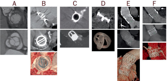
Examples of computer tomography images of prosthetic valves, including (A) biologic stented, (B) mechanical bileaflet tilting disc, (C) mechanical ball-in-cage, (D) mechanical single tilting disc, (E) transcatheter self-expandable, and (F) transcatheter balloon-expandable.
Prosthetic Valve Obstruction
Prosthetic valve obstruction is commonly caused by valve thrombosis or chronic fibrotic pannus formation usually in the subprosthetic area. Differentiation of pannus versus thrombus is outlined in Table 2.5,8 Rates of PV thrombosis and thromboembolism are higher for mechanical valves, especially in the early perioperative period, and higher for PVs in the mitral and right-sided positions.9–12 Suspected bioprosthetic PV thrombosis is defined as a 50% increase in prosthesis gradient within 5 years after implantation, increased cusp thickness, or abnormal cusp motion with a positive response to anticoagulation therapy (ie, a 50% decrease in prosthesis gradient).13–15 Structural valve failure is defined as the presence of marked pannus formation affecting the cusp motion, and it can often coexist with thrombus. In a large meta-analysis that included 217 patients with PV obstruction, 55.8% of them had pannus, 30.9% had thrombus, 9.8% had mixed pannus and thrombus, and 3.7% had other causes.16 Similar to surgical bioprosthetic PV, the risk for PV thrombosis complications after transcatheter aortic valve replacement (TAVR) is highest in the first 3 months after implantation.17 Clinical valve thrombosis after TAVR usually presents with elevated prosthetic gradients; however, subclinical thrombosis has been incidentally found on TEE and MDCT and is reported to be as high as 15% to 35%.4
Table 2.
Differentiation of etiology of prosthetic valve obstruction by pannus versus thrombus.
*timeframe from surgery; MV: mitral valve; AV: aortic valve; TV: tricuspid valve; INR: International Normalized Ratio; AF: atrial fibrillation/flutter; HU: Hounsfield units
| PANNUS | THROMBUS | |
|---|---|---|
| Timeframe* | ⩾ 12 mos, commonly ⩾ 5 yrs | Occurs at any timeframe (often mixed with pannus at later stages) |
| Valve location and type | MV > AV Mechanical = bioprosthetic |
TV > MV = AV Mechanical > bioprosthetic |
| Morphology | Fixed, small dense mass composed of fibrin material Bright echodensity Usually involve suture lines and subprosthetic location |
Mobile mass (usually larger than pannus) Soft echodensity Any location (usually supravalvular) |
| Clinical characteristics | ||
| INR | No effect | Increased risk with low INR (increased risk with AF and low cardiac output) |
| Symptoms | Insidious symptoms | Rapidly progressive symptoms, higher risk of stroke |
| Response to anticoagulation | No or minimal response | ⩾ 50% decrease in prosthesis gradient |
| CT HU attenuation | HU ⩾ 145 | HU ⩾ 90 |
Initial evaluation of suspected PV obstruction should be performed with TTE by assessing PV hemodynamics and comparing them to prior TTE if available. Three-dimensional TEE enables en-face visualization of the PV, especially in the mitral position, but has limited visualization of the aortic and right sided valves.18,19 MDCT has superior spatial resolution and can reconstruct in any valve plane, thereby enabling visualization of the prosthesis in any position with much less acoustic shadowing. Therefore, MDCT can be considered a second-line imaging test for identifying etiology of PV obstruction in mechanical or bioprosthetic (surgical or percutaneous) valves in the aortic, tricuspid, or pulmonic positions. MDCT can also characterize tissue for assessment of PV leaflet thickening, calcification, and thrombus.
Beam hardening artifact from mechanical valves can limit assessment of the periprosthetic area, although studies have shown solid differentiation of thrombus (90% CT versus 75% TEE) versus pannus (89% CT versus 62% TEE).16 The presence of a periprosthetic hypodense lesion on the inflow side of the PV (mechanical or bioprosthetic) is suggestive of pannus, whereas hypodensity on the outflow side is suggestive of thrombus (Figure 2).20 Several studies have shown higher Hounsfield unit (HU) attenuation for pannus HU ≥ 145 versus thrombus HU < 90, with a diagnostic accuracy of 87%.21–23 In TAVR, subclinical leaflet thrombosis has been incidentally found on MDCT and can be characterized as hypoattenuating leaflet thickening at the base of the leaflets, thus affecting leaflet motion in ECG-gated MDCT.4 Like fluoroscopy, 4D imaging with MDCT allows assessment of opening and closing angles of most commonly implanted bileaflet mechanical PVs to identify leaflet restriction or immobility; however, image quality is highly dependent on a good heart rate (ideally ≤ 60 beats per minute) and rhythm control.
Figure 2.
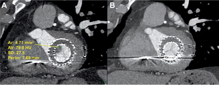
Transcatheter mitral valve prosthesis (A) with thrombus (HU < 90) noted on multidetector computed tomography and (B) with resolution of thrombus after anticoagulation on repeat computed tomography after 5 months. HU: Hounsfield units
Retrospective ECG gating without dose modulation to ensure optimal signal-to-noise ratio throughout the cardiac cycle should be performed for accurate 4D assessment of the prosthesis. Prosthetic valve leaflets with a residual opening angle > 20° and the presence of a periprosthetic hypodense lesion as visualized on MDCT suggests PV obstruction (Figure 3).20,24 MDCT also helps differentiate PVD from patient prosthesis mismatch, in which gradients are elevated due to a small valve orifice area relative to patient size with normal leaflet motion. Limited data is available on the use of MDCT in evaluating tricuspid or pulmonic prosthetic obstruction.16,20 Pulmonic valve dysfunction with use of the Melody valve has been reported in some cases of PV thrombosis.25–27
Figure 3.
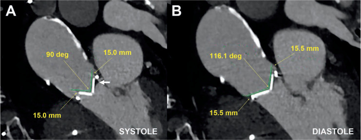
Multidetector computed tomography demonstrating (A) abnormal opening angle of 90° in systole and (B) normal closure in diastole in a patient with severe mechanical prosthetic aortic stenosis due to mixed pannus and thrombus (arrow).
Prosthetic Valvular Regurgitation
Mechanical or bioprosthetic PV regurgitation can occur in the setting of thrombus or pannus and cause incomplete valve coaptation, leading to valvular regurgitation and elevated gradients on TTE (Figure 4). Prosthetic valve thrombosis can also present with mixed obstruction and regurgitation, with up to 33% of bioprosthetic PV thrombosis presenting as mixed disease. Bioprosthetic valve degeneration presents with significant regurgitation more often than PV thrombosis due to reduced leaflet motion and calcification.2 Prosthetic valve endocarditis with complete or partial valve dehiscence can lead to paravalvular regurgitation. In TAVR, paravalvular regurgitation is usually a result of valve undersizing or calcium in the landing zone.28
Figure 4.
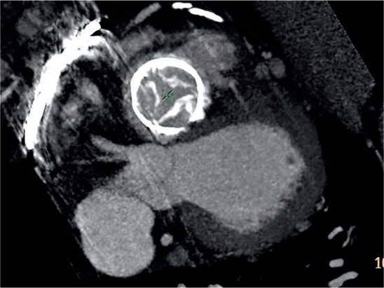
Degenerated bioprosthetic tricuspid valve with malcoaptation of calcified leaflets in systole resulting in severe tricuspid regurgitation.
Paravalvular leak (PVL) usually results from PV dehiscence due to the suture rings not being directly attached to surrounding cardiac structures or dehiscence due to endocarditis.20 Although visualization of a bioprosthetic mitral valve PVL using 3-dimensional (3D) TEE is good, it can be challenging in aortic prostheses due to acoustic shadowing. For mechanical or bioprostheses (surgical or percutaneous) in the mitral position, TTE followed by 3D TEE is often sufficient to identify severity and location of regurgitation. Since MDCT can reconstruct in any image plane, it can provide PVL localization in any prosthesis position, determine the defect size, and evaluate for PV dehiscence. Image quality is essential with proper contrast enhancement, and often TEE is needed to help initially localize the small PVL defect prior to MDCT. In mechanical valves, the use of MDCT to identify small PVL location may be challenging due to significant beam hardening artifact; therefore, combined TEE and MDCT is often needed to identify PVL defect and severity.
Unlike TTE or TEE, MDCT cannot provide flow velocity, hemodynamic assessment, or regurgitant quantification. Both 3D TEE and MDCT are useful in assessing PVL location and defect size and, in turn, guiding transcatheter PVL closure.29 MDCT is routinely used in pre-TAVR assessment of valve morphology, calcification, and aortic annulus sizing to minimize the risk of PVL.28 It also can provide similar anatomic assessment and evaluation of PV regurgitation etiology in tricuspid and pulmonic PV, although image acquisition will need to be optimized for adequate contrast opacification of right-sided structures. Because there is limited data on the use of MDCT to assess tricuspid or pulmonic PV regurgitation, TTE, TEE, or intracardiac echocardiography may be more suitable options for hemodynamic assessment in right-sided PV.
Cardiovascular magnetic resonance imaging (CMR) with phase contrast velocity mapping has been shown to be useful when quantifying eccentric regurgitation jets.30 The precision of CMR is superior to transthoracic echocardiography and could be used as an adjudicator of PVL severity. The use of CMR is helpful for quantification of valvular regurgitation, especially for eccentric PVL jets or when quantification by TEE is suboptimal, which can occur with transcatheter prosthesis and/or with multiple prosthetic devices. CMR quantification of PVL is related to outcomes depending on the regurgitant fraction.31,32
Prosthetic Valve Endocarditis
Prosthetic valve endocarditis can lead to PV obstruction, regurgitation from valve dehiscence, thickening/perforation of valve leaflets, abscess, fistula, pseudoaneurysm, or thromboembolic complications. Similar to thrombus, vegetations are low echogenic; they usually start on the valvular side of the prosthesis along the ring and spread to the leaflets, leading to leaflet malcoaptation and PVD. The risk of infective endocarditis after surgical or transcatheter valve replacement was found to be similar in prior studies.4 Independent of prosthesis type or location, TEE is preferred for initial assessment of PV endocarditis because it can identify and characterize size and vegetation mobility and assess for aortic root abscess and intracardiac fistula. Imaging with MDCT or CMR can provide additional information and identify anatomic complications related to endocarditis. In both mechanical and bioprosthetic valves, the presence of periprosthetic hypodensity on MDCT in the setting of annular abscess or PV dehiscence suggests endocarditis. The presence of a contrast-filled periprosthetic cavity that communicates with the cardiac chambers suggests pseudoaneurysm or fistula (Figure 5).2
Figure 5.
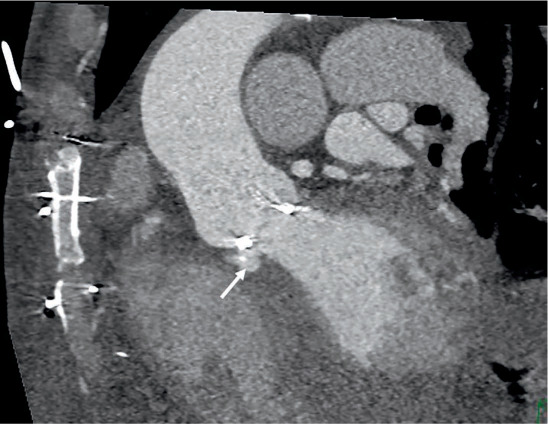
Prosthetic valve endocarditis complicated by prosthetic valve partial dehiscence and fistula between the aorta and left ventricle cavity (arrow).
Several studies have shown that MDCT is better at assessing mycotic aneurysm and abscess compared to TTE or TEE and provides additional relevant surgical information on aneurysm extent.33–35 Evaluation of right-sided PV endocarditis complications is possible with MDCT, keeping in mind the need for adequate contrast opacification and the potential challenge in assessing a mechanical prosthesis due to beam hardening. Endocarditis after TAVR or other percutaneous valve procedures is uncommon but can lead to significant mortality and morbidity, and the use of MDCT in this population is evolving.28,36,37 Positron emission tomography (PET) combined with CT using 18F-Fluorodeoxyglucose (18F-FDG) metabolic imaging can be used to evaluate active cardiac inflammation or infection.38 In a large meta-analysis, 18F-FDG PET/CT has been shown to have good diagnostic accuracy for PV endocarditis with 80.5% sensitivity and 73.1% specificity.39 PET/CT is an emerging useful diagnostic tool in evaluation of patients with PV endocarditis.
MANAGEMENT AND PROCEDURAL PLANNING FOR PROSTHETIC VALVE DYSFUNCTION
Transcatheter Valve-in-Valve Procedure for Prosthetic Valve Dysfunction
Patients who fail conservative medical therapy should be considered for percutaneous transcatheter VIV, device PVL closure, or redo surgical valve replacement. MDCT is the imaging modality of choice when planning VIV transcatheter aortic or mitral valve replacement (TMVR) procedures, the latter of which is only feasible in bioprosthetic surgical or TAVR valves. In any of these procedures, MDCT is useful for excluding PVL defects and left atrial appendage clots and can help with sizing of the prosthetic device and predicting adverse outcomes. For aortic or mitral VIV cases, either balloon-expandable (Edwards SAPIEN) or self-expandable (Medtronic CoreValve Evolut R) valves can be used depending on patient anatomy and valve location. The supra-annular Evolut R is preferred for aortic VIV given its superior hemodynamics compared to the intra-annular balloon-expandable SAPIEN valve. In these procedures, the type of PV dysfunction, valve sizing, risk of coronary obstruction, and need for balloon predilation are all considered for procedural planning. Though not routinely recommended due to upfront costs and the level of expertise needed, MDCT has been increasingly used to create 3D-printed models to simulate patient-specific PV geometry in specific high-risk transcatheter VIV cases; this enables accurate device sizing and prediction of potential complications between the PV and the implanted device.40,41
MDCT allows accurate measurement of the inner prosthesis diameter and perimeter/area and, therefore, accurate sizing of the VIV prosthesis. MDCT assessment of coronary ostial height (Figure 6) (height < 12 mm predicts higher risk of coronary obstruction), severe left ventricle outflow tract (LVOT) calcification (higher risk of aortic injury), aortic aneurysm, and size/burden of atherosclerotic disease further predicts the risk of adverse outcomes with an aortic VIV procedure.42 In patients with advanced renal disease, ECG-gated noncontrast MDCT may be helpful in assessing for aortic annular size and calcification. Free smart phone apps are now available for sizing for aortic and mitral VIV prostheses.
Figure 6.
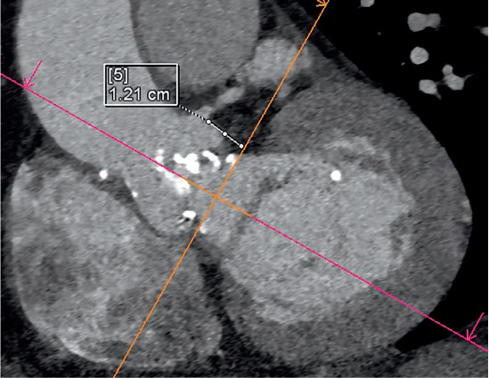
Multidetector computed tomography demonstrating measurement of the left coronary ostial height of 12 mm for planned aortic valve-in-valve procedure.
Mitral VIV or valve-in-ring have emerged as alternatives for high-risk patients. Using the mitral VIV application, a transcatheter heart valve (THV) is chosen based on sizing charts. Selecting the appropriate-sized device is important since an undersized THV can lead to device embolization while an oversized device can lead to THV distortion and LVOT obstruction. A simulation of the THV using a virtual THV can further confirm sizing and positioning of the device.43,44 With the virtual THV in place, the neo-LVOT area is determined. This is measured by the shortest area between the interventricular septum and the frame of the THV. Measurement of this area can be performed at different angles and depths of deployment to minimize the risk of LVOT obstruction.
The risk of LVOT obstruction varies and is lowest for VIV TMVR followed by valve-in-ring and highest for valve-in-mitral annular calcification. The risk is lower in cases where the anterior mitral leaflet has been previously resected. Several other predictors for LVOT obstruction have been identified, such as the aortomitral angle, length of anterior mitral leaflet, and ventricular geometry.45 A study by Wang et al. showed that a predicted neo-LVOT surface area of ≤ 189.4 mm2 had 100% sensitivity and 96.8% specificity for predicting TMVR-induced LVOT obstruction.46 The optimal phase of measuring the neo-LVOT may be patient specific; however, multiphase (specifically early systolic) assessment of the neo-LVOT may better determine risk of LVOT obstruction in TMVR.47 As previously shown, there is an overall 95% success rate for aortic and mitral VIV procedures. However, procedural success is patient specific and different across different structural interventions.42,45
Paravalvular Leak Closure
MDCT is a key imaging modality for anatomical characterization of PVL and can help localize a PVL defect by examining the entire circumference of the prosthetic ring on axial oblique image plane. This allows measurement of the anatomic regurgitant orifice area, which has shown good correlation with echocardiographic measurement.48 Currently, the Amplatzer Vascular Plug II (St. Jude Medical) is the most frequently used device in the United States for PVL closure, with several other devices used off label.49 Due to the morphological heterogeneity of various defects, operators must decide on the most compatible device. With its superior anatomical characterization and multiplanar formatting, MDCT helps determine the location, size, extent, defect course, and ideal closure device to optimize outcomes and minimize complications such as device embolization (Figure 7).
Figure 7.
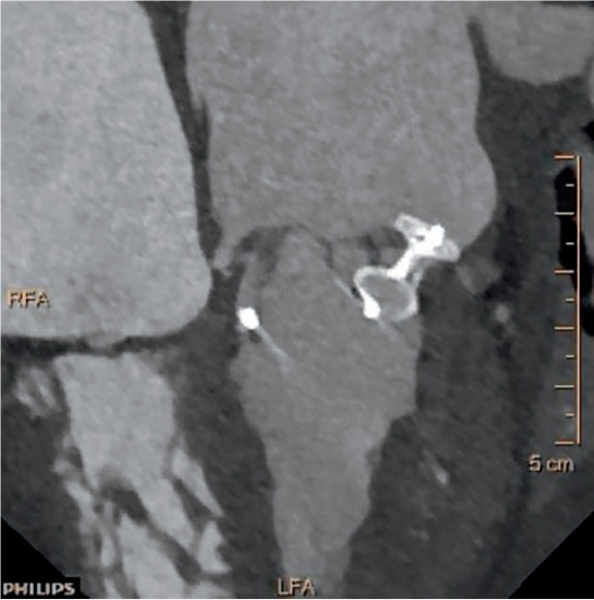
Multidetector computed tomography reconstruction for paravalvular leak (PVL) with subsequent PVL closure.
CT fusion imaging has been described in TAVR, PVL closure, and pulmonary vein stenting and can be an adjunctive tool for PVL closure planning.29,50 Preprocedural MDCT, which provides high-resolution 3D reconstruction images, is integrated with live fluoroscopic images that provide a visual road map of anatomical clues to help guide PVL closure (Figure 8). Overlaying 3D landmarks from MDCT on real-time fluoroscopy allows the operator to steer the catheter and device toward the target anatomical structure.51,52 Markers are placed on the fluoroscopy screen to aid in trans-septal puncture and defect localization.53 This approach also provides optimal angiographic angles to facilitate crossing the PVL defect, potentially reducing the amount of contrast used as well as total radiation exposure.52 Additionally, MDCT can also provide the fluoroscopic angle for guidewire crossing of the defect, which along with TEE guidance can facilitate PVL closure without the use of CT fusion imaging.
Figure 8.
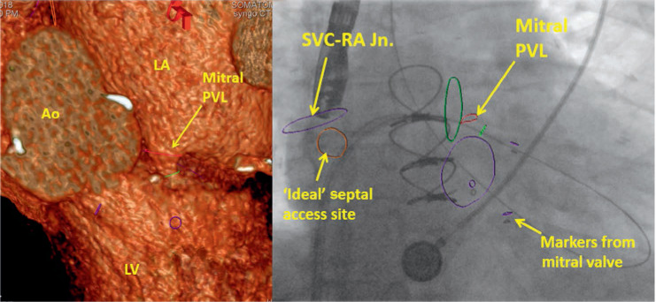
Multidetector computed tomography fusion imaging for planning of paravalvular leak closure. Ao: aorta; LV: left ventricle: LA: left atrium; PVL: paravalvular leak; SVC-RA Jn.: superior vena cava-right atrial junction
Surgical Planning for Prosthetic Valve Dysfunction
In addition to a comprehensive assessment of PVD, MDCT can facilitate preoperative surgical planning for redo valve surgery. A patient's individual risk can be determined by assessing the patency of coronary arteries and/or bypass grafts, prior surgical adhesions, aorta, extracardiac structures, and endocarditis complications and identifying high-risk features on MDCT. In particular, several high-risk cardiac structures must be considered before performing redo cardiac surgery, such as the right ventricle, innominate vein, aorta, or a prior coronary artery bypass graft crossing midline < 1 cm from the sternum.54 Other incidental findings on MDCT, such as cancer, pleural effusions, lung mass or consolidation, and carotid artery disease may have implications for adverse pre- and postoperative outcomes. MDCT not only provides superior anatomic detail but also may be safer and more cost effective, especially in high-risk patients or those with endocarditis and aortic root abscess.20
CONCLUSION
Diagnosis of PVD requires a high index of suspicion, a thorough review of clinical and imaging data, and in many cases a multimodality imaging approach (Figure 9).With its superior spatial resolution, MDCT allows accurate identification of PV obstruction due to thrombosis or pannus and localization of PVL defect to help guide closure. MDCT also plays an important role in preprocedural planning for transcatheter VIV and PVL closure with options for 3D-printed models and CT-fusion technology in high-risk clinical scenarios. Finally, MDCT allows coronary and extracardiac assessment to help determine risk for patients undergoing redo surgical valve replacement.
Figure 9.
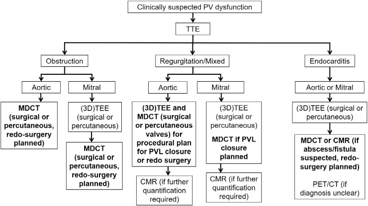
Role of multidetector computed tomography (MDCT) for management of patients with prosthetic valve dysfunction. TTE: transthoracic echocardiography; TEE: transesophageal echocardiography; CMR: cardiac magnetic resonance imaging; PVL: paravalvular leak; PET/CT: positron emission tomography/computed tomography
KEY POINTS
A multimodality approach is often needed to accurately diagnose and identify the etiology of prosthetic valve dysfunction.
Multidetector computed tomography (MDCT) allows accurate differentiation of prosthetic valve thrombosis and pannus formation and assesses complications from prosthetic valve endocarditis.
MDCT plays a key role in preprocedural planning and assessing risk for patients undergoing transcatheter device or surgical valve replacement.
Footnotes
Conflict of Interest Disclosure:
Dr. Mahmarian is a consultant for Astellas Pharma US.
REFERENCES
- 1.Suchá D, Symersky P, Tanis W et al. Multi-modality Imaging Assessment of Prosthetic Heart Valves. Circ Cardiovasc Imaging. 2015 Sep;8(9) doi: 10.1161/CIRCIMAGING.115.003703. e003703. [DOI] [PubMed] [Google Scholar]
- 2.Dangas GD, Weitz JI, Giustino G, Makkar R, Mehran R. Prosthetic Heart Valve Thrombosis. J Am Coll Cardiol. 2016 Dec 20;68(24):2670–89. doi: 10.1016/j.jacc.2016.09.958. [DOI] [PubMed] [Google Scholar]
- 3.Singh M, Sporn ZA, Schaff HV, Pellikka PA. ACC/AHA Versus ESC Guidelines on Prosthetic Heart Valve Management: JACC Guideline Comparison. J Am Coll Cardiol. 2019 Apr 9;73(13):1707–18. doi: 10.1016/j.jacc.2019.01.038. [DOI] [PubMed] [Google Scholar]
- 4.Sawaya F, Jørgensen TH, Søndergaard L, De Backer O. Transcatheter Bioprosthetic Aortic Valve Dysfunction: What We Know So Far. Front Cardiovasc Med. 2019 Oct 4;6:145. doi: 10.3389/fcvm.2019.00145. [DOI] [PMC free article] [PubMed] [Google Scholar]
- 5.Zoghbi WA, Chambers JB, Dumesnil JG et al. Recommendations for evaluation of prosthetic valves with echocardiography and doppler ultrasound: a report From the American Society of Echocardiography's Guidelines and Standards Committee and the Task Force on Prosthetic Valves, developed in conjunction with the American College of Cardiology Cardiovascular Imaging Committee, Cardiac Imaging Committee of the American Heart Association, the European Association of Echocardiography, a registered branch of the European Society of Cardiology, the Japanese Society of Echocardiography and the Canadian Society of Echocardiography, endorsed by the American College of Cardiology Foundation, American Heart Association, European Association of Echocardiography, a registered branch of the European Society of Cardiology, the Japanese Society of Echocardiography, and Canadian Society of Echocardiography. J Am Soc Echocardiogr. 2009 Sep;22(9):975–1014. doi: 10.1016/j.echo.2009.07.013. quiz 1082–4. [DOI] [PubMed] [Google Scholar]
- 6.Zoghbi WA, Asch FM, Bruce C et al. Guidelines for the Evaluation of Valvular Regurgitation After Percutaneous Valve Repair or Replacement: A Report from the American Society of Echocardiography Developed in Collaboration with the Society for Cardiovascular Angiography and Interventions, Japanese Society of Echocardiography, and Society for Cardiovascular Magnetic Resonance. J Am Soc Echocardiogr. 2019 Apr;32(4):431–75. doi: 10.1016/j.echo.2019.01.003. [DOI] [PubMed] [Google Scholar]
- 7.Habets J, Budde RP, Symersky P et al. Diagnostic evaluation of left-sided prosthetic heart valve dysfunction. Nat Rev Cardiol. 2011 May 17;8(8):466–78. doi: 10.1038/nrcardio.2011.71. [DOI] [PubMed] [Google Scholar]
- 8.Lancellotti P, Pibarot P, Chambers J et al. Recommendations for the imaging assessment of prosthetic heart valves: a report from the European Association of Cardiovascular Imaging endorsed by the Chinese Society of Echocardiography, the Inter-American Society of Echocardiography, and the Brazilian Department of Cardiovascular Imaging. Eur Heart J Cardiovasc Imaging. 2016 Jun;17(6):589–90. doi: 10.1093/ehjci/jew025. [DOI] [PubMed] [Google Scholar]
- 9.Roudaut R, Serri K, Lafitte S. Thrombosis of prosthetic heart valves: diagnosis and therapeutic considerations. Heart. 2007 Jan;93(1):137–42. doi: 10.1136/hrt.2005.071183. [DOI] [PMC free article] [PubMed] [Google Scholar]
- 10.Lin SS, Tiong IY, Asher CR, Murphy MT, Thomas JD, Griffin BP. Prediction of thrombus-related mechanical prosthetic valve dysfunction using transesophageal echocardiography. Am J Cardiol. 2000 Nov 15;86(10):1097–101. doi: 10.1016/s0002-9149(00)01166-8. [DOI] [PubMed] [Google Scholar]
- 11.Nishimura RA, Otto CM, Bonow RO et al. American College of Cardiology/American Heart Association Task Force on Practice Guidelines. 2014 AHA/ACC guideline for the management of patients with valvular heart disease: executive summary: a report of the American College of Cardiology/American Heart Association Task Force on Practice Guidelines. J Am Coll Cardiol. 2014 Jun 10;63(22):2438–88. doi: 10.1016/j.jacc.2014.02.537. [DOI] [PubMed] [Google Scholar]
- 12.Puvimanasinghe JP, Steyerberg EW, Takkenberg JJ et al. Prognosis after aortic valve replacement with a bioprosthesis: predictions based on meta-analysis and microsimulation. Circulation. 2001 Mar 20;103(11):1535–41. doi: 10.1161/01.cir.103.11.1535. [DOI] [PubMed] [Google Scholar]
- 13.Egbe AC, Connolly HM, Pellikka PA et al. Outcomes of Warfarin Therapy for Bioprosthetic Valve Thrombosis of Surgically Implanted Valves: A Prospective Study. JACC Cardiovasc Interv. 2017 Feb 27;10(4):379–87. doi: 10.1016/j.jcin.2016.11.027. [DOI] [PubMed] [Google Scholar]
- 14.Egbe AC, Pislaru SV, Pellikka PA et al. Bioprosthetic Valve Thrombosis Versus Structural Failure: Clinical and Echocardiographic Predictors. J Am Coll Cardiol. 2015 Dec 1;66(21):2285–94. doi: 10.1016/j.jacc.2015.09.022. [DOI] [PubMed] [Google Scholar]
- 15.Egbe A, Pislaru SV, Ali MA et al. Early Prosthetic Valve Dysfunction Due to Bioprosthetic Valve Thrombosis: The Role of Echocardiography. JACC Cardiovasc Imaging. 2018 Jul;11(7):951–8. doi: 10.1016/j.jcmg.2017.06.022. [DOI] [PubMed] [Google Scholar]
- 16.Kim JY, Suh YJ, Han K, Kim YJ, Choi BW. Diagnostic Value of Advanced Imaging Modalities for the Detection and Differentiation of Prosthetic Valve Obstruction: A Systematic Review and Meta-Analysis. JACC Cardiovasc Imaging. 2019 Nov;12(11 Pt 1):2182–92. doi: 10.1016/j.jcmg.2018.11.033. [DOI] [PubMed] [Google Scholar]
- 17.Stortecky S, Windecker S. Stroke: an infrequent but devastating complication in cardiovascular interventions. Circulation. 2012 Dec 18;126(25):2921–4. doi: 10.1161/CIRCULATIONAHA.112.149492. [DOI] [PubMed] [Google Scholar]
- 18.Gürsoy MO, Kalçik M, Karakoyun S, Özkan M. The current status of fluoroscopy and echocardiography in the diagnosis of prosthetic valve thrombosis-a review article. Echocardiography. 2015 Jan;32(1):156–64. doi: 10.1111/echo.12721. [DOI] [PubMed] [Google Scholar]
- 19.Ozkan M, Gürsoy OM, Astarcıoğlu MA et al. Real-time three-dimensional transesophageal echocardiography in the assessment of mechanical prosthetic mitral valve ring thrombosis. Am J Cardiol. 2013 Oct 1;112(7):977–83. doi: 10.1016/j.amjcard.2013.05.032. [DOI] [PubMed] [Google Scholar]
- 20.Chaikriangkrai K, Maragiannis D, Belousova T et al. Clinical Utility of Multidetector Computed Tomography in Redo Valve Procedures. J Card Surg. 2016 Mar;31(3):139–46. doi: 10.1111/jocs.12694. [DOI] [PubMed] [Google Scholar]
- 21.Gündüz S, Özkan M, Kalçik M et al. Sixty-Four-Section Cardiac Computed Tomography in Mechanical Prosthetic Heart Valve Dysfunction: Thrombus or Pannus. Circ Cardiovasc Imaging. 2015 Dec;8(12) doi: 10.1161/CIRCIMAGING.115.003246. [DOI] [PubMed] [Google Scholar]
- 22.Teshima H, Aoyagi S, Ueda T, Takagi K, Shojima T, Tanaka H. Evaluation of advancing the standard valve dysfunction by multidetector-row CT. J Artif Organs. 2014 Jun;17(2):162–8. doi: 10.1007/s10047-013-0751-z. [DOI] [PubMed] [Google Scholar]
- 23.Ueda T, Teshima H, Fukunaga S, Aoyagi S, Tanaka H. Evaluation of prosthetic valve obstruction on electrocardiographically gated multidetector-row computed tomography–identification of subprosthetic pannus in the aortic position. Circ J. 2013;77(2):418–23. doi: 10.1253/circj.cj-12-0290. [DOI] [PubMed] [Google Scholar]
- 24.Teshima H, Hayashida N, Fukunaga S et al. Usefulness of a multidetector-row computed tomography scanner for detecting pannus formation. Ann Thorac Surg. 2004 Feb;77(2):523–6. doi: 10.1016/S0003-4975(03)01531-5. [DOI] [PubMed] [Google Scholar]
- 25.Kellermair J, Gitter R, Mair R, Sigler M, Grund M, Steinwender C. First Report of an Acute, Obstructive Thrombosis of a Melody Valve Used for Transcatheter Pulmonary Replacement. Can J Cardiol. 2018 Dec;34(12):1688 e13–1688.e15. doi: 10.1016/j.cjca.2018.08.025. [DOI] [PubMed] [Google Scholar]
- 26.Schneider AE, Delaney JW, Cabalka AK. Non-infectious thrombosis of the melody((R)) valve: A tale of two cities. Catheter Cardiovasc Interv. 2016 Oct;88(4):600–604. doi: 10.1002/ccd.26339. [DOI] [PubMed] [Google Scholar]
- 27.Verhoeven PA, Learn CP, Brown NM, Goldstein BH. Noninfective Transcatheter Pulmonary Valve Thrombosis: A Rare Cause of Post-Implantation Pulmonary Valve Obstruction. JACC Cardiovasc Interv. 2017 Jul 10;10(13):e119–e122. doi: 10.1016/j.jcin.2017.04.009. [DOI] [PubMed] [Google Scholar]
- 28.Blanke P, Weir-McCall JR, Achenbach S et al. Computed tomography imaging in the context of transcatheter aortic valve implantation (TAVI)/transcatheter aortic valve replacement (TAVR): An expert consensus document of the Society of Cardiovascular Computed Tomography. J Cardiovasc Comput Tomogr. 2019 Jan-Feb;13(1):1–20. doi: 10.1016/j.jcct.2018.11.008. [DOI] [PubMed] [Google Scholar]
- 29.Malahfji M, Chang SM, Faza N et al. Clinical Utility of CT Fusion Imaging in Guiding Trans-catheter Paravalvular Leak Closure. Structural Heart. 2019 Jul;3:339–40. [Google Scholar]
- 30.Chai P, Mohiaddin R. How we perform cardiovascular magnetic resonance flow assessment using phase-contrast velocity mapping. J Cardiovasc Magn Reson. 2005;7(4):705–16. doi: 10.1081/jcmr-65639. [DOI] [PubMed] [Google Scholar]
- 31.Cavalcante JL, Lalude OO, Schoenhagen P, Lerakis S. Cardiovascular Magnetic Resonance Imaging for Structural and Valvular Heart Disease Interventions. JACC Cardiovasc Interv. 2016 Mar 14;9(5):399–425. doi: 10.1016/j.jcin.2015.11.031. [DOI] [PubMed] [Google Scholar]
- 32.Ribeiro HB, Orwat S, Hayek SS et al. Cardiovascular Magnetic Resonance to Evaluate Aortic Regurgitation After Transcatheter Aortic Valve Replacement. J Am Coll Cardiol. 2016 Aug 9;68(6):577–585. doi: 10.1016/j.jacc.2016.05.059. [DOI] [PubMed] [Google Scholar]
- 33.Fagman E, Perrotta S, Bech-Hanssen O et al. ECG-gated computed tomography: a new role for patients with suspected aortic prosthetic valve endocarditis. Eur Radiol. 2012 Nov;22(11):2407–14. doi: 10.1007/s00330-012-2491-5. [DOI] [PubMed] [Google Scholar]
- 34.Feuchtner GM, Stolzmann P, Dichtl W et al. Multislice computed tomography in infective endocarditis: comparison with transesophageal echocardiography and intraoperative findings. J Am Coll Cardiol. 2009 Feb 3;53(5):436–44. doi: 10.1016/j.jacc.2008.01.077. [DOI] [PubMed] [Google Scholar]
- 35.Habets J, Tanis W, van Herwerden LA et al. Cardiac computed tomography angiography results in diagnostic and therapeutic change in prosthetic heart valve endocarditis. Int J Cardiovasc Imaging. 2014 Feb;30(2):377–87. doi: 10.1007/s10554-013-0335-2. [DOI] [PubMed] [Google Scholar]
- 36.Regueiro A, Linke A, Latib A et al. Association Between Transcatheter Aortic Valve Replacement and Subsequent Infective Endocarditis and In-Hospital Death. JAMA. 2016 Sep 13;316(10):1083–92. doi: 10.1001/jama.2016.12347. [DOI] [PubMed] [Google Scholar]
- 37.Amat-Santos IJ, Ribeiro HB, Urena M et al. Prosthetic valve endocarditis after transcatheter valve replacement: a systematic review. JACC Cardiovasc Interv. 2015 Feb;8(2):334–46. doi: 10.1016/j.jcin.2014.09.013. [DOI] [PubMed] [Google Scholar]
- 38.Dilsizian V. Highlights from the Updated Joint ASNC/SNMMI PET Myocar-dial Perfusion and Metabolism Clinical Imaging Guidelines. J Nucl Med. 2016 Sep;57(9):1327–8. doi: 10.2967/jnumed.116.176214. [DOI] [PubMed] [Google Scholar]
- 39.Mahmood M, Kendi AT, Ajmal S et al. Meta-analysis of 18F-FDG PET/CT in the diagnosis of infective endocarditis. J Nucl Cardiol. 2019 Jun;26(3):922–35. doi: 10.1007/s12350-017-1092-8. [DOI] [PubMed] [Google Scholar]
- 40.Little SH, Vukicevic M, Avenatti E, Ramchandani M, Barker CM. 3D Printed Modeling for Patient-Specific Mitral Valve Intervention: Repair With a Clip and a Plug. JACC Cardiovasc Interv. 2016 May 9;9(9):973–5. doi: 10.1016/j.jcin.2016.02.027. [DOI] [PubMed] [Google Scholar]
- 41.Vukicevic M, Mosadegh B, Min JK, Little SH. Cardiac 3D Printing and its Future Directions. JACC Cardiovasc Imaging. 2017 Feb;10(2):171–84. doi: 10.1016/j.jcmg.2016.12.001. [DOI] [PMC free article] [PubMed] [Google Scholar]
- 42.Paradis JM, Del Trigo M, Puri R, Rodés-Cabau J. Transcatheter Valve-in-Valve and Valve-in-Ring for Treating Aortic and Mitral Surgical Prosthetic Dysfunction. J Am Coll Cardiol. 2015 Nov 3;66(18):2019–37. doi: 10.1016/j.jacc.2015.09.015. [DOI] [PubMed] [Google Scholar]
- 43.Bapat V. Valve-in-valve apps: why and how they were developed and how to use them. EuroIntervention. 2014 Sep;10(Suppl U):U44–51. doi: 10.4244/EIJV10SUA7. [DOI] [PubMed] [Google Scholar]
- 44.Guerrero M, Salinger M, Pursnani A et al. Transseptal transcatheter mitral valve-in-valve: A step by step guide from preprocedural planning to postprocedural care. Catheter Cardiovasc Interv. 2018 Sep 1;92(3):E185–E196. doi: 10.1002/ccd.27128. [DOI] [PubMed] [Google Scholar]
- 45.Yoon SH, Bleiziffer S, Latib A et al. Predictors of Left Ventricular Outflow Tract Obstruction After Transcatheter Mitral Valve Replacement. JACC Cardiovasc Interv. 2019 Jan 28;12(2):182–193. doi: 10.1016/j.jcin.2018.12.001. [DOI] [PubMed] [Google Scholar]
- 46.Wang DD, Eng MH, lGreenbaum AB et al. Validating a prediction modeling tool for left ventricular outflow tract (LVOT) obstruction after transcatheter mitral valve replacement (TMVR) Catheter Cardiovasc Interv. 2018 Aug 1;92(2):379–87. doi: 10.1002/ccd.27447. [DOI] [PubMed] [Google Scholar]
- 47.Meduri CU, Reardon MJ, Lim DS et al. Novel Multiphase Assessment for Predicting Left Ventricular Outflow Tract Obstruction Before Transcatheter Mitral Valve Replacement. JACC Cardiovasc Interv. 2019 Dec 9;12(23):2402–2412. doi: 10.1016/j.jcin.2019.06.015. [DOI] [PubMed] [Google Scholar]
- 48.Symersky P, Budde RP, de Mol BA, Prokop M. Comparison of multidetector-row computed tomography to echocardiography and fluoroscopy for evaluation of patients with mechanical prosthetic valve obstruction. Am J Cardiol. 2009 Oct 15;104(8):1128–34. doi: 10.1016/j.amjcard.2009.05.061. [DOI] [PubMed] [Google Scholar]
- 49.Alkhouli M, Rihal CS, Zack CJ et al. Transcatheter and Surgical Management of Mitral Paravalvular Leak: Long-Term Outcomes. JACC Cardiovasc Interv. 2017 Oct 9;10(19):1946–56. doi: 10.1016/j.jcin.2017.07.046. [DOI] [PubMed] [Google Scholar]
- 50.Krishnaswamy A, Tuzcu EM, Kapadia SR. Integration of MDCT and fluoroscopy using C-arm computed tomography to guide structural cardiac interventions in the cardiac catheterization laboratory. Catheter Cardiovasc Interv. 2015 Jan 1;85(1):139–47. doi: 10.1002/ccd.25392. [DOI] [PubMed] [Google Scholar]
- 51.Hascoet S, Smolka G, Bagate F et al. Multimodality imaging guidance for percutaneous paravalvular leak closure: Insights from the multi-centre FFPP register. Arch Cardiovasc Dis. 2018 Jun-Jul;111(6–7):421–31. doi: 10.1016/j.acvd.2018.05.001. [DOI] [PubMed] [Google Scholar]
- 52.Krishnaswamy A, Tuzcu EM, Kapadia SR. Three-dimensional computed tomography in the cardiac catheterization laboratory. Catheter Cardiovasc Interv. 2011 May 1;77(6):860–5. doi: 10.1002/ccd.22740. [DOI] [PubMed] [Google Scholar]
- 53.Kliger C, Eiros R, Isasti G et al. Review of surgical prosthetic paravalvular leaks: diagnosis and catheter-based closure. Eur Heart J. 2013 Mar;34(9):638–49. doi: 10.1093/eurheartj/ehs347. [DOI] [PubMed] [Google Scholar]
- 54.Kamdar AR, Meadows TA, Roselli EE et al. Multidetector computed tomographic angiography in planning of reoperative cardiothoracic surgery. Ann Thorac Surg. 2008 Apr;85(4):1239–45. doi: 10.1016/j.athoracsur.2007.11.075. [DOI] [PubMed] [Google Scholar]


