

Abstract
Flocking model has been widely used in robotic swarm control. However, the traditional model still has some problems such as manually adjusted parameters, poor stability and low adaptability when dealing with autonomous navigation tasks in large-scale groups and complex environments. Therefore, it is an important and meaningful research problem to automatically generate Optimized Flocking model (O-flocking) with better performance and portability. To solve this problem, we design Comprehensive Flocking (C-flocking) model which can meet the requirements of formation keeping, collision avoidance of convex and non-convex obstacles and directional movement. At the same time, Genetic Optimization Framework for Flocking Model (GF) is proposed. The important parameters of C-flocking model are extracted as seeds to initialize the population, and the offspring are generated through operations such as crossover and mutation. The offspring model is input into the experimental scene of autonomous navigation for robotic swarms, and the comprehensive fitness function value is obtained. The model with smallest value is selected as the new seed to continue evolution repeatedly, which finally generates the O-flocking model. The extended simulation experiments are carried out in more complex scenes, and the O-flocking and C-flocking are compared. Simulation results show that the O-flocking model can be migrated and applied to large-scale and complex scenes, and its performance is better than that of C-flocking model in most aspects.
Keywords: Robotic swarms, Flocking model, Multi-agent systems
Introduction
Robotic swarm system has been increasingly used in complex tasks, such as search and rescue [1], map drawing [2], target tracking [3], etc., which aims at keeping human beings away from the boring, harsh and dangerous environment. The simple local interaction among individuals in the system produces some new features and phenomena observed at the system level [4]. These laws are very similar to their biological counterparts, such as fish [5], bird [6], ant [7] and cell [8]. Flocking is one of the typical collective forms. This form is robust and flexible for the agents who join and exit, especially when there are obstacles, dangers, new tasks and other emergencies. Although flocking has many advantages, it still faces the problem of low performance caused by large scale, dynamic environment and other reasons. This phenomenon is more obvious in military projects, such as GREMLINS [9] and LOCUST [10], because of the worst working environment for large-scale UAVs which is small, low-cost and semi-autonomous.
Traditional flocking model is mainly designed according to the three principles of Reynolds: short-distance repulsion, middle-distance alignment and long-distance attraction [11]. Some researchers considered obstacle avoidance problems on flocking model. Wang et al. [12] proposed an improved fast flocking algorithm with obstacle avoidance for multi-agent dynamic systems based on Olfati-Sabers algorithm. Li et al. [13] studied the flocking problem of multi-agent systems with obstacle avoidance, in the situation when only a fraction of the agents have information on the obstacles. Vrohidis et al. [14] considered a networked multi-robot system operating in an obstacle populated planar workspace under a single leader-multiple followers architecture. Besides, previous works applied learning methods or heuristic algorithms on flocking model. The reinforcement learning (RL) method can adjust the movement strategy in time by exploring-using ideas, but its performance is not stable enough [15, 16]. Vásárhelyi et al. [17] considered the problems faced by the real self-organizing UAV cluster system and optimized the flocking model using evolutionary algorithm. Previous works improve the flocking model in several aspects, but it is still a challenge to automatically obtain a stable, scalable and portable flocking model for robotic swarm. The problems to be solved mainly include:
Harsh environment. In the actual environment, there may be different kinds of obstacles, including convex and non-convex ones. The traditional flocking model is difficult to deal with them easily.
Limited scale. Increasing scale of robotic swarm will bring new problems, such as frequent interactions, more conflicts and exceptions.
Parameter adjustment is difficult. Many parameters need to be set when designing the system model. The performance of group algorithm depends not only on expert experience, but also on scientific methods. Especially when there is correlation between parameters, it is difficult to get the optimal model quickly [11].
Previous work has not solved these problems comprehensively. In order to achieve better performance of robotic swarm in complex environment, C-flocking model is designed and O-flocking model is generated by GF framework. The main contributions of this paper are as follows:
We design the C-flocking model, which adds new obstacle avoidance strategies and directional movement strategy to the Reynolds’ flocking model [19].
We propose the Genetic Optimization Framework for Flocking Model (GF). The O-flocking model is obtained by this framework.
O-flocking model can be transferred from simple scene model to complex scene, from small-scale group to large-scale group. Through comparative analysis with C-flocking model, it is found that the comprehensive performance of O-flocking model is the best.
The rest of this paper is organized as follows: Sect. 2 analyzes the GF framework, where the C-flocking model, fitness function, and GF algorithm are introduced. Section 3 analyzes the experimental results. Summary and future work are introduced in Sect. 4.
Genetic Optimization Framework for Flocking Model
Through the analysis of previous researches, we find that it is necessary to automatically generate an optimized flocking model. So we propose GF framework. The input is C-flocking model and the output is O-flocking model, which meets the requirements of reliability, scalability and portability. As shown in Fig. 1, in GF architecture, it is generally divided into robot (agent) layer and environment layer, among which robot (agent) is divided into three layers, including sensor layer, decision layer and action layer, which support basic autonomous navigation functions. Through the rule generalization speed update formula described by the weight parameter, the weight parameter develops through the interaction with the environment. Environment is divided into two layers: evaluation layer and evolution layer. The former provides fitness function for the latter.
Fig. 1.
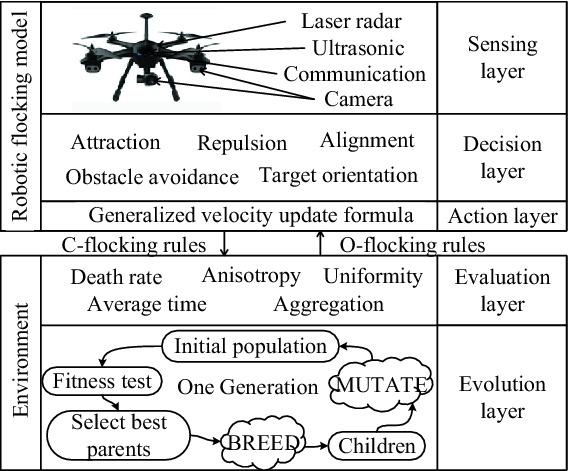
Genetic optimization framework for flocking model
C-Flocking Model for Robotic Swarm
In this section, we extend Reynold’s flocking model to C-flocking model, which simultaneously consider flocking-pattern maintenance, obstacle avoidance, and directional movements in its velocity updating formula.
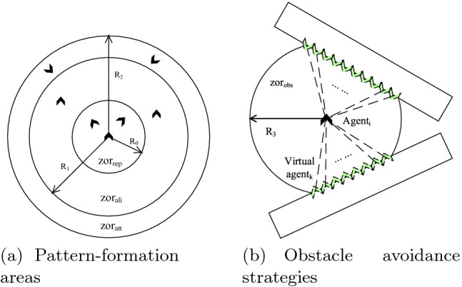
We assume that each agent of flocking moves through a square-shaped arena with a side length of , where convex and nonconvex obstacles appear. They need to pass through the arena quickly without death. If they hit each other or obstacles (including the walls), they disappear, which represents being dead in our simulation. As shown in Fig. 2, a robot agent i has three detection areas: exclusion area, alignment area, and attraction area. Among them, the exclusion zone is the circular zone with as radius, the alignment zone is the ring zone between and , the attraction zone is the ring zone between and . The arrow of the agent represents its speed direction, while the speed direction of other agents in different areas of the agent i is roughly affected as shown in Fig. 2(a).
Fig. 2.
C-flocking model for robotic swarm
If the distance between agents is under , agents will move in the opposite direction of each other’s connection:
| 1 |
where is the distance between agents i and j. and represent the position of agent i and j, respectively.
For pairwise alignment, we define the change of velocity relating to the difference of the velocity vectors of nearby agents [19].
| 2 |
In Eq. (2), is the velocity vector of agent j. is the number of agents in the area of alignment.
And for Long-range attraction, we define the term as follows:
| 3 |
In Eq. (3), is the distance between agents i and j. and represent the position of agent i and j.
For obstacle avoidance, we virtualize the surface of the obstacle towards robotic agent i into a series of robotic agents arranged as shown in Fig. 2(b). Each one of them will influence the velocity of robotic agent i. We define the change of velocity influenced by obstacles as follows:
| 4 |
where is the maximum range of obstacle detection for robotic agent i, and is the distance between agent i and virtual agent k. M is the number of the virtual agents.
For target orientation, we define the change of velocity influenced by target as follows:
| 5 |
In Eq. (5), is the distance between agents i and target. represents the position of target.
We take the sum of all delta velocity proposed above:
| 6 |
| 7 |
In Eq. (7), we define the weight parameters , which is used to flexibly handle the generalization formula.
If we consider the possible combinations of all constraints (each constraint can have two choices of Boolean values 0 and 1, which respectively represent the existence of the class constraint and the absence of the class constraint), then we can have a total of rules. Each rule should be designed according to expert experience. Through reference, design, analysis, and selection, we propose four main rules that can represent the main features of rules, which basically guarantees the performance of the flocking behavior of the robot cluster.
| 8 |
Tunning C-flocking model above means that we optimize the weight coefficient in the velocity Eq. (9). It is obvious that the parameter space is 20-dimensional, so manual adjustment of parameters will become very time-consuming.
The Genetic Algorithm for Model Evolution
Therefore, we propose genetic-flocking algorithm (GF) as the method for parameter tuning of flocking model. The specific operation is shown in Fig. 3:
1) Coding: The coding in this paper is based on natural number coding. Each chromosome has 20 DNA bits representing 20 parameters that require Parameter Tuning. The natural number coding is used for each DNA bit. The values are 0.1, 0.2, 0.3,.... 1. The specific encoding method is shown in the following figure:
2) Population Initialization: The method of population initialization adopts complete initialization. For each DNA bit in a chromosome, a value of 0.1 to 0.9 is generated and assigned to the chromosome referring to the C-flocking .
3) Cross-operation: This operation randomly selects two chromosomes in the population and randomly selects an equal length DNA segment on the two chromosomes for the exchange operation. The specific operation is as follows:
4) Mutation operation: Random mutation strategy is used in mutation operation. The strategy first chooses a random DNA site in a chromosome and randomly changes the value of the DNA site to another value. The value ranges from 0.1, 0.2, 0.3,... 1. The coefficient of variation was 0.5.
5) Selection Operations: Selection is performed in all the parents, offspring and mutants of the generation, and the individuals with the best evaluation results are selected to form the next generation’s father.
Fig. 3.

GA process and its application on flocking model
In the algorithm, the C-flocking’s rules are represented as: , and .
The outputs of GF algorithm are also a set of optimized rules: , and .
Fitness Function for Evaluation
In the GF algorithm, we propose fitness function, consisting of several evaluation indexes, to select the model with the best performance.
Average time is defined as the average time taken since the beginning of the navigation until the robotic swarm reaches the target area. Accordingly, we compute the Average time
| 9 |
where is the time when the navigation is triggered, and is the time when robotic agent j reaches the target area.
Death rate is described as the percentage of the robotic swarm being dead during the process of the navigation from the start area to the target area.
| 10 |
where represents the number of the dead agent, and represents the number of the total agents in the robotic swarm.
The centroid formula is
| 11 |
but the “quality" (homogeneity) of each agent is certain. Considering that the centroid is expressed by the average coordinate directly, then the average value of the relative distance between each step’s all points and the“centroid" is calculated, the aggregation and stability are analyzed, and these data are recorded, which can be used to analyze the changing rule of the two values in the whole process. Since our time is discrete, we can use discrete output to the aggregation formula of evolutionary algorithm:
| 12 |
where and are the abscissa and ordinate of the position of agent j, respectively. and are the abscissa and ordinate of the position of the swarm’s centroid at time t. T is the total time of the whole navigation process, while N is the agent number of the whole swarm.
We define the Uniformity of the robotic swarm as the variance of the sequence, which describes whether the flock structure of this swarm is stable.
| 13 |
| 14 |
We define anisotropic index to describe the variation of population velocity direction. Specifically, it needs to calculate the average angle of each individual velocity direction and flock velocity direction at a certain time, and then calculate the average value of the whole process, which is the index of anisotropic index. The variance of the average angle of the whole process represents the variation range of anisotropic index, and the formula of anisotropy is as follows:
| 15 |
| 16 |
In order to evaluate performance of models comprehensively, we firstly normalize the order parameters proposed above, and then define the global fitness function by the transfer function F(x).
| 17 |
With the following transfer function, we can construct a single objective fitness function that considering all necessary requirements. This function F can be used in the selection process of the GF algorithm.
| 18 |
Experiment Analysis
To reveal the performance improvements of O-flocking, we compare it with C-flocking from the aspect of the following six metrics in Table 1 including the order parameters and fitness function proposed above:
Table 1.
Comparisons between C-flocking & O-flocking with 20, 60 and 100 robots
| Evaluation | F | |||||||||||
|---|---|---|---|---|---|---|---|---|---|---|---|---|
| Algorithm | C–f | O–f | C–f | O–f | C–f | O–f | C–f | O–f | C–f | O–f | C–f | O–f |
| Num-20 | 0.85 | 0.47 | 38.69 | 5.31 | 130.05 | 84.50 | 0.29 | 0.01 | 0.35 | 0.00 | 6.11 | 0.01 |
| Num-60 | 0.86 | 0.43 | 42.82 | 4.69 | 128.7 | 83.92 | 0.32 | 0.04 | 0.33 | 0.00 | 7.61 | 0.037 |
| Num-100 | 1.17 | 0.46 | 50.15 | 4.99 | 115.80 | 84.25 | 0.21 | 0.03 | 2.74 | 0.00 | 92.82 | 0.03 |
Fitness function is the product of aggregation, anisotropy, average time, and uniformity. As a comprehensive evaluation index, fitness function plays an important role in our experiments. Besides, death rate is the basic constraint that must be considered when optimizing weight parameters of velocity formula, and it is also an evaluation index of the performance of each model. Experiments are performed on the computer with i7 processor, 8g memory and independent graphics card. The code for the related work has been put in [20]. The exact values of key parameters in our platform are as follows:
To find the performances differences, we apply C-flocking and O-flocking model in navigation experiment with three basic environmental elements including tunnel obstacle, non-convex obstacle and convex obstacle. As shown in Fig. 4, the C-flocking can complish the task basically, but they perform not good for their uniformity and stability. Meanwhile, our O-flocking model performs obviously better.
| 19 |
Equation (19) is the velocity updating formula of O-flocking. From analyzing the meaning of the velocity formula of C-flocking and O-flocking, we can analyze the following conclusions:
Whether obstacles are detected or not, we need to ensure that the obstacle avoidance coefficient in the formula keeps a larger value, which also proves that the obstacle avoidance strategy plays an important role in the completion of the whole task.
In any case, it is important to ensure that all factors are taken into account at the same time, which is reflected in the formula without taking zero as the value of parameters.
The parameters of the velocity formula are related to the order parameters of the fitness function. The alignment, attraction and the target orientation parameters (b, c, and e) are always kept at a higher value. Through analysis, it is found that this is related to the fitness function we set up. The time is related to the target orientation coefficient. Also, the aggregation, anisotropy and uniformity are all related to the alignment and attraction coefficients. We set the threshold (0.2) of the swarm death rate as the constraints, which is mainly related to obstacle avoidance parameters (d), so the repulsion parameters (a) has little influence on the whole system. So it seems that the regulations of a are contrary to common sense. For example, when there is an individual in the repulsion area, the repulsion coefficient a is smaller.
Fig. 4.

C-flocking and O-flocking traces of the robotic swarm in autonomous navigation in complex environment (We tested 3 groups of experiments using 20, 60 and 100 robotic agents for simulation.)
Figure 4 shows directly that O-flocking performs better than C-flocking in uniformity and stability. Figure 4(a) and Fig. 4(b) represent the performance of these two model with 20 robotic agents, Fig. 4(c) and Fig. 4(d) with 60 robots, Fig. 4(e) and Fig. 4(f) with 100 robots. Obviously, with the increasing quantity, the performance of C-flocking is obviously getting worse and worse, while O-flocking is getting better and better.
Specific performance indicators are shown in Table 1. C–f represents the C-flocking model, while O–f represents the O-flocking model. We record the values of each evaluation index of the two models in three situations of the number and scale of robots. Generally, all the indicators of O-flocking model perform better (the smaller, the better). Specifically, aggregation of O-flocking is 56% lower than that of C-flocking while the reduction of other indicators (anisotropy, average time, uniformity, death rate, and fitness function) are 88.61%, 32.55%, 89.69%, 100%, and 99.92%, respectively.
Figure 5 shows the change of uniformity in the whole time step. The total time step of each group of experiments is not the same, but it can be seen from the figure that the data of each group of O-flocking are stable between 0 and 1, which means that the stability and tightness of the cluster are very good during the whole cruise. When C-flocking passes through obstacles, it can be seen that there will be large fluctuations near step 31 and step 71. Such fluctuations represent the situation of low cluster tightness and stability when cluster passes through narrow and non-convex obstacles, and the formation is not well maintained. At the same time, it can be seen that O-flocking has completed the whole task in about 84 s, while C-flocking has not completed the whole task.
Fig. 5.

The uniformity of the robotic swarm with each experiment changes through time.
Conclusions and Future Work
We presented in this paper an optimized flocking model for robotic swarm in autonomous navigation, that is O-flocking. This model is obtained through GF framework proposed by us, which is the combination of the genetic algorithm and robotic flocking model. This work comprehensively addresses the reliability, adaptivity and scalability of the robotic swarm during completing the navigation tasks. Also, we provide a simple way of thinking for robot researchers or users to solve problems. Only by building a simple model for a specific task and environment and abstracting the speed formula of the robot, we can quickly get a solution with superior performance. This greatly reduces the workload of manual parameter adjustment and improves the efficiency of task completion.
Our future works are as follows: First, we will extend our experiment to the real-world systems such as unmanned aerial systems and unmanned ground systems. Second, we will take more uncertainties of sceneries into the model to verify the correctness of our model, such as adding the moving obstacle, the irregular barriers, and even fluid barriers. Third, we consider allowing the system to evolve new rules on its own in an incomplete information environment, which is more in line with the actual scenario.
Acknowledgments
This work was supported by the National Natural Science Foundation of China 61872378, Research and Innovation Project for Graduate Students in Hunan Province CX2018B021, and the Scientific Research Project of National University of Defense Technology through grant ZK19-03.
Contributor Information
Ying Tan, Email: ytan@pku.edu.cn.
Yuhui Shi, Email: shiyh@sustc.edu.cn.
Milan Tuba, Email: tuba@np.ac.rs.
Li Ma, Email: 18874857546@163.com.
Weidong Bao, Email: wdbao@nudt.edu.cn.
Xiaomin Zhu, Email: xmzhu@nudt.edu.cn.
Meng Wu, Email: wumeng15@nudt.edu.cn.
Yuan Wang, Email: wy1020395067@hotmail.com.
Yunxiang Ling, Email: 2923821396@qq.com.
Wen Zhou, Email: zhouwen@nudt.edu.cn.
References
- 1.Murphy RR, et al. Search and rescue robotics. In: Siciliano B, Khatib O, et al., editors. Springer Handbook of Robotics. Heidelberg: Springer; 2008. pp. 1151–1173. [Google Scholar]
- 2.Dirafzoon, A., Lobaton, E.: Topological mapping of unknown environments using an unlocalized robotic swarm. In: IEEE/RSJ International Conference on Intelligent Robots & Systems. IEEE (2014)
- 3.Parker LE. Multiple Mobile Robot Systems. In: Siciliano B, Khatib O, editors. Springer Handbook of Robotics. Heidelberg: Springer; 2008. pp. 921–941. [Google Scholar]
- 4.Brown, D.S., Kerman, S.C., Goodrich, M.A.: Human-swarm interactions based on managing attractors. In: Proceedings of the 2014 ACM/IEEE International Conference on Human-Robot Interaction - HRI 2014, 3–6 March 2014, pp. 90–97. ACM Press, Bielefeld (2014)
- 5.Krause J, Hoare D, Krause S, Hemelrijk CK, Rubenstein DI. Leadership in fish shoals. Fish Fish. 2015;1(1):82–89. doi: 10.1111/j.1467-2979.2000.tb00001.x. [DOI] [Google Scholar]
- 6.Nagy M, Ákos Z, Biro D, Vicsek T. Hierarchical group dynamics in pigeon flocks. Nature. 2010;464(7290):890–893. doi: 10.1038/nature08891. [DOI] [PubMed] [Google Scholar]
- 7.Feinerman O, Pinkoviezky I, Gelblum A, Fonio E, Gov NS. The physics of cooperative transport in groups of ants. Nat. Phys. 2018;14(7):683–693. doi: 10.1038/s41567-018-0107-y. [DOI] [Google Scholar]
- 8.Cheung KJ, Gabrielson E, Werb Z, et al. Collective invasion in breast cancer requires a conserved basal epithelial program. Cell. 2013;155(7):1639–1651. doi: 10.1016/j.cell.2013.11.029. [DOI] [PMC free article] [PubMed] [Google Scholar]
- 9.Husseini, T.: Gremlins are coming: DARPA enters Phase III of its UAV programme (2018). https://www.army-technology.com/features/gremlins-darpa-uav-programme/
- 10.Raytheon gets $29m for work on US Navy LOCUST UAV prototype. https://navaltoday.com/2018/06/28/raytheon-wins-contract-for-locus-inp/
- 11.Eversham, J., Ruiz, V.F.: Parameter analysis of reynolds flocking model. In: 2010 IEEE 9th International Conference on Cybernetic Intelligent Systems. IEEE (2010)
- 12.Wang J, Xin M. Flocking of multi-agent system using a unified optimal control approach. J. Dyn. Syst. Meas. Control. 2013;135(6):061005. doi: 10.1115/1.4024903. [DOI] [Google Scholar]
- 13.Li J, Zhang W, Su H, Yang Y. Flocking of partially-informed multi-agent systems avoiding obstacles with arbitrary shape. Auton. Agents Multi-Agent Syst. 2014;29(5):943–972. doi: 10.1007/s10458-014-9272-2. [DOI] [Google Scholar]
- 14.Vrohidis C, Vlantis P, Bechlioulis CP, Kyriakopoulos KJ. Reconfigurable multi-robot coordination with guaranteed convergence in obstacle cluttered environments under local communication. Auton. Robots. 2017;42(4):853–873. doi: 10.1007/s10514-017-9660-y. [DOI] [Google Scholar]
- 15.Ueyama A, Isokawa T, Nishimura H, Matsui N. A comparison of grouping behaviors on rule-based and learning-based multi-agent systems. In: Suzuki Y, Hagiya M, editors. Recent Advances in Natural Computing; Tokyo: Springer; 2016. pp. 27–40. [Google Scholar]
- 16.Morihiro K, Matsui N, Isokawa T, Nishimura H. Reinforcement learning scheme for grouping and characterization of multi-agent network. In: Setchi R, Jordanov I, Howlett RJ, Jain LC, editors. Knowledge-Based and Intelligent Information and Engineering Systems; Heidelberg: Springer; 2010. pp. 592–601. [Google Scholar]
- 17.Vásárhelyi, G., Virágh, C., et al.: Optimized flocking of autonomous drones in confined environments. Sci. Robot. 3(20), eaat3536 (2018) [DOI] [PubMed]
- 18.Guilherme Henrique Polo Goncalves: simulando movimento de bando de passáros em javascript, Github (2010). https://github.com/gpolo/birdflocking/blob/master/doc/artigo.pdf
- 19.Braga RG, da Silva RC, Ramos ACB, Mora-Camino F. Collision avoidance based on reynolds rules: a case study using quadrotors. In: Latifi S, editor. Information Technology - New Generations; Cham: Springer; 2018. pp. 773–780. [Google Scholar]
- 20.https://github.com/Downloadmarktown/Flocking-experiment-platform