

Abstract
The secular dynamics of a non-relativistic charged particle in an electromagnetic wave can be described by the ponderomotive potential. Although ponderomotive electron-laser interactions at relativistic velocities are important for emerging technologies from laser-based particle accelerators to laser-enhanced electron microscopy, the effects of special relativity on the interaction have only been studied theoretically. Here, we use a transmission electron microscope to measure the position-dependent phase shift imparted to a relativistic electron wave function when it traverses a standing laser wave. The kinetic energy of the electrons is varied between 80 keV and 300 keV, and the laser standing wave has a continuous-wave intensity of 175 GW/cm2. In contrast to the non-relativistic case, we demonstrate that the phase shift depends on both the electron velocity and the wave polarization, confirming the predictions of a quasiclassical theory of the interaction. Remarkably, if the electron’s speed is greater than of the speed of light, the phase shift at the electric field nodes of the wave can exceed that at the antinodes. In this case there exists a polarization such that the phase shifts at the nodes and antinodes are equal, and the electron does not experience Kapitza-Dirac diffraction. Our results thus provide new capabilities for coherent electron beam manipulation.
The motion of a non-relativistic charged particle in an electromagnetic (EM) wave can be described on time scales longer than the wave period by the ponderomotive potential [1], an effective potential proportional to the time-averaged square of the electric field and independent of the EM wave polarization or particle velocity. The ponderomotive potential plays an important role in a variety of phenomena including the Kapitza-Dirac effect [2, 3], high-harmonic generation [4], laser-driven particle acceleration [5], free electron laser seeding [6], electron pulse train generation [7, 8], and laser-controlled electron interferometry [9–11].
A significant theoretical effort has been dedicated to generalizing the ponderomotive potential for particles with relativistic initial velocities [12–17]. In this case, the interaction depends on both the particle velocity and EM wave polarization. While non-relativistic particles are always pushed away from the high electric field amplitude regions of the wave, relativistic particles can be deflected towards them, in an effect called relativistic reversal [14]. This effect enables polarization-based control of the coherent manipulation of relativistic electron beams using laser light, with applications including rapidly-switchable electron beamsplitters, Kapitza-Dirac diffraction-free phase shifters, and ponderomotive free-electron laser wigglers [12, 18].
Here, we experimentally study the interaction of a relativistic electron with a standing laser wave. We first formulate a quasiclassical theory of the interaction which allows us to calculate the phase shift imparted to an electron wavepacket as it traverses the laser wave, from which modifications to the ponderomotive potential can be derived. Then, using the relativistic electron beam of a transmission electron microscope (TEM) and the standing laser wave of a Fabry-Pérot optical cavity, we image the phase shift imparted to the electron beam and observe velocity- and polarization-dependent relativistic effects including relativistic reversal.
To calculate the phase shift imparted to a relativistic charged particle by an EM wave of arbitrary spatial and temporal configuration, we use the quasiclassical approximation, which assumes that the shortest wavelength present in the EM wave λL is much larger than the electron wavelength λe. This condition is satisfied in most experimentally relevant situations. The phase shift is then given by the action along the classical trajectory divided by the reduced Planck constant ħ. We perform this calculation up to second order in the electric field strength, which in the quantum picture corresponds to stimulated Compton scattering (SCS) [2, 19]. This approximation is valid over a wide range of EM wave intensities, from an onset where SCS overcomes spontaneous Compton scattering [2], up to the “relativistic” wave intensity [20, 21] where the particle is accelerated to a relativistic velocity within a single cycle of the wave.
Since the action is a Lorentz scalar, it is convenient to perform the calculations in the reference frame co-moving with the initial (unperturbed) velocity of the electron, , where the motion remains non-relativistic at all times. β is the electron’s speed in units of the speed of light c. Variables in the co-moving frame are denoted by an apostrophe. The phase shift can then be written as
| 1 |
where m is the electron mass, e is the elementary charge, and A′ (r′ (t′) , t′) is the vector potential (in the Coulomb gauge) evaluated at the electron’s position r′ (t′). We evaluate this expression perturbatively to the leading (second) order in the field strength parameter e |A′| /mc. The first order contribution to the phase shift vanishes due to energy-momentum conservation. In the co-moving frame, the electron is initially at rest at position . The electric field of the EM wave accelerates it to a velocity which, to first order in e |A′| /mc, is given by . Using this expression in Eq. (1), the phase can then be expressed (to second order in e |A′| /mc) in terms of only A′:
| 2 |
To express the phase shift in terms of the laboratory frame Coulomb gauge vector potential, we perform a Lorentz transformation and then restore the Coulomb gauge by a gauge transformation (see supplementary materials). The resulting expression is
| 3 |
where r0 (t) is the unperturbed electron trajectory in the laboratory frame, γ = 1 − β2)− 1/2, and
| 4 |
is the gauge function, and x = (x, y, z). Using the slowly-varying envelope approximation, which assumes that the amplitude of the EM wave varies slowly along the electron trajectory relative to its oscillation period, we can time-average the integrand of Eq. (3) over one cycle of the field, leaving an effective potential. To zeroth order in β, this potential is simply the ponderomotive potential , where the angle brackets denote a time-average over one oscillation period of the field. We note, however, that Eq. (3) remains valid in general for the SCS phase shift, even if the electromagnetic field does not have a slowly-varying envelope in time and space.
When the electron is relativistic, the β-dependent terms in Eq. (3) cannot be neglected. In particular, the ∇G terms become relevant if the amplitude of the EM wave varies substantially over distances comparable to its wavelength, such as in a standing wave. In the case of a monochromatic standing wave with its wavevector parallel to the x-axis and polarization specified by angle θ and ellipticity parameter ϵ, the Coulomb gauge vector potential can be written as
| 5 |
where A0 (y, z) is the wave’s amplitude envelope and ω = 2πc/λL is its angular frequency. If the slowly-varying envelope approximation is satisfied, time-averaging the integrand of Eq. (3) results in the relativistic effective potential
| 6 |
where
| 7 |
describes the relative depth of the standing wave structure of the potential. An electron beam passing through such an EM wave will acquire a spatial phase modulation
| 8 |
| 9 |
where ϕ0 (0) ρ (θ, β) is the depth of the phase modulation along the wave axis.
Equation (6) and Eq. (7) show that the relativistic interaction is strongly dependent on both the electron speed β and EM wave polarization angle θ, though not on the ellipticity parameter ϵ. Importantly, if , there exists a polarization angle θr, referred to as the relativistic reversal angle [14], such that ρ (θr, β) = 0. At this angle, the standing wave structure of the phase shift disappears entirely, and therefore no Kapitza-Dirac diffraction occurs.
The relativistic interaction also modifies the laser-induced group delay of the electron wave function. The group delay, equivalent to the retardation of a classical particle and defined as , can be calculated from the energy dependence of the electron phase shift:
| 10 |
| 11 |
In particular, at θ = θr, when the standing-wave structure in the potential of Eq. (6) vanishes, the standing wave structure is still present in the spatial profile of the group delay. Furthermore, when , the group delay is negative for portions of the standing wave around the electric field nodes. This negative group delay corresponds to an attractive potential, in contrast to the non-relativistic ponderomotive potential which is always repulsive.
A schematic of the experiment is shown in Fig. 1(a). The electron beam of a TEM (Thermo Fisher Scientific Titan) passes through a standing laser wave, where the axis of the standing wave is perpendicular to the propagation direction of the electron beam . The interaction imprints a spatial phase modulation on the electron wave function, as described by (Eq. 8). The electron beam then propagates away from the interaction region before it is imaged using a direct electron detection camera (Gatan K2) [22]. The electron beam is brought to a focus before it crosses the standing laser wave such that a point-projection image, known as a “Ronchigram,” is formed on the camera [23, 24]. As illustrated in Fig. 1(b), paraxial propagation of the electron beam from the interaction region to the camera partially converts the phase modulation of the electron wave function to amplitude modulation, allowing the phase modulation to be imaged. The electron’s kinetic energy K = (γ − 1) mc2 can be adjusted between 80 keV and 300 keV by changing the TEM’s accelerating voltage.
Figure 1.
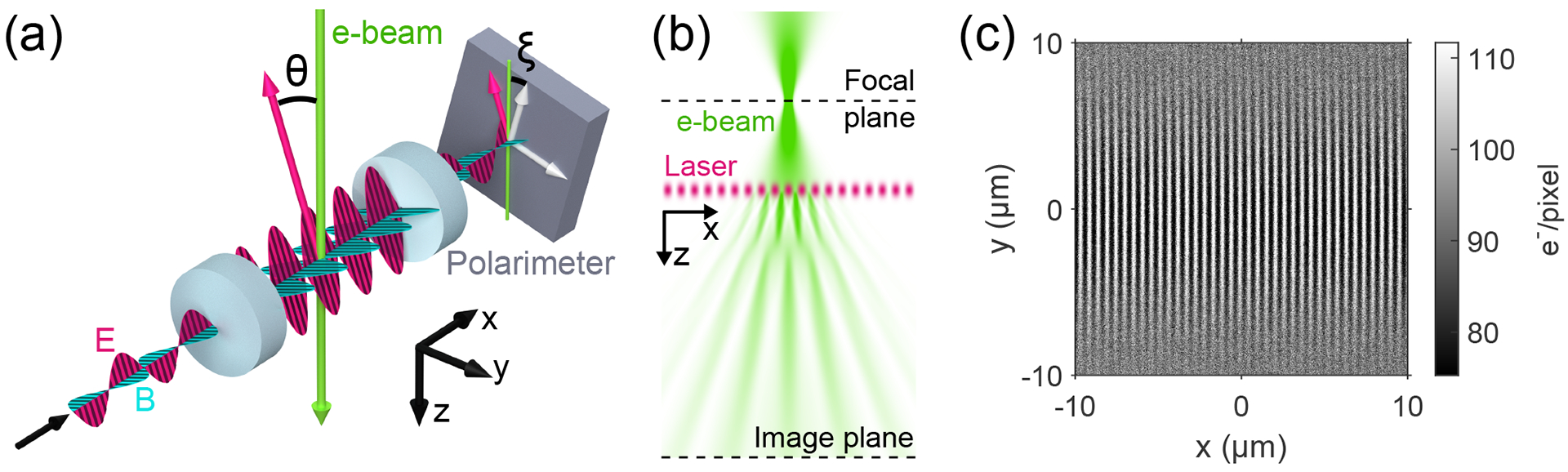
a) Schematic. An electron beam intersects a standing laser wave (electric field shown in magenta, magnetic field shown in cyan) formed between the two mirrors (blue cylinders) of a Fabry-Pérot optical cavity. The dimensions of the cavity are not shown to scale. The polarization axis of the standing wave (magenta arrows) makes an angle θ with the electron beam axis. The polarimeter is tilted by an angle ξ relative to the electron beam axis. b) Phase modulation detection scheme. The electron beam crosses the standing laser wave after passing through a focus. The interaction with the standing wave imprints a spatial phase modulation on the electron beam which is converted to intensity modulation as the electron beam propagates to the image plane. c) Ronchigram of the standing laser wave. The direct electron detection camera records the number of electrons landing on each of its pixels. In the image plane, the standing wave structure of the phase modulation manifests as a series of bright and dark fringes.
The standing laser wave is formed inside of a Fabry-Pérot optical cavity which serves to amplify and focus a continuous-wave laser beam with a wavelength of λL = 1064 nm [9–11]. The fundamental mode of the cavity has a Gaussian profile such that at its waist where it intersects the electron beam, Eq. (9) gives
| 12 |
where w0 is the 1/e2 radius of the mode, α is the fine-structure constant, and P is the optical power circulating in the cavity. Since a relativistic electron spends little time interacting with the EM wave, the laser intensity must be high in order for the electron wave function to accumulate appreciable phase. We achieve phase shifts on the order of 1 rad with a circulating power of 44 kW focused to a w0 = 8 μm focus, corresponding to a peak standing wave intensity of 175 GW/cm2. To our knowledge, this is the highest continuous-wave laser intensity ever achieved.
A half-wave plate placed at the input of the optical cavity is used to control the linear polarization angle of the light entering the cavity. A portion of the light transmitted through the cavity is sent to a polarimeter which measures the optical power in the two orthogonal polarization components relative to the polarimeter axis. The polarimeter employs polarizing beamsplitter cubes to separate the orthogonal polarization components, and calibrated photodiodes to measure the optical power of each component (see supplementary materials). The absolute value and sign of the polarization angle θ are determined from the polarimeter reading and orientation of the half-wave plate, respectively. The polarization at the polarimeter is assumed to be the same as that inside the cavity, as the cavity was measured to not appreciably change the polarization between its input and output (see supplementary materials).
Ronchigrams were collected at electron beam energies of K = 80, 150, 215, 230, 245, 260, 275, 290, and 300 keV. At each electron energy the rotation angle of the half-wave plate was incremented between 10 s electron camera exposures. The half-wave plate was rotated through 90° in one direction and then rotated back to the original position, thereby rotating the polarization angle from θ ≈ −90° to θ ≈ +90° and back again. Rotation of the polarization angle through a full 180° allowed for the determination of any misalignment between the polarimeter axis and the electron beam axis (angle ξ shown in Fig. 1(a)).
Figure 1(c) shows a typical unprocessed Ronchigram. Both the standing wave structure and the transverse Gaussian profile of the cavity mode are clearly evident. Each Ronchigram was fit in Fourier space using the phase modulation depth of the standing wave as a fit parameter (see supplementary materials). To correct for small variations in the laser wave parameters during the experiment, the phase modulation depth was normalized by the optical power at the polarimeter (proportional to the circulating power P) and the mode waist w0, which were both measured at the time the Ronchigram was taken. The mode waist was determined from a measurement of the cavity’s transverse mode frequency spacing (see supplementary materials). The fractional change in λL during a typical experiment was measured to be small enough (~ 10−6) that it was assumed to be constant for the purpose of normalization.
Each set of normalized modulation depth versus polarization angle data was fit to Eq. (7), with an angle-independent normalization constant, a polarization angle axis o set, and the electron speed β as fit parameters. The electron speed was used as a fit parameter because the nominal electron energies K are only accurate to approximately ±1% (per the TEM manufacturer’s specifications). The polarization angle axis o set accounts for the polarimeter misalignment angle ξ, as well as any linear polarization rotation induced by optics between the cavity output and polarimeter (see supplementary materials).
This data is presented in Fig. 2(a); for clarity, only the K = 80, 150, 215, and 300 keV data sets are shown. The remaining data sets are shown in the supplementary materials. The relative phase modulation depth exhibits a dependence on the polarization angle θ that is well-modeled by (Eq. 7); the root-mean-squared difference between the fit and data across all data sets is 7.1 × 10⁻³. To show the relative phase modulation depth’s β-dependence, the fit values at θ = 0 are plotted as a function of the nominal values of β2 for all data sets in Fig. 2(b), where they are compared with the linear dependence expected from (Eq. 7). Again, there is a good correspondence between the measured values and theoretical model.
Figure 2.

a) Relative phase modulation depth as a function of polarization angle. Measurements of the relative phase modulation depth (dots) are plotted along with fitted theory curves (lines) as a function of the laser wave polarization angle θ for several values of the nominal electron energy K (equivalently, electron speed β). The fitted theory (solid lines) is described by Eq. (7). b) Relative phase modulation depth as a function of electron speed. Fit values for the relative phase modulation depth at θ = 0 are shown as a function of β2 for each of the nine electron energies examined (black dots). The theoretical dependence on β2 predicted by Eq. (7) is shown in red. c) Relativistic reversal. Ronchigram standing wave fringes are shown as a function of polarization angle θ and position along the laser beam axis x for the K = 300 keV data set used in panel (a). The bright (red) and dark (blue) fringes reverse positions around the relativistic reversal angle θr (horizontal black line). The vertical lines are a guide-to-eye.
Imaging of the spatial phase modulation profile allows the relativistic reversal effect to be directly observed in the Ronchigrams. As the polarization angle is rotated through the relativistic reversal angle, the standing wave structure in the Ronchigram diminishes in amplitude until it disappears entirely and then re-emerges with the opposite sign. This is demonstrated in Fig. 2(c), using Ronchigrams from the K = 300 keV data set shown in Fig. 2(a). A temporally linear drift in the fringe position of 0.4 nm/s due to thermal expansion of the cavity support structure has been removed from the displayed data (see supplementary materials). The change in fringe position around θr was used to infer the sign of the relative phase modulation depth for the K ≥ 215 keV data sets in Fig. 2(a) and Fig. 2(b).
Our results show that SCS of relativistic particles exhibits a strong dependence on the electron velocity and the EM wave polarization, and that this dependence is well-described by a quasiclassical theory of the interaction. The most striking feature of the polarization dependence is that the standing wave structure of the phase shift reverses its sign at a particular polarization angle when . Therefore, this experiment can also be understood as an observation of the relativistic reversal of the amplitude of Kapitza-Dirac diffraction [2, 3].
The dependence of the relativistic effective potential on the polarization of the EM wave provides an avenue for dynamical optical control of relativistic electron beams. When the standing wave structure of the phase modulation is eliminated, the electron wave function does not diffract from the EM wave. Therefore, varying the polarization of the standing wave could be used to make a rapidly-switchable electron beamsplitter, or implement electron pulse slicing [25]. The same effect could be used to temporally phase modulate an electron beam focused through a single antinode of the standing wave. Additionally, when the standing EM wave is used as a phase plate for phase contrast electron microscopy, operation at the relativistic reversal angle eliminates the presence of “ghost” images due to diffraction (see supplementary materials) [10, 11]. Polarization-based control of the relativistic effective potential thus adds a much-needed capability to the presently sparse toolkit for coherent electron beam manipulation.
Supplementary Material
ACKNOWLEDGMENTS
We thank P. Ahmadi, B. Buijsse, W. T. Carlisle, R. Danev, P. Dona, S. Goobie, H. Green, P. Grob, F. Littlefield, G. W. Long, J. Lopez, E. Nogales, and B. W. Reed for their contributions to this work. This work was supported by the US National Institutes of Health grant 5 R01 GM126011-02, and Bakar Fellows Program. JJA is supported by the National Science Foundation Graduate Research Fellowship Program Grant No. DGE 1752814. SLC is supported by the Howard Hughes Medical Institute Hanna H. Gray Fellows Program Grant No. GT11085.
References
- [1].Kibble TWB, Refraction of Electron Beams by Intense Electromagnetic Waves, Physical Review Letters 16, 1054 (1966). [Google Scholar]
- [2].Kapitza PL and Dirac PAM, The reflection of electrons from standing light waves, Mathematical Proceedings of the Cambridge Philosophical Society 29, 297 (1933). [Google Scholar]
- [3].Freimund DL, Aflatooni K, and Batelaan H, Observation of the kapitza-dirac effect, Nature 413, 142 (2001). [DOI] [PubMed] [Google Scholar]
- [4].Lewenstein M, Balcou P, Ivanov MY, L’Huillier A, and Corkum PB, Theory of high-harmonic generation by low-frequency laser fields, Phys. Rev. A 49, 2117 (1994). [DOI] [PubMed] [Google Scholar]
- [5].Esarey E, Schroeder CB, and Leemans WP, Physics of laser-driven plasma-based electron accelerators, Rev. Mod. Phys 81, 1229 (2009). [Google Scholar]
- [6].Hemsing E, Stupakov G, Xiang D, and Zholents A, Beam by design: Laser manipulation of electrons in modern accelerators, Rev. Mod. Phys 86, 897 (2014). [Google Scholar]
- [7].Kozák M, Schönenberger N, and Hommelhoff P, Ponderomotive generation and detection of attosecond free-electron pulse trains, Phys. Rev. Lett 120, 103203 (2018). [DOI] [PubMed] [Google Scholar]
- [8].Kozák M, Eckstein T, Schönenberger N, and Hommelhoff P, Inelastic ponderomotive scattering of electrons at a high-intensity optical travelling wave in vacuum, Nature Physics 14, 121 (2017). [Google Scholar]
- [9].Müller H, Jin J, Danev R, Spence J, Padmore H, and Glaeser RM, Design of an electron microscope phase plate using a focused continuous-wave laser, New Journal of Physics 12, 073011 (2010). [DOI] [PMC free article] [PubMed] [Google Scholar]
- [10].Schwartz O, Axelrod J, Tuthill DR, Haslinger P, Ophus C, Glaeser R, and Müller H, Near-concentric fabry-pérot cavity for continuous-wave laser control of electron waves, Opt. Express 25, 14453 (2017). [DOI] [PubMed] [Google Scholar]
- [11].Schwartz O, Axelrod JJ, Campbell SL, Turn-baugh C, Glaeser RM, and Müller H, Laser phase plate for transmission electron microscopy, Nature Methods 16, 1016 (2019). [DOI] [PMC free article] [PubMed] [Google Scholar]
- [12].Smorenburg PW, Kanters JHM, Lassise A, Brussaard GJH, Kamp LPJ, and Luiten OJ, Polarization-dependent ponderomotive gradient force in a standing wave, Phys. Rev. A 83, 063810 (2011). [Google Scholar]
- [13].Kaplan AE and Pokrovsky AL, Fully relativistic theory of the ponderomotive force in an ultraintense standing wave, Phys. Rev. Lett 95, 053601 (2005). [DOI] [PubMed] [Google Scholar]
- [14].Pokrovsky AL and Kaplan AE, Relativistic reversal of the ponderomotive force in a standing laser wave, Phys. Rev. A 72, 043401 (2005). [DOI] [PubMed] [Google Scholar]
- [15].Startsev EA and McKinstrie CJ, Multiple scale derivation of the relativistic ponderomotive force, Physical Review E 55, 7527 (1997). [Google Scholar]
- [16].Bauer D, Mulser P, and Steeb WH, Relativistic ponderomotive force, uphill acceleration, and transition to chaos, Phys. Rev. Lett 75, 4622 (1995). [DOI] [PubMed] [Google Scholar]
- [17].Grebogi C and Littlejohn RG, Relativistic pondero-motive Hamiltonian, Physics of Fluids 27 (1984). [Google Scholar]
- [18].Balcou P, Proposal for a raman x-ray free electron laser, The European Physical Journal D 59, 525 (2010). [Google Scholar]
- [19].Bartell LS, Thompson HB, and Roskos RR, Observation of Stimulated Compton Scattering of Electrons by Laser Beam, Physical Review Letters 14, 851 (1965). [Google Scholar]
- [20].Mourou GA, Tajima T, and Bulanov SV, Optics in the relativistic regime, Reviews of Modern Physics 78, 309 (2006). [Google Scholar]
- [21].Bucksbaum PH, Schumacher DW, and Bashkansky M, High-Intensity Kapitza-Dirac Effect, Physical Review Letters 61, 1182 (1988). [DOI] [PubMed] [Google Scholar]
- [22].Ruskin RS, Yu Z, and Grigorie N , Quantitative characterization of electron detectors for transmission electron microscopy, Journal of structural biology 184, 385 (2013), 24189638[pmid]. [DOI] [PMC free article] [PubMed] [Google Scholar]
- [23].Spence JC, High-resolution electron microscopy (OUP Oxford, 2013). [Google Scholar]
- [24].Lupini AR, The electron ronchigram, in Scanning Transmission Electron Microscopy: Imaging and Analysis, edited by Pennycook SJ and Nellist PD (Springer New York, New York, NY, 2011) pp. 117–161. [Google Scholar]
- [25].Kanters JHM, Electron bunch length measurement using the ponderomotive force of a laser standing wave, Master’s thesis, Eindhoven University of Technology; (2011). [Google Scholar]
- [26].Glaeser RM, Downing K, DeRosier D, Chiu W, and Frank J, Electron crystallography of biological macromolecules. (Oxford University Press, 2007). [Google Scholar]
Associated Data
This section collects any data citations, data availability statements, or supplementary materials included in this article.