Abstract
A robotic system for automatically navigating ultrasound (US) imaging catheters can provide real-time intra-cardiac imaging for diagnosis and treatment while reducing the need for clinicians to perform manual catheter steering. Clinical deployment of such a system requires accurate navigation despite the presence of disturbances including cyclical physiological motions (e.g., respiration). In this work, we report results from in vivo trials of automatic target tracking using our system, which is the first to navigate cardiac catheters with respiratory motion compensation. The effects of respiratory disturbances on the US catheter are modeled and then applied to four-degree-of-freedom steering kinematics with predictive filtering. This enables the system to accurately steer the US catheter and aim the US imager at a target despite respiratory motion disturbance. In vivo animal respiratory motion compensation results demonstrate automatic US catheter steering to image a target ablation catheter with 1.05 mm and 1.33° mean absolute error. Robotic US catheter steering with motion compensation can improve cardiac catheterization techniques while reducing clinician effort and X-ray exposure.
Keywords: Medical robotics, cardiac catheters, surgical robotics, motion compensation
1. Introduction
1.1. Clinical motivation
Cardiac catheterization utilizes long thin plastic instruments inside the body to provide a minimally invasive approach for a number of cardiac interventional and diagnostic tasks. Manually controlled catheter end-effectors or distal tip sensors are used for clearing blockages, installing stents, and collecting measurements (Moscucci, 2013). Steerable cardiac catheters, such as ultrasound (US) imaging catheters and cardiac ablation catheters, are useful for procedures in which clinicians target specific cardiac anatomy. Steerable catheters are typically actuated in bending by manually turning proximal control knobs that tension internal pull wires attached to the distal catheter tip.
Catheterization has many benefits such as reduced patient trauma and reduced procedure costs compared with more-invasive methods. The downsides include poor dexterity and increased difficulty with imaging and localization for the clinician. We aim to improve the current state of the art of minimally invasive procedures by developing solutions for automatically navigating cardiac catheters in vivo.
1.2. Existing work and unmet technical needs
Existing commercial robotic catheter systems feature non-automated teleoperation, which allows clinicians to remotely manipulate the catheter at a safe distance from the ionizing radiation of X-ray fluoroscopy (Catheter Robotics, Inc., 2015; Corindus, Inc., 2018; Hansen Medical, Inc., 2018; Stereotaxis, Inc., 2018a,b). Automated navigation systems have been demonstrated in research prototype catheters (Camarillo, 2009; Ganji and Janabi-Sharifi, 2009; Khoshnam et al., 2012; Penning et al., 2011; Webster and Jones, 2010; Yip and Camarillo, 2016; Yip et al., 2017) and endoscope-size manipulators (Vrooijink et al., 2014), but existing research systems have mostly thus far been constrained to bench-top environments only.
We aim to bridge the gap from bench-top to clinical environments and steer cardiac catheters automatically in vivo. To achieve this goal, three key challenges must be addressed.
Challenge I: poor catheter mechanics due to friction and other nonlinear effects. We addressed this through initial bench-top studies focused on nonlinearities in the constrained catheter (Loschak et al., 2017).
Challenge II: uncontrollable, unobservable disturbances to the catheter body in vivo. We addressed this by navigation studies demonstrating a robust kinematics-based control strategy for rejecting in vivo vasculature disturbances to the catheter body (Degirmenci et al., 2016).
Challenge III: compensating for cyclical physiological motions automatically in vivo. We first applied predictive filtering to bench-top cardiac catheter testing in Loschak et al. (2017). In this article, we demonstrate the first accurate target tracking in vivo with breathing motion compensation and predictive filtering.
Related motion compensation work has focused on model-based tracking for rigid robotic tools (Riviere et al., 1998; Yuen et al., 2009) and has examined tracking without compensation (Riviere et al., 2001; Thakral et al., 2001). Only two flexible manipulator research prototypes have thus far demonstrated motion compensation in in vivo animal testing. Ott et al. (2011) demonstrated abdominal 3D respiratory motion compensation with a steerable endoscope by using repetitive control to reject periodic disturbances. Kesner and Howe (2014) demonstrated 1D cardiac motion compensation with a non-steerable cardiac guidewire by using predictive filtering on periodic motion as well as other feedforward techniques. In this work, we present our system as the third flexible manipulator in vivo motion compensation system overall and the first in vivo motion compensation system to accurately and automatically steer a cardiac catheter. The techniques demonstrated here are applicable to cyclical physiological motion compensation in other organ systems and with other flexible manipulators as well.
1.3. Clinical application
We apply this technology to cardiac US catheters (also known as intracardiac echocardiography (ICE) catheters), which are specialized catheters featuring an US transducer in the distal tip. US catheters are steered by adjusting four degrees of freedom (DOFs) at the control knob (Figure 1), resulting in catheter tip motions shown in Figure 2.
Fig. 1.

AcuNav US imaging catheter handle showing control DOFs.
Fig. 2.
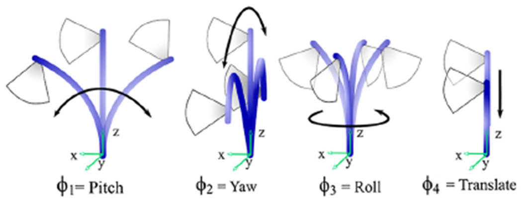
Joint inputs and corresponding tip motions adjust the US imaging plane.
US catheters enable enhanced intra-procedural imaging of working instruments and cardiac structures, such as catheter ablation lesion formation (Cooper and Epstein, 2001; Dravid et al., 2008; Epstein et al., 1998; Marrouche et al., 2003; Ren and Marchlinski, 2007), but manual navigation of US catheters is difficult in terms of the physical and cognitive burden on the clinician. Manual US catheter steering requires significant training. As a result, US catheters are typically only used for the most critical phases of a procedure, such as transseptal puncture (Jongbloed et al., 2003).
Therefore, we apply our motion compensation technology to automatically steer an US catheter imager towards a manually steered ablation catheter tip as a clinician uses the ablation catheter to interact with tissue in an in vivo animal model (Figure 3). This would enable continuous visualization of ablation catheter tissue interactions. In our example procedure the US catheter is introduced through the femoral vein, through the inferior vena cava (IVC), and to the right atrium (RA). The US catheter is manually introduced to the cardiac space, and robotically controlled within the cardiac space. The ablation catheter (manual control) is introduced through the femoral artery, over the aortic arch, and located in the left ventricle (LV). The tip of the US catheter is typically in free space within the chamber (whereas the ablation catheter is typically making contact with tissue). Both catheters are sensed by electromagnetic (EM) tip sensors, which are incorporated into electronanatomical mapping systems (Biosense Webster, Inc., 2018) and used in catheter labs designed to minimize EM disturbances.
Fig. 3.

The robotic system automatically steers an US catheter in the RA to aim the US imager at a target ablation catheter in the LV.
2. Methods
As we work towards applying motion compensation technology to in vivo US catheter imaging there are a few steps we must take. First, we examine potential motion compensation strategies and select which to pursue. Second, we analyze physiological motion data to gain further insight on how breathing affects US catheter motion. Third, we define models that represent tip and base pose motion throughout the breathing cycle. Fourth, we derive predictive algorithms to eliminate time delays. Finally, we combine motion compensation with predictive filtering and determine how these strategies affect kinematics calculations.
2.1. Motion strategy
Breathing motion causes cyclical disturbance to the catheter pose. The magnitude of the disturbance depends on the location of the catheter within the heart, and this affects the tip of the bending section differently from the base of the bending section. In our initial in vivo studies (Degirmenci et al., 2016) the robot was able to reject breathing disturbances and navigate the pose of the US imager accurately with respect to the world coordinate frame. However, as breathing altered the location of the heart tissue with respect to the world coordinate frame (due to cardiac displacement, cardiac orientation changes, and non-rigid deformation), this resulted in poor US imager alignment while the robot was attempting to image the target. The lack of sustained US imager alignment is a problem in two visualization modes.
Mode 1: Imaging tissue for volume reconstruction.
The US catheter pose is steered and localized during image acquisition, but it is not possible to localize a specific region of tissue given the current sensing strategy. Breathing motion causes coordinate frame drift, which results in the US imager pointing at different tissue. The imager must be made to continue pointing in the same direction relative to the disturbance by respiratory motion.
Mode 2: Instrument tracking.
The system is able to sense the location of a target instrument (e.g., ablation catheter) with respect to the US imaging catheter. However, the instrument in another region of the heart is disturbed differently by breathing motion. In addition, the bandwidth limitations of the robot and the catheter cause US alignment delays, leading to discontinuities in visualization.
In both cases, knowledge of respiratory motion and how it relates to robot-actuated motion during catheter navigation is needed. The effect of respiratory motion on the catheter can be measured by the EM sensors on the US catheter, but this only measures respiratory effects while the robot is not actuating the catheter. If the robot is actuating any of the four catheter controls, then the catheter tip pose measurements observe a combination of respiratory motion and robot-actuated motion, and it is not possible to observe either of those motions independently. To enable motion compensation by observing catheter pose separately from anatomical motion, we choose a sensing strategy with the existing clinical environment in mind. We use EM sensors to measure the effects of respiratory motion on the US catheter by deactivating the motors and measuring catheter tip and bending section motion due to breathing disturbance only. Then during active steering, we compare the current pose measurements to model-based breathing estimates. The difference represents the motion due to robot actuation.
2.2. Defining coordinate frames
We accomplish this by measuring the catheter tip (CT , the location of the US transducer), the base of the distal bending section (BB), and the working instrument pose (Instr), across multiple breathing cycles while the robot is not actuating the controls. Coordinate frames are shown in Figure 4. The World frame refers to the EM tracker transmitter and BT refers to the tip of the bending section. One EM sensor is mounted between the CT and BT frames (no bending occurs between CT and BT, so their relationship is constant). A second EM sensor is mounted just proximal to the BB frame. A third EM sensor is mounted to the Instr frame on the catheter being tracked. Green dotted lines demonstrate typical CT, BB, and Instr motion trajectories.
Fig. 4.

Coordinate frame motion due to respiration: CT, catheter tip; BB, base of distal bending section; Instr, working instrument pose; and World, EM tracker transmitter. Green dotted lines demonstrate typical motion trajectories. EM sensors are mounted at BB, BT, and Instr. The cyan rectangle at the CT frame is the US imaging transducer.
Note: Please refer to the online version for colour figure.
Breathing models of CT, BB, and Instr are calculated initially and then used throughout navigation to estimate the amount of motion from respiratory effects versus robot actuation. During instrument tracking it is possible to continuously sense the Instr pose and update the Instr model throughout time. This is because the working instrument is only affected by breathing motion (unless the clinician is manually navigating it). In contrast, once the CT and BB respiratory motion models are calculated it is not possible to update the models from CT and BB measurements as long as the robot is actuating the control knobs. Potential strategies for updating the CT and BB models using indirect measurements during robot motion are beyond the scope of this work.
If the US catheter moves to a new location in which respiratory motion affects the catheter differently, then the CT and BB models will not be updated to reflect this. Small changes in frequency can also eventually result in the model predicting poses that are out of phase with the breathing cycle. Therefore, the system will continuously monitor the frequency with external sensing by a fourth EM sensor on the patient’s chest and update the frequency components of the CT and BB models accordingly. US image-processing feedback for robot control is not examined in this work.
2.3. Measuring respiratory motion
While the US catheter used in these experiments features a built-in EM sensor at the tip, it was not possible to access the tracker data due to proprietary restrictions. Instead, EM sensors from an external tracking system were mounted to the catheters. We studied the effect of respiratory motion on cardiac catheters during in vivo porcine tests by measuring US catheter tip motion with a 6-DOF EM tracking system (trakSTAR, Ascension Technology/NDI, Ontario, Canada) while the catheter was in the RA and the handle was not actuated. The EM tracker system features 0.5 mm and 0.1° resolution, 1.4 mm and 0.5° RMS accuracy, and was sampled at 42 Hz.
The subject was breathing on a respirator. Figure 5 shows the raw data (blue), with both cardiac (2 Hz) and respiratory (0.2 Hz) motions, and the low-pass-filtered data isolating respiratory motion (red). The respiratory motion dominates the cardiac motion in terms of disturbance to the catheter. The low pass filter used a Hamming window of length 51 and cut-off frequency 1 Hz. A sequence of low-pass-filtered breaths was analyzed to calculate breath-to-breath variations (Figure 6). The mean of cycles is shown in black with 95% confidence intervals shaded gray. The maximum standard deviation of 0.11 mm was small enough to neglect amplitude variations, meaning that respiration disturbs the catheter tip repeatedly enough that we can represent the average breath by a model.
Fig. 5.
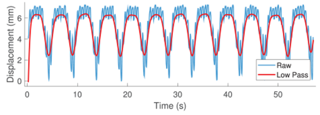
In vivo catheter tip displacement and low-pass-filtered data used for developing the respiratory motion model.
Fig. 6.
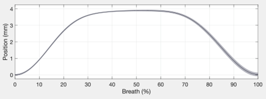
Breath-to-breath variations in catheter tip displacement.
2.4. Modeling respiratory disturbance
We define periodic models for the low-pass-filtered CT, BB, and Instr disturbance motions due to respiration as described and bench top tested in Loschak et al. (2017). All coordinate frame breathing motion trajectories in Figure 4 are cyclical but different from each other. An example model on in vivo breathing data is shown in Figure 7. The blue line represents the raw EM measurements of the CT y- coordinate. The black line represents the low-pass-filtered CT y-coordinate. The red line represents the initialized Fourier series model estimate. The mean absolute error between the y-coordinate model values and the low-pass-filtered measurements is 0.057 mm (σ = 0.041 mm). The mean absolute model error for the x-axis is 0.037 mm (σ = 0.027 mm) and for the z-axis is 0.039 mm (σ = 0.028 mm).
Fig. 7.
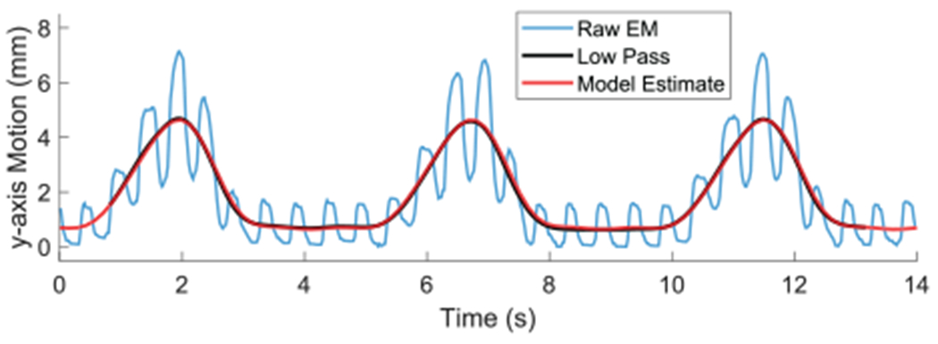
Breathing model of low-pass-filtered CT y-coordinate motion.
The 6-DOF CT pose can be represented by seven parameters: x, y, z, and the rotation matrix converted to an equivalent axis representation (axis x-, y-, z-components, and angle of rotation). The 1D signal initialization process is performed for each of the seven parameters for both CT and BB. The robot will then begin actuating the pull wires and rotating the handle to steer the catheter to compensate for this breathing model.
The first estimated frequency value typically becomes outdated within 30 seconds, causing the predicted breathing pose to become out of phase with the actual breathing cycle and leading to poor steering results. A peak detection algorithm calculates the breathing frequency from the exterior sensor (the fourth EM sensor) and applies it to the original initialization data. As a result, a model can continue providing accurate CT and BB pose estimates for much longer. The in vivo breathing model error after two minutes was typically 0.8 mm.
2.5. Predicting target motion
The system inherently has some delay for sensor measurements, calculations, actuator inertia, and taking up slack in pull wires. This means that a target object may be in a different location by the time the US catheter is able to converge on the previously desired pose. Therefore a multi-step extended Kalman filter (EKF) was designed to continuously estimate the future target position and adjust the US catheter steering ahead of time (Figure 8) (Loschak et al., 2017). The multi-step EKF operates on a Fourier series model of the target’s cyclic motion, which enables better predictions (Yuen et al., 2009). It uses outdated information (due to the low-pass filter and system delays) to estimate the target position into the future to compensate for hardware/software delays.
Fig. 8.

Multi-step EKF uses past reliable information to predict a future time step. New measurements are used to update the Kalman gains for the past.
Each coordinate of the target position (x, y, z) is filtered separately. The state space model for the system (derived in Loschak et al. (2017)) is
where is the predicted state at a given time k, FM is the prediction matrix, μ is the random step of the states, M1 is the number of samples predicted ahead due to hardware and software limitations, and M2 is the number of samples ignored due to the low-pass-filter window size.
2.5.1. Predictive filter simulation.
The EKF was tested on pre-recorded data from earlier in vivo animal trials. The low-pass-filter window size parameter was set to M2 = 35 samples (0.819 s). Predictions were calculated for the future time point at M1 = 20 steps (0.468 s, experimentally determined). The first N data points were used for initializing the breathing model and calculating the first state, covariance matrix, and Kalman gain. Data points were then given to the EKF sequentially to simulate live sensor measurements.
The EKF predicted the state for the future time point. Then the next measurement was given to the EKF and the multi-step EKF cycle repeated until the end of the data set. Figure 9 shows the results of the simulation. The red line represents the low-pass-filtered tip displacement. The blue line, which begins at t ≈ 12 s after initialization, represents each predicted signal point based on only pre-existing information. The mean absolute error between each predicted value and the measured value was 0.088 mm (σ = 0.114 mm). Loschak et al. (2017) presented bench-top target tracking tests with the target attached to a respiratory motion simulator with and without the EKF, which demonstrated the benefits of predictive filtering in cyclical physiological motion compensation.
Fig. 9.
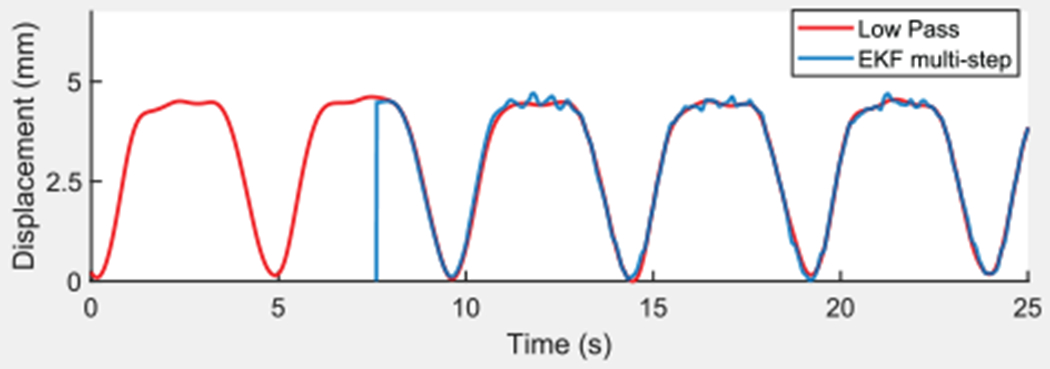
Low-pass-filtered CT displacement and multi-step EKF simulation from pre-recorded data.
The EKF variance and uncertainty parameters described in Loschak et al. (2017) were robust to changes in bench-top tests and little tuning was performed. The most sensitive parameters were M1 and M2. If the predictions were calculated too far into the future, or if the data used to calculate the predictions were too old, then small variations in the breathing model over time reduced navigational accuracy. The same parameters and gains determined in Loschak et al. (2017) on the bench top were used in vivo in this study.
2.6. Coordinate frame calculations
Coordinate frame calculations are used to relate between measured and predicted coordinate frame poses to prepare inputs for the kinematics calculations. In all steering modes the coordinate frame calculations determine the current tip pose with respect to the current base (), the relative desired pose adjustments (Δxyzψ), and the amount of BB roll in the bending section (γcurr).
The following poses are needed:
the fixed BB pose with respect to the EM tracker field generator coordinates, ;
the current CT pose measured with respect to the fixed base, ;
the estimated CT pose due to the breathing motion trajectory model, ;
the current BB pose measured with respect to the fixed base, ;
the estimated BB pose due to the breathing motion trajectory model, .
The pose is a constant transform that can be defined at any point in the breathing cycle. It is defined once each time the US catheter is manually moved or tele-operated to a new location in the heart. The current CT and BB poses are measured continuously. The estimated tip and base poses, CTTraj and BBTraj, are recalculated continuously from the trajectory models at each time point.
The pose is an estimate of the robot-actuated movement. The pose is an estimate of the uncontrollable BB motion due to robot actuation. These estimates can be used in order to find the relative amount of US imager angle adjustment, ψ, as well as the amount of catheter handle roll expressed at the bending section, γcurr.
The relative desired pose adjustment, Δxyzψ, is determined based on the type of motion desired.
Mode 1: Imaging tissue for volume reconstruction.
This mode navigates the US tip to a desired pose. The desired pose adjustment is set equal to the difference between the current CT and the current CTTraj poses plus an additional US imager rotation or displacement command. It is not possible with the given sensing strategy to directly measure the tissue location, but it is possible to maintain the catheter’s pose in the heart chamber with respect to the breathing motion disturbance.
Mode 2: Instrument tracking.
The US imager is rotated to track a moving target while the catheter tip position is commanded to remain constant with respect to the heart chamber (Figure 10). Maintaining US imager alignment requires coordinated motion of all 4 DOFs, and requires extensive training to perform manually.
Fig. 10.
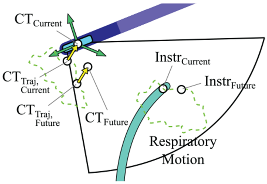
Orienting the imager to tracking an instrument with predictive filtering (mode 2).
The green dotted line represents cyclical CT and Instr pose motion due to respiration only. The current expected CT pose due to breathing only is CTTraj, Current, and the current measured CT pose is CTcurrent. The yellow arrow represents the transform between the expected pose and the actual measured pose, . The current target position is InstrCurrent. The EKF is used to estimate the future target position, InstrFuture. The breathing model is used to calculate CTTraj, Future for the same time point. Here is applied to CTTraj, Future to calculate the expected CT pose at that time point based on the current difference between the measured and expected poses: CTFuture. The orientation angle to adjust, Δψ, is calculated between CTFuture and InstrFuture. The position change is the difference between CT Traj, Current and CTCurrent.
2.7. Controller
The methods described above can be summarized in the instrument tracking controller diagram Figure 11. The gray box includes system measurements and calculations. External disturbances from cardiac and breathing motions affect the US catheter and imaging target. The blue box highlights the catheter breathing model. A set of CT and BB sensor measurements is used to calculate the breathing model. Once the robot begins actuation, the catheter breathing model can no longer be updated from CT and BB measurements. An EM sensor on the subject’s chest continuously measures the breathing period that is used to update the breathing model frequency.
Fig. 11.
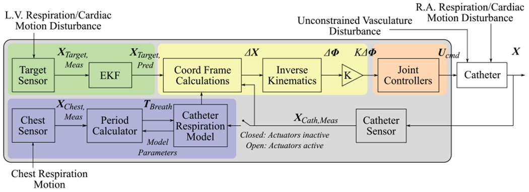
Motion compensation control diagram.
The green box highlights target prediction. Physiological LV motion shifts the target position. The target is sensed and its motion is predicted by the EKF. The coordinate frame calculations block uses the target prediction, catheter breathing model, and catheter sensor information to calculate , γcurr, and Δxyzψ. These values are grouped into the label ΔX.
The kinematics block then calculates the desired joint space adjustments ΔΦ, the robot actuates the catheter handle, and the catheter moves. Unconstrained disturbances from the vasculature affect the robot commands. Physiological motions in the RA disturb the catheter tip pose. The catheter tip sensor measurements are used to create a new set of coordinate frame calculation inputs and the controller iterates.
3. Experiments and results
3.1. Sensing and accuracy
The accuracy requirements of the robot can be calculated by the US catheter tip sensing specifications, the US imaging plane thickness, and the target dimensions (Figure 12). The goal is to maintain the target within the US image plane despite robot errors. The in vivo catheter lab environment was designed for low EM interference. The US plane thickness varies by depth away from the transducer. The US plane thickness was approximately 6 mm at the depth used during experiments. The target in this study was 2 mm in diameter.
Fig. 12.

The accuracy specifications are based on this analysis of US imager thickness and EM sensor errors.
EM tracker errors may result in misalignment between the US plane and the target. In the worst-case EM tracker error (1.4 mm and 0.5°), a target at an imaging depth of 70 mm would still be within the imaging plane, and the robot would have additional allowable errors of 1.5 mm or 1.25°. The US imaging plane thickness is often greater than 6 mm and the relative measurements between EM trackers are often more accurate than the manufacturer’s specification, and therefore the US imager is likely to be visualizing the target even if the measured navigation error is larger than the calculated allowable errors.
3.2. Experimental design
In vivo animal testing was performed on a 64 kg live porcine model due to similarities between human and porcine cardiac anatomy. The in vivo protocol was approved by the Harvard University Institutional Animal Care and Use Committee (IACUC). The animal received humane care in accordance with the 1996 Guide for the Care and Use of Laboratory Animals, recommended by the US National Institutes of Health.
Before the procedure, two EM trackers were mounted to the US catheter at the BT and BB frames. A third EM tracker was mounted to the Instr frame on the target catheter (6 Fr quadpolar catheter). The three sensors were calibrated to the catheters on the bench to calculate a constant transformation matrix before introduction to the animal. Externally mounting and calibrating the EM sensors is only necessary for the translational nature of this experiment lacking access to the catheters’ built-in EM sensor data. The fourth EM tracker was later mounted to the subject’s exterior chest wall while lying supine on the operating table (no calibration needed). The tracker can be mounted in any place that exhibits displacement due to respiration.
The US catheter with two EM sensors was introduced through the 14 Fr introducer in the femoral vein to the RA. The target catheter was introduced through an 11 Fr introducer in the femoral artery to the LV as in Figure 13. The subject’s heart rate was paced at 120 bpm. The ventilator pumped 800 cm3 of air into the subject’s lungs every 7.5 s.
Fig. 13.
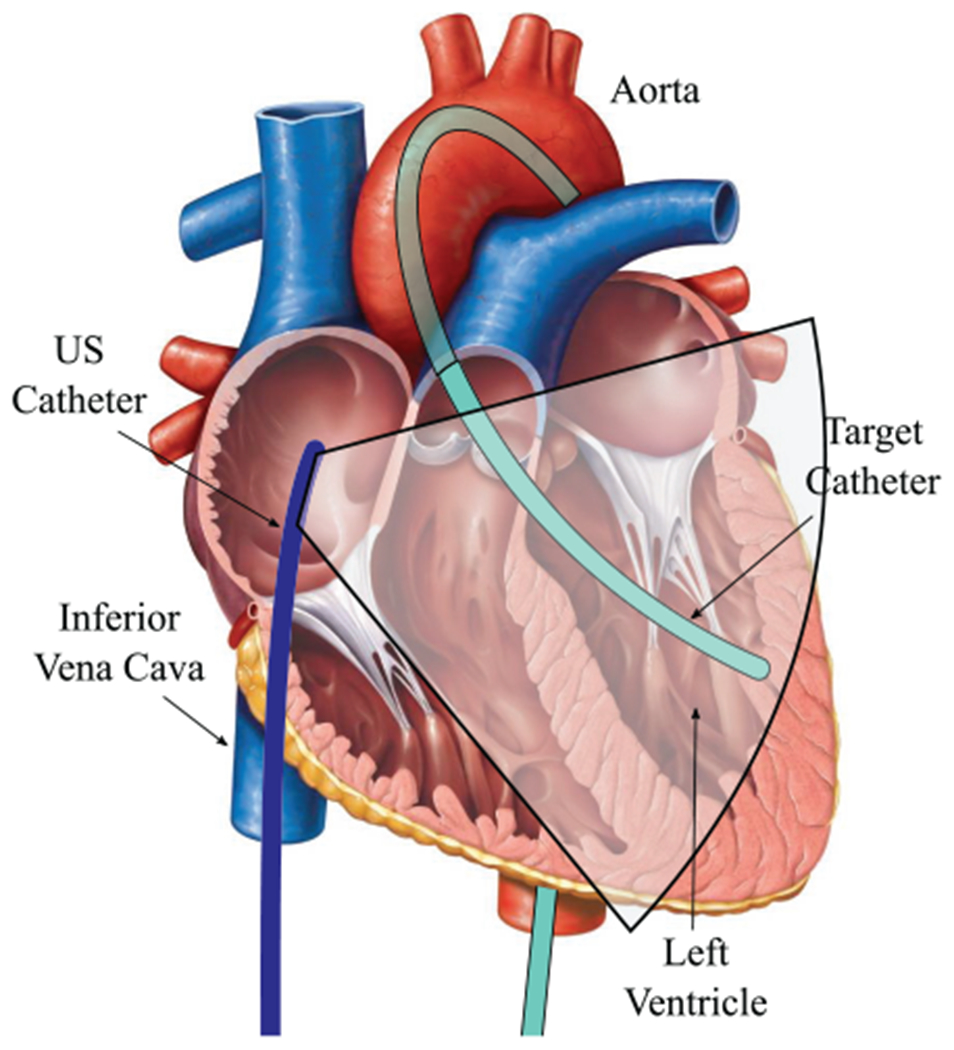
Experimental design schematic with US catheter in RA and target catheter in LV Original cardiac anatomy image from Marieb (2013).
In our previous in vivo studies the introducer seal caused a number of problems with friction and propping open the rubber seal causing blood leakage from the femoral vein. In this study, we used a brass tube (diameter 6 mm, length greater than 2 cm) to completely prop open the seal (Figure 14), greatly reducing the negative effects of friction on steering motion. The brass tube was fit into place by first sliding it over the catheter tip to rest at the proximal handle. After the US catheter was introduced to the RA, the tube was then forced into the seal. This process was borrowed from existing sheath and guidewire catheterization techniques. Silicone grease was packed into the tube around the US catheter body and EM sensor wires to prevent blood leakage. This process was designed specifically for translational non-survival animal procedures in which an EM sensor must be attached to the exterior of the US catheter. If the robot has access to the built-in EM housed within the catheter tip, then this technique would not be necessary.
Fig. 14.

Introducer seal stented open by a brass tube filled with silicone. Inset shows cross-sectional diagram of introducer seal.
3.3. In vivo experiments
3.3.1. Mode 1: Imaging tissue for volume reconstruction.
The US catheter was commanded to stay in the same relative location inside the RA during breathing while pointing at anatomical structures. The breathing model was initialized and then the robot was given relative step input commands of 2° as the US imager was rotated throughout the chamber. Step input rotations were commanded a total of 18 times through a total of 133 seconds. The system navigated the catheter to the desired pose with respect to the moving coordinate frame while compensating for respiratory motion.
Figure 15 shows an example data set containing five step input commands of 2°. Cardiac disturbance to the catheter is observed in the measurements. Figure 15(A) shows desired and measured US catheter tip position as the system compensates for respiratory motion. Only the y-position is shown for ease of visualization. Figure 15(B) shows the overall position error. Figure 15(C) shows the US imager alignment error as the system adjusts the imager to point in the desired direction. The black dots represent moments in which the next step input command was given. The mean absolute error across 134 seconds of accurate motion compensation was 0.98° (σ = 0.79°) and 2.56 mm (σ = 1.67 mm). In other navigation tests the breathing model became outdated or the US catheter shifted to a new position for which the model was no longer representative of the breathing motion. In these instances the system remained stable but with lower accuracy. The mean absolute error across poorly-modeled trials was 2.27° (σ = 2.25°) and 6.59 mm (σ = 4.52 mm).
Fig. 15.

Errors from US imager angle step input commands while compensating for respiratory motion in vivo: (A) desired and measured y-position; (B) position error; (C) pointing angle error. Measurements also show 2 Hz cardiac disturbance. Black circles represent time points when step inputs are commanded.
3.3.2. Mode 2: Instrument tracking.
The goal of this test was to maintain US imager alignment with the target catheter with respiratory motion compensation and the EKF. The target catheter tip was in the LV. At the US catheter tip the breathing motion amplitude was 7.3 mm and the cardiac motion amplitude was 2.8 mm. At the base of the US catheter bending section breathing motion amplitude was 11.7 mm and the cardiac motion amplitude was 0.8 mm. At the tip of the target catheter the breathing motion amplitude was 3.7 mm and the cardiac motion amplitude was 15.3 mm. These values highlight the drastic differences between respiratory and cardiac motion effects in different regions of the heart.
Breathing models were initialized, the EKF was initialized, and then the robot was activated to begin tracking. The system maintained the same position of the catheter tip with respect to the breathing motion and continuously rotated the US imager to align with the predicted target location.
This test was repeated multiple times for an aggregated 329 seconds. Figure 16 shows an example data set. Figure 16(A) shows desired and measured US catheter tip position as the system compensates for respiratory motion and uses the EKF to predict imager target motion. Only the x-position is shown for ease of visualization. Figure 16(B) shows the overall position error, Figure 16(C) shows the error angle between the US imager and the imaging target, and Figure 16(D) shows the x-position of the imaging target throughout the cycle. The target position is shown for context regarding when the target changes direction and when the imager angle error reaches its peak values. Table 1 summarizes instrument tracking results from 329 seconds of active tracking.
Fig. 16.

Pointing the US imager at a target catheter with breathing motion compensation and predictive filtering in vivo: (A) desired and measured x-position; (B) xyz-position error; (C) imager angle error; (D) target x-position for context.
Table 1.
Imaging results from mode 2: Instrument tracking with EKF.
| Metric | Results: Mean (σ) |
|---|---|
| Angle error (°) | 1.33 (0.85) |
| Position error (mm) | 1.05 (0.48) |
| Percentage time within 0.5° | 18.40 |
| Percentage time within 1° | 38.55 |
| Percentage time within 2° | 79.74 |
| Percentage time within 1 mm | 48.87 |
| Percentage time within 2 mm | 96.34 |
3.3.3. Tracking manual target motion.
The goal of this test was to demonstrate breathing motion compensation for automatic US imager alignment with a target that was manually steered, and therefore it was not possible to use the EKF for predictive filtering on the target. Breathing models were initialized and then the robot was activated to hold its position in the RA and align the imaging plane with the target. The target catheter was manually steered throughout the LV by the clinician. The clinician moved the target with varying displacements and velocities. Each time the target was moved out of view, the robot automatically reoriented the US imager to find the target tip. A labeled US video demonstration is available in the supplementary materials.
This test was repeated multiple times for a combined total 431 seconds of tracking. Figure 17 shows an example data set. The upper data plot in Figure 17 shows the target displacement and the lower data plot shows the error angle between the US imager and the target. At t = 0 s the US catheter was pointing at the target (Figure 17(A)). Near t = 12 s the clinician moved the target catheter by roughly 15 mm, causing the tip to go out of view (Figure 17(B)). By t = 14 s the system successfully reoriented the US imager to bring the target catheter back into view (Figure 17(C)). In 431 seconds of tracking, including the moments when the clinician moved the target out of view, the mean absolute angle error was 2.81° (σ = 2.60°). Higher US imager alignment errors correspond with large respiratory movements because the target catheter was positioned in a region of the LV in which it was more affected from respiration than in other tests, and using the EKF is not useful for tracking a manually steered target catheter. The US catheter maintained its position with mean absolute error 2.14 mm (σ = 1.48 mm). The catheter tip was within 1 mm of its desired position 16.65% of the time and within 2 mm for 57.33% of the time.
Fig. 17.
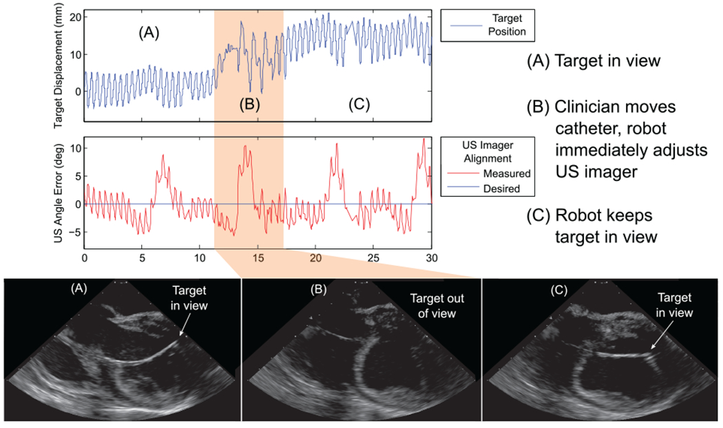
Results of tracking manual target motion, automatically pointing the US imager at a manually steered target catheter in vivo: (A) robot points US imager at target; (B) clinician moves target out of view; (C) robot reorients US imager to continue pointing at target.
4. Discussion
In this work, we have demonstrated automatic cardiac catheter navigation in vivo with single millimeter- and degree-level pose errors despite disturbances. These results are the most accurate in vivo robotic cardiac catheter navigation known to the authors (compared with reported 6.53 mm mean accuracy in Ganji and Janabi-Sharifi (2009)). This required engineering solutions to the three key challenges: nonlinear effects such as friction and slack in the catheter, rejecting unmodeled uncontrollable disturbances to the catheter body, and compensating for cyclical physiological disturbances to the US catheter tip through predictive filtering of imaging target motion. This was validated through in vivo animal studies by automatically steering an US catheter in the RA to visualize a target ablation catheter in the LV.
The control strategy relied on decoupling respiratory motion from motion due to catheter actuation for robotic steering. This enabled the system to calculate adjustments to the US catheter and maintain US imager alignment with the target. While the respiration model is necessary for decoupling robot motion from patient motion, a downside to this strategy is that most model parameters can only be trained and updated when the catheter is not being actuated. Moving the US catheter to a new region of the heart reduces model accuracy, and robot actuation must be paused temporarily while a new model is trained. This is the result of respiratory motion affecting each region of the heart differently. In addition, it is not possible to directly measure the location of the cardiac tissue unless image processing techniques are used to localize the tissue in view. Even then, out-of-plane motion is challenging to measure with a 2D US probe.
Other methods for decoupling actuation from respiratory motion may avoid these limitations. Full and continuous respiratory motion tracking from external imaging sources (CT, MR, or 3D US) would be necessary in the long term for compensation of arbitrary tissue interaction. Catheter redesign may include full catheter shaft shape sensing (fiber Bragg grating) as well. This would require additional cost, radiation, and/or large equipment in the catheter lab. By comparison, our proposed sensing strategy uses widely available commercial US imaging catheters and mapping systems with EM tracker technology, which are already configured for use in electrophysiology procedures.
Overall, the results demonstrate that the proposed methods enable a robotic US catheter to (A) maintain pose and to (B) point the US imaging plane with the accuracy required for procedure guidance during catheter-based cardiac interventions. Two different motion compensation problems were addressed. First, maintaining the robotic US catheter pose took advantage of the repeatability of mechanical ventilation to derive a quasi-static model that achieved 1–2 mm and 1–2° RMS pose accuracy for several minutes. Second, an EKF-based estimator was implemented to enhance tracking of target motion (which differed from the robotic catheter motion pattern). Together, these methods enabled accurate navigation through respiratory motion which was not able to be examined in our previous in vivo studies before this motion compensation strategy was developed (Degirmenci et al., 2016).
Throughout the in vivo procedure the patient was sedated and breathing consistently on a ventilator. Without a ventilator, a potentially variable volume of air in the lungs could disturb cardiac tissues differently on subsequent breaths, which would significantly reduce the modeling accuracy. We use this approach because while not all catherization involves patient sedation, it is standard for a sedated patient to be on a ventilator.
Our in vivo and bench-top results suggest that control performance limits may be set by the mechanics of the US catheter. US catheters are long thin polymer structures 3 mm in diameter, with softer material in the distal 5 cm section where most bending occurs. The actuation system (control handle), consisting of two knobs and four pull wires, suffers from friction, backlash, and elongation, and the mechanical behavior of the actuation changes beginning after only a few dozen cycles.
Catheter mechanics also limit motion compensation bandwidth. Cardiac motion disturbances (2 Hz) are beyond the intended robot bandwidth, as the commercial US catheter is designed for manual operation and the required high speeds and large number of cycles would exceed the catheter’s mechanical design. The motion compensation methods in this work are not limited to respiratory motion, but are applicable to compensating for any repeatable cyclical motion, which may be subject to change over time. This includes cardiac motion with a higher-bandwidth catheter. These methods can also be applied to any flexible pull wire actuated manipulators, such as endoscopes.
While it would be possible to greatly improve the mechanics of these catheters, any redesign would obviate the benefits of working with a commercially available, widely used device that has regulatory clearance in many countries. Fortunately, this does not limit the clinical utility of the robotic system. The results presented here show that adequate performance in vivo can be obtained with appropriate control methods because target tissue and instruments remain within the US imaging plane despite disturbances.
5. Conclusion
This paper has presented the first system to automatically steer cardiac catheters with physiological motion compensation and predictive filtering target tracking in vivo. By robotically actuating an off-the-shelf US catheter, we have demonstrated that it is possible to automatically orient the US imager towards desired anatomical structures or working catheters despite large respiratory motions. This has been achieved by modeling quasi-periodic physiological motions and compensating for them using a kinematics-based model of the US catheter. These results have the potential to improve the diagnosis and interventional treatment of cardiac diseases. The navigation strategies described above were demonstrated with cardiac catheters, but they are also applicable to other flexible systems for medical or non-medical purposes. Application of this work may improve minimally invasive surgery with flexible manipulators.
Supplementary Material
Acknowledgements
The authors would like to acknowledge Laura J Brattain, PhD, for her work developing the automated US catheter steering system for early bench-top studies and in vivo trials. The authors would like to acknowledge Yaroslav Tenzer, PhD, for mechanical design and James Weaver, PhD, for manufacturing assistance and informative discussions.
Funding
The author(s) disclosed receipt of the following financial support for the research, authorship, and/or publication of this article: This work was supported by the American Heart Association (grant number 15PRE22710043), National Institutes of Health (grant number 1R21EB018938), and Harvard Paulson School of Engineering and Applied Sciences.
References
- Biosense Webster, Inc; (2018) CARTO System. Available at: http://www.biosensewebster.com/products/carto-3.aspx (accessed 19 September 2018). [Google Scholar]
- Camarillo DB, Carlson CR and Salisbury JK (2009) Configuration tracking for continuum manipulators with coupled tendon drive. IEEE Transactions on Robotics 25(4): 798–808. [Google Scholar]
- Catheter Robotics, Inc. (2018) Amigo Remote Catheter System. Available at: http://www.catheterprecision.com/rcs-main.htm (accessed 19 September 2018). [Google Scholar]
- Cooper JM and Epstein LM (2001) Use of intracardiac echocardiography to guide ablation of atrial fibrillation. Circulation 104(25): 3010–3013. [DOI] [PubMed] [Google Scholar]
- Corindus, Inc; (2018) CorPath Robotic PCI. Available at: www.corindus.com/corpath-grx/how-it-works/ (accessed 19 September 2018). [Google Scholar]
- Cuvillon L, Gangloff J, de Mathelin M and Forgione A (2005) Toward robotized beating heart TECABG: Assessment of the heart dynamics using high-speed vision. In: International Conference on Medical Image Computing and Computer-Assisted Intervention Berlin: Springer, pp. 551–558. [DOI] [PubMed] [Google Scholar]
- Degirmenci A, Loschak PM, Tschabrunn CM, Anter E and Howe RD (2016) Compensation for unconstrained catheter shaft motion in cardiac catheters. In: 2016 IEEE International Conference on Robotics and Automation (ICRA) pp. 4436–4442 [DOI] [PMC free article] [PubMed] [Google Scholar]
- Dravid SG, Hope B and McKinnie JJ (2008) Intracardiac echocardiography in electrophysiology: a review of current applications in practice. Echocardiography 25(10): 1172–1175. [DOI] [PubMed] [Google Scholar]
- Epstein LM, Mitchell MA, Smith TW and Haines DE (1998) Comparative study of fluoroscopy and intracardiac echocardiographic guidance for the creation of linear atrial lesions. Circulation 98(17): 1796–1801. [DOI] [PubMed] [Google Scholar]
- Ganji Y and Janabi-Sharifi F (2009) Catheter kinematics for intracardiac navigation. IEEE Transactions on Biomedical Engineering 56(3): 621–632. [DOI] [PubMed] [Google Scholar]
- Hansen Medical, Inc; (2018) Sensei X Robotic Catheter System. Available at: http://www.hansenmedical.com (accessed 19 September 2018). [Google Scholar]
- Jongbloed MRM, Bax JJ, de Groot NMS, et al. (2003) Radiofrequency catheter ablation of paroxysmal atrial fibrillation; guidance by intracardiac echocardiography and integration with other imaging techniques. European Heart Journal - Cardiovascular Imaging 4(1): 54–58. [DOI] [PubMed] [Google Scholar]
- Kesner SB and Howe RD (2014) Robotic catheter cardiac ablation combining ultrasound guidance and force control. The International Journal of Robotics Research 33(4): 631–644. [Google Scholar]
- Khoshnam M, Azizian M and Patel RV (2012) Modeling of a steerable catheter based on beam theory. In: 2012 IEEE International Conference on Robotics and Automation (ICRA), pp. 4681–4686. [Google Scholar]
- Loschak PM, Brattain LJ and Howe RD (2017) Algorithms for automatically pointing ultrasound imaging catheters. IEEE Transactions on Robotics 33(1): 81–91. [DOI] [PMC free article] [PubMed] [Google Scholar]
- Loschak PM, Degirmenci A and Howe RD (2017) Predictive filtering in motion compensation with steerable cardiac catheters. In: 2017 IEEE International Conference on Robotics and Automation (ICRA), pp. 4830–4836. [DOI] [PMC free article] [PubMed] [Google Scholar]
- Marieb EN (2013) Human Anatomy & Physiology. 9th Ed New York: Pearson. [Google Scholar]
- Marrouche NF, Martin DO, Wazni O, et al. (2003) Phased-array intracardiac echocardiography monitoring during pulmonary vein isolation in patients with atrial fibrillation impact on outcome and complications. Circulation 107(21): 2710–2716. [DOI] [PubMed] [Google Scholar]
- Moscucci M (2013) Grossman & Baim’s Cardiac Catheterization, Angiography, and Intervention. Philadelphia, PA: Lippincott Williams & Wilkins. [Google Scholar]
- Ott L, Nageotte F, Zanne P and De Mathelin M (2011) Robotic assistance to flexible endoscopy by physiological-motion tracking. IEEE Transactions on Robotics 27(2): 346–359. [Google Scholar]
- Parker PJ and Anderson BDO (1990) Frequency tracking of non-sinusoidal periodic signals in noise. Signal Processing 20(2): 127–152. [Google Scholar]
- Penning RS, Jung J, Borgstadt JA, Ferrier NJ and Zinn MR (2011) Towards closed loop control of a continuum robotic manipulator for medical applications. In: 2011 IEEE International Conference on Robotics and Automation (ICRA), pp. 4822–4827. [Google Scholar]
- Ren J- F and Marchlinski FE (2007) Utility of intracardiac echocardiography in left heart ablation for tachyarrhythmias. Echocardiography 24(5): 533–540. [DOI] [PubMed] [Google Scholar]
- Riviere CN, Rader RS and Thakor NV (1998) Adaptive cancelling of physiological tremor for improved precision in microsurgery. IEEE Transactions on Biomedical Engineering 45(7): 839–846. [DOI] [PubMed] [Google Scholar]
- Riviere CN, Thakral A, Iordachita II, Mitroi G and Stoianovici D (2001) Predicting respiratory motion for active canceling during percutaneous needle insertion. In: Proceedings of the 23rd Annual International Conference of the IEEE Engineering in Medicine and Biology Society, pp. 3477–3480. [Google Scholar]
- Ryu SC and Dupont PE (2014) FBG-based shape sensing tubes for continuum robots. In: 2014 IEEE International Conference on Robotics and Automation (ICRA), pp. 3531–3537. [Google Scholar]
- Stereotaxis Inc. (2018a) Niobe ES. Available at: http://www.stereotaxis.com/products/niobe/ (accessed 19 September 2018). [Google Scholar]
- Stereotaxis Inc. (2018b) V-Drive Robotic Navigation System. Available at:http://www.stereotaxis.com/products/vdrive/ (accessed 19 September 2018). [Google Scholar]
- Thakral A, Wallace J, Tomlin D, Seth N and Thakor NV (2001) Surgical motion adaptive robotic technology (SMART): Taking the motion out of physiological motion. In: International Conference on Medical Image Computing and Computer-Assisted Intervention Berlin: Springer, pp. 317–325. [Google Scholar]
- Vrooijink GJ, Ellenbroek T, Breedveld P, Grandjean JG and Misra S (2014) A preliminary study on using a Robotically-Actuated Delivery Sheath (RADS) for transapical aortic valve implantation. In: 2014 IEEE International Conference on Robotics and Automation (ICRA), pp. 4380–4386. [Google Scholar]
- Webster RJ and Jones BA (2010) Design and kinematic modeling of constant curvature continuum robots: A review. The International Journal of Robotics Research 29(13): 1661–1683. [Google Scholar]
- Yip MC and Camarillo DB (2016) Model-less hybrid position/ force control: A minimalist approach for continuum manipulators in unknown, constrained environments. IEEE Robotics and Automation Letters 1(2): 844–851. [Google Scholar]
- Yip MC, Sganga J and Camarillo DB (2017) Autonomous control of continuum robot manipulators for complex cardiac ablation tasks. Journal of Medical Robotics Research 2(1): 1750002. [Google Scholar]
- Yuen SG, Kettler DT, Novotny PM, Plowes RD and Howe RD (2009) Robotic motion compensation for beating heart intracardiac surgery. The International Journal of Robotics Research 28(10): 1355–1372. [DOI] [PMC free article] [PubMed] [Google Scholar]
Associated Data
This section collects any data citations, data availability statements, or supplementary materials included in this article.


