

Abstract
The recirculation of gases in a sealed reactor system is a broadly useful method in catalytic and electrocatalytic studies. It is especially relevant when a reactant gas reacts slowly with respect to residence time in a catalytic reaction zone and when mass transport control through the reaction zone is necessary. This need is well illustrated in the field of electrocatalytic N2 reduction, where the need for recirculation of 15N2 has recently become more apparent. Herein, we describe the design, fabrication, use, and specifications of a lubricant-free, readily constructed recirculating pump fabricated entirely from glass and inert polymer (poly(ether ether ketone) (PEEK), poly(tetrafluoroethylene) (PTFE)) components. Using these glass and polymer components ensures chemical compatibility between the piston pump and a wide range of chemical environments, including strongly acidic and organic electrolytes often employed in studies of electrocatalytic N2 reduction. The lubricant-free nature of the pump and the presence of components made exclusively of glass and PEEK/PTFE mitigate contamination concerns associated with recirculating gases saturated with corrosive or reactive vapors for extended periods. The gas recirculating glass pump achieved a flow rate of >500 mL min–1 N2 against atmospheric pressure at 15 W peak power input and >100 mL min–1 N2 against a differential pressure of +6 in. H2O (∼15 mbar) at 10 W peak power input.
Introduction
Piston-based gas recirculator pumps constructed entirely of glass have long been recognized as useful tools when the careful recirculation of a gaseous reactant through a reaction zone is required.1−8 Gas recirculation in a sealed reactor system is a valuable technique in a range of studies, including when reaction rates are slow with respect to the residence time of a reactant gas in the presence of a catalyst and when mass transport control through a reactor is needed. The lubricant-free, leak-free, and chemically resistant nature of these aptly named “glass pumps” is additionally advantageous in precise chemical studies involving gas recirculation in which mitigating contamination and avoiding gas leakage is critical. They also enable reliable gas recirculation through corrosive or reactive media that may otherwise be expected to damage metal and incompatible polymer components.
While glass pumps are useful in a wide range of chemical studies involving gas recirculation, the value of such a recirculator device has recently been evaluated in the study of the electrocatalytic N2 reduction reaction (N2RR). Reports in this field have demonstrated the value of using isotope-labeled 15N2 gas to discriminate between the electrochemically produced NH3 observed as 15NH3 and contaminant NH3 observed as 14NH3.9−11 However, the apparently slow 15N2 to 15NH3 reaction rate, the high cost of 15N2 (∼$500 L–1), and the commonly required combination of a high N2 flow rate (>20 mL min–1) with extended electrolysis times (8+ h) have often made the execution of 15N2-based experiments prohibitively expensive without 15N2 recapture and reuse strategies. Additionally, electrolyte engineering has been suggested as a promising strategy to facilitate efficient N2 reduction, with recent studies executed in a variety of electrolytes, including aqueous acidic and basic as well as nonaqueous electrolytes.12−16 Thus, the ability to recirculate 15N2 through a wide range of electrolyte media without leakage, contamination, or concerns about compatibility between the recirculator and electrolyte is crucial in enabling reliable reports of electrocatalytic N2 reduction.
A glass piston pump satisfies the above requirements associated with N2RR studies. However, despite extensive efforts, we were unable to commercially obtain such a glass pump, and we found that previously reported designs could be improved in terms of both ease-of-construction and operation. In this manuscript, we report our effort to design and operate a modern glass piston pump that can be readily constructed and can enable precise, replicable N2RR studies involving the recirculation of 15N2 gas.
Design and Operation
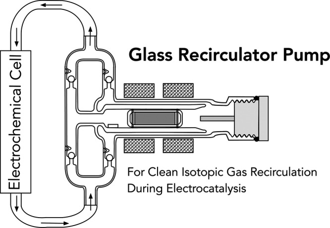
Figure 1 shows a schematic drawing and photograph of the glass pump design (see the Supporting Information (SI) for a detailed schematic). Basic pump operation occurs by alternating the voltage polarity in each of the two magnet coils such that one coil pulls the piston, which contains a magnetic core, toward itself as the other coil simultaneously pushes the piston in the same direction. This induces an oscillating motion in the magnetic piston, compressing gas in the direction of motion. The four check valves are located such that any motion of the piston pressurizes gas at the outlet with respect to the inlet. An electronic microcontroller driving a dual H-bridge and a standard 60 V, 1.5 A power supply control the frequency and strength of the applied potential, which can be manipulated to give a wide range of performance behavior. Table 1 shows a brief overview of flow rates obtained at various power inputs and differential pressures.
Figure 1.

(left) Cross-sectional schematic. Glass materials are in gray, PEEK materials are in yellow, PTFE materials are in blue, and the copper magnet coils are crosshatched. (A) Copper magnet coils; (B) PEEK piston with a NdFeB magnetic core located within a piston tube; (C) ground glass spherical check valves [×4]; (D) PTFE Ace Thred #25 plug with attached tube stopper; (E) antiwedge stop. (right) Picture of the magnetically actuated glass piston pump. See the SI for a detailed schematic including dimensions.
Table 1. Glass Pump Operating Characteristicsa.
| peak power input (W)b | differential pressure (in. H2O)c | flow rate (mL min–1) |
|---|---|---|
| 2.5 | 0.1 | 30 |
| 10 | 0.1 | >500 |
| 10 | 6 | 100 |
| 10 | 10 | 0 |
| 15 | 12 | 0 |
The power input and differential pressure between the outlet and inlet were independently controlled variables, and resultant flow rate was measured. The power input was fixed using the power supply. The outlet pressure was set by attaching a flexible tube to the outlet and submerging it to a fixed depth of water. The flow rate was measured using a standard flowmeter (see the SI for measurement details).
Power input is reported as a peak power input based on power supply readings. Average power input is lower due to the variably intermittent nature of the pump operation (see the SI for details).
Differential pressure is defined herein as the pump outlet pressure with respect to the pump inlet pressure in units of inches of H2O.
To promote ease-of-construction and efficient operation, a number of design choices were made that are distinct from previously reported glass pump architectures. The piston was machined from poly(ether ether ketone) (PEEK) material, which is chemically inert across a wide range of materials. A PEEK piston offers reduced mechanical wear compared to a glass piston. It also exhibits a lower thermal expansion coefficient with respect to poly(tetrafluoroethylene) (PTFE); this allowed for careful sizing of the piston rings to minimize gas blow-by during piston movement while minimizing the likelihood that thermal expansion during operation causes the pump to seize. The magnetic core of the piston enables the synergistic push–pull behavior of the magnet coils with respect to the piston, which is not possible with a standard iron core. Consequently, this enables the tube-in-tube architecture in which the piston tube sits concentrically within a wider diameter gas-transfer tube by allowing the radial distance between the magnet coils and piston to increase without requiring a prohibitive increase in required power input. The tube-in-tube architecture facilitates the placement of the check valves with respect to the piston tube; that is, it allows the piston tube to remain uncaptured on one side. This permits simple mounting and demounting of the magnet coils on the pump arm instead of requiring permanent magnet coil installation prior to glass body construction and allows for easy removal of the piston when maintenance is required. During operation, the pump was held in place using three standard three-prong laboratory clamps although a wide variety of stabilizing strategies should be effective (see the SI). Microcontroller-based operation enables software control of performance characteristics, including rate and variability of gas flow as well as output pressure without requiring hardware manipulation.
Closed-loop recirculation of gases through a sealed reactor has been used for many years in the field of thermal heterogeneous catalysis and more recently in electrocatalysis.7−9,17 Executing these closed-loop experiments introduces a number of considerations that are distinct from electrocatalysis studies that often employ gas flow-through methods. Recycling gases through a sealed reactor inevitably leads to a changing gas composition and pressure (e.g., due to gaseous product formation, electrolyte vaporization, etc.), and these changes must be considered in the context of both reactor safety and the reaction under study. Pressure must always be monitored when using these reactors. In the study of electrocatalytic N2 reduction, one key concern is the evolution of H2 at the cathode, which will pressurize the reactor and also, depending on the electrochemical cell architecture, reoxidize at the anode (see the SI). This introduces both safety (pressurization) and electrochemical/kinetic (depolarization of the anode, H2-enabled chemical and electrochemical side reactions) considerations that should be addressed prior to executing an experiment. The partial pressure of the reactant gas should also decrease as the reaction proceeds, adding complexity to the measured kinetics of the reaction. This may be an important consideration in N2RR studies as new electrocatalysts with high activity are discovered and would be a particularly important factor when studying CO2 reduction under closed-loop recirculation conditions. The significant rates of electrochemical CO2 reduction that have been measured would not only reduce the partial pressure of CO2 in a sealed reactor over time but also introduce volatilized products into the gas stream that could further react and ultimately result in new product distributions.18,19 Sealed reactors also introduce distinct experimental factors with respect to reactor impurities and cell leakage. Unlike gas flow-through reactors in which a constant stream of reactant gas is passed through the electrolyte and therefore constantly introduces small amounts of any undesired impurity that may be present in the gas source, a sealed reactor should only contain a fixed amount of a given reactant, impurity or otherwise, prior to considering any products added to the gas headspace during the chemical reaction. Removing air content prior to experiment can be accomplished by cycling between purging with inert gas and evacuating the reactor. Outgassing and permeation of gases through polymer seals should be considered in the context of the required reaction conditions (see the SI). When pristine air-free conditions are required, the glass pump can further be operated under an inert glovebox atmosphere. We also operate our closed-loop reactors under a slight overpressure (∼+75 mbar) to mitigate the effects of leakage into the system.
We have developed the glass pump described herein to be well suited to recirculation of reactant gases during electrochemical studies with broader applications possible. The pump is able to achieve pressures >6 in. H2O, as well as a ready flow of gas through coarse fritted glass to achieve well-dispersed gas influx into a liquid electrolyte. This clearly demonstrates the utility of the glass pump under the experimental conditions commonly found in electrochemical studies. The pump has performed reliably for over 72 h of continuous operation (2.5 W power input) in a fume hood without an observed rise in temperature of the pump body or the magnet coils, and it has also demonstrated sufficient leak tightness over 44 h (leak rate ∼ 5 × 10⁻⁶ mbar L s–1) with minimal loss of reactant gas as determined by a pressure drop test at slight overpressure (∼+30 in. H2O) in the reactor loop (see the SI for details).20 The pump is amenable to both vacuum and overpressure conditions as limited by the durability of the glass body. Other strategies can also be used to effect gas recirculation, and given the appropriate gas check valve architecture to enforce unidirectional gas flow, a wide range of strategies should be able to circulate gases in a closed loop. Among commercially available pumping strategies that we evaluated were metal-bellows-based pumps as well as diaphragm pumps, and under many experimental conditions, these pumps are highly effective. However, we have found the combination of chemical/mechanical stability to various electrolytes/electrolyte-saturated gases, minimized contamination sources, and robustness to high and low pressure demonstrated by the glass pump to be very valuable in a range of applications, including electrochemical testing. Further, we have found that the ability to see into the pump body, to clean, and to make easy modifications (e.g., replace seals, change pump connectors, etc.) have made the glass pump advantageous in exploratory experimental work where conditions may change quickly or require a multitude of distinct constraints (see the SI for further discussion). The performance of this pump is versatile and can be considered a prototype to be elaborated upon or modified in myriad ways to meet specific experimental needs, including increasing the piston diameter, increasing the piston throw length, improving check/ball valve mating, adding physical stops to supplement software-enforced piston braking, and replacing the polymer components with glass or metallic components (see the SI). The pump performance can also be readily tuned via software control of the magnet coils to achieve the desired stable flow. The maximum pressure attainable can be increased by increasing the power input, and care should always be taken to monitor component pressures and temperatures when operating under new conditions.
Conclusions
Recirculation of reactant gases is a useful experimental method when the reaction rate of a gas is slow compared to the gas flow rate through a reaction zone, when the reactant gas is expensive, and when well-defined control of mass transport through the sealed reactor is needed. A glass piston recirculator pump is a valuable tool to effect gas recirculation, especially when the experimental conditions require minimization of contamination and chemical stability of the recirculator in the presence of aggressive reaction media. Herein, we have described the design and performance specifications of a modern, electronically controlled glass piston gas recirculator pump. The pump performance demonstrated versatility and tunability, and the pump was shown to achieve flow rates in excess of 500 mL min–1 and develop pressures up to 12 in. H2O. The effectively leak-tight, noncontaminating, chemically stable nature of the glass pump enabled effective gas recirculation under a multitude of experimental conditions, making it a valuable tool in a wide range of catalytic and electrocatalytic studies, including those required in isotope-labeled electrocatalytic N2 reduction studies.
Materials and Methods
The glass body of the pump was fabricated by Adams & Chittenden Scientific Glass (Berkeley, CA). The magnetic PEEK piston was fabricated by inserting a PEEK-encapsulated, NdFeB magnet (V&P Scientific, San Diego, CA) into a custom-machined, sealable PEEK piston body. The magnet coils were manually wound using 20 AWG copper magnet wire (TEMCo Industrial, Fremont, CA), and their shape was set using cyanoacrylate adhesive. The glass pump operation was controlled using a microcontroller (Arduino Uno) coupled to an L298-controlled H-bridge motor controller and a variable 60 V, 1.5 A power supply (Protek 3060B). A complete table of the glass pump component parts, including vendor and part numbers, and details of construction can be found in the Supporting Information.
Acknowledgments
This work was supported by a research grant (9455) from Villum Fonden. We thank Dr. Robert Moffatt for assisting with coil design. We thank Dr. Aaron Sattler for helpful discussions on gas recirculation strategies.
Supporting Information Available
The Supporting Information is available free of charge at https://pubs.acs.org/doi/10.1021/acsomega.0c00742.
Detailed characterization of the construction and operation of the piston pump. Example code and wiring for operating a microcontroller. Solidworks design files for piston. Images and movies of pump operation. Extended discussion of gas headspace considerations during electrochemically sealed reactor experiments.21−41 (PDF)
(ZIP)
Author Present Address
⊥ Center for Energy Materials Research, Korea Institute of Science and Technology (KIST), 5, Hwarang-ro 14-gil, Seongbuk-gu, Seoul, South Korea (02792).
The authors declare no competing financial interest.
Supplementary Material
References
- Brunfeldt R. J.; Holm V. C. F. A Magnetically-Actuated Glass Pump for Circulating Gases. J. Chem. Educ. 1955, 32, 528 10.1021/ed032p528. [DOI] [Google Scholar]
- Duncan S.; Lawson F. A Double-Acting All-Glass Gas Circulating Pump. J. Sci. Instrum. 1967, 44, 388. 10.1088/0950-7671/44/5/416. [DOI] [Google Scholar]
- Ellis T. A Demountable Glass Circulating Pump. J. Sci. Instrum. 1962, 39, 234–235. 10.1088/0950-7671/39/5/422. [DOI] [Google Scholar]
- Porter F.; Bard Well D. C.; Lind S. C. An All-Glass Circulating Pump for Gases. Ind. Eng. Chem. 1926, 18, 1086–1087. 10.1021/ie50202a030. [DOI] [Google Scholar]
- Funnell W. S.; Hoover G. I. An All-Glass Gas-Circulating Apparatus. J. Phys. Chem. A 1927, 31, 1099–1100. 10.1021/j150277a009. [DOI] [Google Scholar]
- Chambers R.; Dougharty N.; Boudart M. A Reliable Noncontaminating Gas Recirculation Pump. J. Catal. 1965, 4, 625–626. 10.1016/0021-9517(65)90169-7. [DOI] [Google Scholar]
- Happel J.Introduction. In Isotopic Assessment of Heterogeneous Catalysis; Academic Press: Orlando, FL, 1986; p 14. [Google Scholar]
- Anderson R.Kinetics of Catalytic Reactions. In Experimental Methods in Catalytic Research; Academic Press: New York, NY, 1968; p28. [Google Scholar]
- Andersen S. Z.; Čolić V.; Yang S.; Schwalbe J. A.; Nielander A. C.; McEnaney J. M.; Enemark-Rasmussen K.; Baker J. G.; Singh A. R.; Rohr B. A.; et al. A Rigorous Electrochemical Ammonia Synthesis Protocol with Quantitative Isotope Measurements. Nature 2019, 570, 504–508. 10.1038/s41586-019-1260-x. [DOI] [PubMed] [Google Scholar]
- Greenlee L. F.; Renner J. N.; Foster S. L. The Use of Controls for Consistent and Accurate Measurements of Electrocatalytic Ammonia Synthesis from Dinitrogen. ACS Catal. 2018, 8, 7820–7827. 10.1021/acscatal.8b02120. [DOI] [Google Scholar]
- Chen J. G.; Crooks R. M.; Seefeldt L. C.; Bren K. L.; Bullock R. M.; Darensbourg M. Y.; Holland P. L.; Hoffman B.; Janik M. J.; Jones A. K.; et al. Beyond Fossil Fuel–Driven Nitrogen Transformations. Science 2018, 360, eaar6611 10.1126/science.aar6611. [DOI] [PMC free article] [PubMed] [Google Scholar]
- Singh A. R.; Rohr B. A.; Statt M. J.; Schwalbe J. A.; Cargnello M.; Nørskov J. K. Strategies toward Selective Electrochemical Ammonia Synthesis. ACS Catal. 2019, 9, 8316–8324. 10.1021/acscatal.9b02245. [DOI] [Google Scholar]
- Lazouski N.; Schiffer Z. J.; Williams K.; Manthiram K. Understanding Continuous Lithium-Mediated Electrochemical Nitrogen Reduction. Joule 2019, 3, 1127–1139. 10.1016/j.joule.2019.02.003. [DOI] [Google Scholar]
- Yang X.; Kattel S.; Nash J.; Chang X.; Lee J.; Yan Y.; Chen J.; Xu B. Quantification of Active Sites and Elucidation of Reaction Mechanism of Electrochemical Nitrogen Reduction Reaction on Vanadium Nitride. Angew. Chem., Int. Ed. 2019, 58, 13768–13772. 10.1002/anie.201906449. [DOI] [PubMed] [Google Scholar]
- Yao Y.; Zhu S.; Wang H.; Li H.; Shao M. A Spectroscopic Study on the Nitrogen Electrochemical Reduction Reaction on Gold and Platinum Surfaces. J. Am. Chem. Soc. 2018, 140, 1496–1501. 10.1021/jacs.7b12101. [DOI] [PubMed] [Google Scholar]
- Chen G.-F.; Ren S.; Zhang L.; Cheng H.; Luo Y.; Zhu K.; Ding L.-X.; Wang H. Advances in Electrocatalytic N 2 Reduction-Strategies to Tackle the Selectivity Challenge. Small Methods 2018, 3, 1800337 10.1002/smtd.201800337. [DOI] [Google Scholar]
- Bui L.; Chakrabarti R.; Bhan A. Mechanistic Origins of Unselective Oxidation Products in the Conversion of Propylene to Acrolein on Bi2Mo3O12. ACS Catal. 2016, 6, 6567–6580. 10.1021/acscatal.6b01830. [DOI] [Google Scholar]
- Nitopi S.; Bertheussen E.; Scott S. B.; Liu X.; Engstfeld A. K.; Horch S.; Seger B.; Stephens I. E. L.; Chan K.; Hahn C.; et al. Progress and Perspectives of Electrochemical CO2 Reduction on Copper in Aqueous Electrolyte. Chem. Rev. 2019, 119, 7610–7672. 10.1021/acs.chemrev.8b00705. [DOI] [PubMed] [Google Scholar]
- De Luna P.; Hahn C.; Higgins D.; Jaffer S. A.; Jaramillo T. F.; Sargent E. H. What Would It Take for Renewably Powered Electrosynthesis to Displace Petrochemical Processes?. Science 2019, 364, eaav3506 10.1126/science.aav3506. [DOI] [PubMed] [Google Scholar]
- Rottländer H.; Umrath W.; Voss G.. Fundamentals of Leak Detection, Leybold GmbH. In Catalog No. 199 79_VA.02; Cologne, Germany, 2016; pp 1–49..
- Pasternak R. A.; Christensen M. V.; Heller J. Diffusion and Permeation of Oxygen, Nitrogen, Carbon Dioxide, and Nitrogen Dioxide through Polytetrafluoroethylene. Macromolecules 1970, 3, 366–371. 10.1021/ma60015a020. [DOI] [Google Scholar]
- O’Hanlon J. F.Outgassing Rates of Elastomers - Appendix C.4. In A User’s Guide to Vacuum Technology; John Wiley and Sons: Hoboken, NJ, 2003. [Google Scholar]
- Hirscher M.; Yartys V. A.; Baricco M.; Bellosta von Colbe J.; Blanchard D.; Bowman R. C.; Broom D. P.; Buckley C. E.; Chang F.; Chen P.; et al. Materials for Hydrogen-Based Energy Storage – Past, Recent Progress and Future Outlook. J. Alloys Compd. 2020, 827, 153548 10.1016/j.jallcom.2019.153548. [DOI] [Google Scholar]
- Ockwig N. W.; Nenoff T. M. Membranes for Hydrogen Separation. Chem. Rev. 2007, 107, 4078–4110. 10.1021/cr0501792. [DOI] [PubMed] [Google Scholar]
- Grashoff G. J.; Pilkington C. E.; Corti C. W. The Purification of Hydrogen. Platinum Met. Rev. 1983, 27, 157–169. [Google Scholar]
- Sakamoto F.; Kinari Y.; Chen F. L.; Sakamoto Y. Hydrogen Permeation through Palladium Alloy Membranes in Mixture Gases of 10% Nitrogen and Ammonia in the Hydrogen. Int. J. Hydrogen Energy 1997, 22, 369–375. 10.1016/S0360-3199(96)00087-0. [DOI] [Google Scholar]
- Musket R. G. Effects of Contamination on the Interaction of Hydrogen Gas with Palladium: A Review. J. Less-Common Met. 1976, 45, 173–183. 10.1016/0022-5088(76)90265-4. [DOI] [Google Scholar]
- Wolf R. J.; Lee M. W.; Davis R. C.; Fay P. J.; Ray J. R. Pressure-Composition Isotherms for Palladium Hydride. Phys. Rev. B 1993, 48, 12415–12418. 10.1103/PhysRevB.48.12415. [DOI] [PubMed] [Google Scholar]
- Sakai T.; Oguro K.; Miyamura H.; Kuriyama N.; Kato A.; Ishikawa H.; Iwakura C. Some Factors Affecting the Cycle Lives of LaNi5-Based Alloy Electrodes of Hydrogen Batteries. J. Less-Common Met. 1990, 161, 193–202. 10.1016/0022-5088(90)90027-H. [DOI] [Google Scholar]
- Auer W.; Grabke H. J. The Kinetics of Hydrogen Absorption in Palladium (α- and β-Phase) and Palladium-Silver-Alloys. Ber. Bunsengesellschaft Phys. Chem. 1974, 78, 58–67. 10.1002/bbpc.19740780110. [DOI] [Google Scholar]
- Sheridan J. J.; Eisenberg F. G.; Greskovich E. J.; Sandrock G. D.; Huston E. L. Hydrogen Separation from Mixed Gas Streams Using Reversible Metal Hydrides. J. Less-Common Met. 1983, 89, 447–455. 10.1016/0022-5088(83)90355-7. [DOI] [Google Scholar]
- Robeson L. M. Correlation of Separation Factor versus Permeability for Polymeric Membranes. J. Membr. Sci. 1991, 62, 165–185. 10.1016/0376-7388(91)80060-J. [DOI] [Google Scholar]
- Dayton B. B.Outgassing of Materials - Chapter 4.7. In Handbook of Vacuum Science and Technology; Academic Press: San Diego, CA, 1998. [Google Scholar]
- Marchese J.; Ochoa N.; Pagliero C. Preparation and Gas Separation Performance of Silicone-coated Polysulfone Membranes. J. Chem. Technol. Biotechnol. 1995, 63, 329–336. 10.1002/jctb.280630405. [DOI] [Google Scholar]
- Thieme G. Mass Spectrometer Investigation of Gas Emission from Plastics. Vacuum 1963, 13, 137–143. 10.1016/0042-207X(63)90204-5. [DOI] [Google Scholar]
- Barton R. S.; Govier R. P. A Mass Spectrometric Study of the Outgassing of Some Elastomers and Plastics. J. Vac. Sci. Technol. 1965, 2, 113–122. 10.1116/1.1492413. [DOI] [Google Scholar]
- Callister W. D.; Rethwisch D. G.. Chapter 5 - Diffusion. In Materials Science and Engineering - An Introduction; John Wiley and Sons: Hoboken, NJ, 2014. [Google Scholar]
- Battes K.; Day C.; Hauer V. Outgassing Behavior of Different High-Temperature Resistant Polymers. J. Vac. Sci. Technol., A 2018, 36, 021602 10.1116/1.5001243. [DOI] [Google Scholar]
- Ammonia. In The Merck Index Online; Royal Society of Chemistry: 2013. [Google Scholar]
- Habibzadeh F.; Miller S. L.; Hamann T. W.; Smith M. R. Homogeneous Electrocatalytic Oxidation of Ammonia to N 2 under Mild Conditions. Proc. Natl. Acad. Sci. U.S.A. 2019, 116, 2849–2853. 10.1073/pnas.1813368116. [DOI] [PMC free article] [PubMed] [Google Scholar]
- Appl M.Ammonia, 2. Production Processes. In Ullmann’s Encyclopedia of Industrial Chemistry; Wiley-VCH Verlag GmbH & Co. KGaA, 2000. [Google Scholar]
Associated Data
This section collects any data citations, data availability statements, or supplementary materials included in this article.