Abstract
We have investigated the structural stability of the SARS (Severe acute respiratory syndrome)-CoV-2 main protease monomer (Mpro). We quantified the spatial and angular changes in the structure using two independent analyses, one based on a spatial metrics (δ, ratio), the second on angular metrics. The order of unfolding of the 10 helices in Mpro is characterized by beta vs alpha plots similar to those of cytochromes and globins. The longest turning region is anomalous in the earliest stage of unfolding. In an investigation of excluded-volume effects, we found that the maximum spread in average molecular-volume values for Mpro, cytochrome c-b562, cytochrome c’, myoglobin, and cytoglobin is ~10 Å3. This apparent universality is a consequence of the dominant contributions from six residues: ALA, ASP, GLU, LEU, LYS and VAL. Of the seven Mpro histidines, residues 41, 163, 164, and 246 are in stable H-bonded regions; metal ion binding to one or more of these residues could break up the H-bond network, thereby affecting protease function. Our analysis also indicated that metal binding to cysteine residues 44 and 145 could disable the enzyme.
Graphical abstract
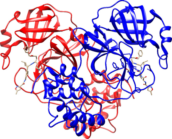
The main protease is a homodimer that cuts polyproteins into functional pieces for the production of new virons. Can metal ions inhibit this enzyme?
Highlights
-
•
Covid-19 disease is produced by SARS (Severe acute respiratory syndrome)-CoV-2.
-
•
Excluded volume in the folded SARS-CoV-2 main protease is estimated.
-
•
Helix stabilities in the SARS-CoV-2 main protease differ dramatically.
-
•
Metal ion binding could inhibit the SARS-CoV-2 main protease.
1. Introduction
Finding a therapeutic agent to treat COVID-19 is matter of great current interest. One target that has received much attention is the SARS (Severe acute respiratory syndrome)-CoV-2 main protease (Mpro) [[1], [2], [3], [4]]. Crystal structures of Mpro with inhibitor (PDB: 6LU7, [3]) and the unliganded protease (PDB: 6Y2E, [1]) have been determined (Fig. 1 ); and the rigidity and flexibility of Mpro have been investigated using pebble-game rigidity analysis, elastic network model normal mode analysis, and all-atom geometric simulations [5]. The protease is expected to display flexible motions that directly affect the geometry of a known inhibitor binding site, opening new binding sites elsewhere in the structure.
Fig. 1.
Chimera representation of the 6 LU7 Mpro monomer molecular structure. The ten helices are coded as follows: H1 (10–15) in magenta, H2 (41–44) in red, H3(53–60) in goldenrod, H4(62–66) in yellow, H5(200–214) in orange, H6(226–237) in brown, H7(243–250) in gray, H8(250–258) in violet red, H9(260–275) in blue, H10(292–301) in cyan. Hairpin section (150–165) in green.
We have employed a geometrical approach to analyze the structural stability of MPro. As in earlier work on helical proteins [6,7], the analysis is based on the coordinates reported for the 306 residues of the main protease monomer [3]. In connection with the analysis, we draw attention to histidines and cysteines that are in very stable regions of the native structure. Metal ion binding to one or more of these ligands likely would strongly inhibit the enzyme.
2. Spatial and angular signatures of helical and turning regions
The starting point in our approach is a triplet module of three residues, a center residue (i) flanked by its two first nearest neighbors (i − 1) and (i + 1). We define a coordinate system in which the crystallographic origin or a metal ion is assigned as the reference point. Using crystallographic data for a given protein, we calculate the distance R(i − 1) between the origin and the α-carbon of the left-most residue, the distance R(i + 1) to the right-most residue, and the distance R(i − 1 to i + 1) between the two α-carbons of the terminal residues. Also calculated from crystallographic data are the angles between R(i − 1) and R(i − 1 to i + 1), R(i − 1 ) and R(i + 1 ), and R(i − 1 to i + 1) and R(i + 1), designated α, β, γ, respectively. These signatures are compiled for each of the n residues of the protein. Analogous calculations have been carried out for sequences of five, seven, eleven and fifteen residues.
Continuing, we next calculate the distance T(i) between the terminal α-carbons [i − 2 to i + 2] for a configuration in which the triplet [i − 2, i − 1, i] is annexed to the triplet [i, i + 1, i + 2]. This planar configuration may be thought of as an unfolded state, as it is different from the native configuration. By construction, T(i) is greater than or equal to the native state distance, R(i − 2) to R(i + 2), so that for all residues i = 2 to i = n − 1 we have
Using the Law of Sines and Cosines, we established in previous work [6,7] that an exact analytical expression can be derived for the displacement of a central residue in a n-residue segment from an assigned reference point (crystallographic origin, metal ion) as the protein unfolds.
For example, consider the first five residues in a given protein. For the five-residue segment centered on residue 3, the displacement f 3 of residue 3 is given by
This expression for f 3 can be re-expressed exactly in an equivalent expression that is useful in interpreting the results obtained from our analysis. The proof is in Appendix 1 of [7]. This equivalence has been confirmed via direct calculation for all residues and all stages of unfolding for the investigated proteins.
Complementary to this ratio is the difference δ in distance (Å) of an n-residue linear extension of triplets minus the crystallographic distance between terminal α-carbons. We track the degree of unfolding in different protein regions by the increases in δ above 0. The largest values of δ in late unfolding stages identify protein regions where native and unfolded states exhibit the greatest differences.
3. Spatial signatures for unfolding of helical regions
In Table 1 are values of the average elongation ratio for each helical region in Mpro; results in this table can be compared with the values calculated for cytochrome c-b562 (cyt c-b562), cytochrome c’ (cyt c’), sperm whale myoglobin (sw-Mb) and human cytoglobin (h-Cyg) in Table 1 of [7]. Table 2 gives the values of the average distance difference δ (Å) for individual helices. For comparison, values of the average distance difference δ (Å) for individual helical regions in cyt c-b562, cyt c’, sw-Mb and h-Cyg are given in the Appendix (Table A1). Earlier we drew attention to the importance of excluded volume effects in the de novo synthesis of proteins [6]. These effects, the consequence of repulsive forces between and among the residues of a polypeptide chain, can be gauged by considering molecular volume data for the amino acids. Data for the helical regions of Mpro and four other proteins are given in Table 3 . Molecular volume data for helices having the same number of residues are given in Table A2.
Table 1.
Average elongation ratio for individual helical regions of Mpro. Number of residues in region in parentheses. Standard deviation is specified.
| Helix/ratio | ||||
|---|---|---|---|---|
| H1 | 1.52±0.26 | 1.46±0.12 | 1.44±0.13 | 1.44±0.05 |
| H2 | 1.28±0.14 | 1.34±0.09 | 1.63±0.45 | 1.67±0.17 |
| H3 | 1.56±0.27 | 1.50±0.15 | 1.73±0.27 | 2.07±0.28 |
| H4 | 1.41±0.37 | 1.44±0.13 | 1.50±0.28 | 1.58±0.09 |
| H5 | 1.68±0.25 | 1.70±0.27 | 1.78±0.43 | 1.96±0.55 |
| H6 | 1.69±0.23 | 1.76±0.32 | 2.27±1.05 | 2.76±0.97 |
| H7 | 1.60±0.28 | 1.59±0.09 | 1.70±0.19 | 1.81±0.15 |
| H8 | 1.61±0.28 | 1.88±0.55 | 2.26±0.71 | 3.17±1.36 |
| H9 | 1.69±0.34 | 1.66±0.15 | 1.83±0.14 | 2.16±0.44 |
| H10 | 1.70±0.37 | 1.62±0.11 | 1.75±0.14 | 1.92±0.10 |
Table 2.
Average distance difference δ (Å) for individual helical regions of Mpro. Number of residues in region in parentheses.
| Helix/δ | ||||
|---|---|---|---|---|
| T(i) − R(i − 2) to R(i + 2) | T(i) − R(i − 3) to R(i + 3) | T(i) − R(i − 5) to R(i + 5) | T(i) − R(i − 7) to R(i + 7) | |
| H1 | 3.68±01.26 | 5.37±0.86 | 8.94±1.69 | 13.04±1.13 |
| H2 | 2.46±1.01 | 4.45±0.90 | 10.48±4.48 | 16.82±2.43 |
| H3 | 3.78±1.61 | 5.58±1.21 | 11.89±2.20 | 20.66±2.73 |
| H4 | 3.08±2.07 | 5.45±1.28 | 9.60±3.45 | 15.48±1.45 |
| H5 | 4.22±1.28 | 6.55±1.42 | 12.20±4.72 | 17.82±4.82 |
| H6 | 4.37±1.28 | 7.11±1.53 | 14.45±3.89 | 24.47±4.66 |
| H7 | 3.89±1.64 | 6.24±0.84 | 11.40±1.77 | 17.76±1.95 |
| H8 | 4.03±1.29 | 7.42±2.12 | 14.76±3.47 | 25.08±5.05 |
| H9 | 4.22±1.63 | 6.58±1.01 | 12.58±1.37 | 20.51±3.72 |
| H10 | 4.32±1.84 | 6.52±0.77 | 12.28±1.35 | 19.65±1.42 |
Table 3.
Average molecular volume for helical regions. Number of residues in parentheses. See colors in Fig. 1: H1(magenta), H2(orange), H3(goldenrod), H4(yellow), H5(orange), H6(brown), H7(gray), H8(violet red), H9(blue), H10(cyan).
| Helix/Mol Vol(Å3) | ||||
|---|---|---|---|---|
| Mpro | cyt c-b562 | cyt c′ | sw-Mb | h-Cygb |
| H1 (6) | H1 (19) | H1 (25) | H1 (16) | H1 (17) |
| 109.37 | 136.97 | 136.64 | 145.47 | 138.76 |
| H2 (5) | H2 (20) | H2 (19) | H2 (17) | H2 (17) |
| 148.36 | 125.36 | 128.38 | 135.82 | 139.49 |
| H3 (7) | H3 (5) | H3 (3) | H3 (7) | H3 (7) |
| 153.84 | 139.82 | 122.67 | 142.01 | 140.89 |
| H4 (5) | H4 (27) | H4 (5) | H4 (7) | H4 (6) |
| 132.06 | 137.68 | 114.00 | 128.80 | 138.37 |
| H5 (15) | H5 (24) | H5 (6) | H5 (20) | H5 (21) |
| 141.22 | 133.99 | 157.17 | 132.03 | 131.38 |
| H6 (12) | H6 (23) | H6 (15) | H6 (19) | |
| 144.37 | 124.52 | 140.73 | 127.26 | |
| H7 (8) | H7 (24) | H7 (20) | H7 (20) | |
| 138.59 | 122.76 | 147.65 | 139.77 | |
| H8 (9) | H8 (26) | H8 (4) | ||
| 111.53 | 133.45 | 119.65 | ||
| H9 (16) | H9 (26) | |||
| 130.03 | 139.00 | |||
| H10 (10) | ||||
| 132.45 | ||||
4. Spatial signatures for unfolding of turning regions
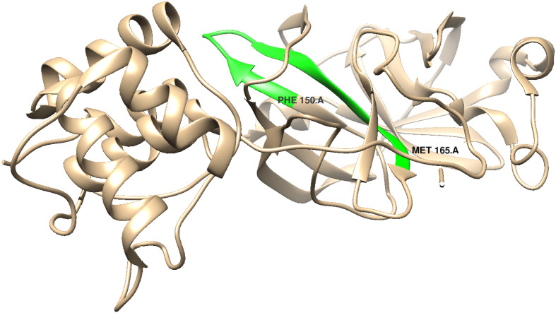
We focus attention on residues 16–40 and residues 67–199. Of special interest is the hairpin section (residues 150–165, in green in Fig. 1) in the extended (67–199) turning region.
In Fig. 2 are the distances (Å) of residues 16–40 from the crystallographic origin; the corresponding molecular volume (Å3) data are in Fig. 3 . The profile in Fig. 2 changes more- or-less smoothly with increase in residue number; that in Fig. 3 is more articulated. This difference will be a factor in later analyses.
Fig. 2.

Distances (Å) of residues 16–40 from the crystallographic origin. Flanking helical regions are included. Horizontal bar: average distance (68.446 Å) of 306 residues from the origin.
Fig. 3.
Molecular volumes (Å3) of residues 14–40. Flanking helical regions are included. Horizontal bar: average molecular volume of 306 residues (132.5 Å3).
We define a metric to give insight on the local neighborhood of each residue in the turning region 16–40. The average molecular volume (Å3) of each residue calculated with respect to its first-, second-, third-, fifth, and seventh-nearest neighbors is set out in Table 4 .
Table 4.
Residues 16–40. Average molecular volume (Å3) for nth nearest neighbors.
| Residue | Ratio | δ | First NN | Second NN | Third NN | Fifth NN | Seventh NN |
|---|---|---|---|---|---|---|---|
| 16 | 1.306 | 2.804 | 110.50 | 121.98 | 127.67 | 125.32 | 116.59 |
| 17 | 1.068 | 0.822 | 137.13 | 123.06 | 127.67 | 129.72 | 116.81 |
| 18 | 1.048 | 0.591 | 148.90 | 139.04 | 124.49 | 119.85 | 118.62 |
| 19 | 1.027 | 0.362 | 148.90 | 140.56 | 131. | 117.68 | 122.35 |
| 20 | 1.002 | 0.029 | 133.30 | 129.68 | 129.68 | 115.65 | 122.23 |
| 21 | 1.005 | 0.068 | 121.53 | 113. | 117.80 | 120.75 | 120.50 |
| 22 | 1.237 | 2.467 | 94.90 | 108.16 | 114.39 | 126.04 | 115.28 |
| 23 | 1.123 | 6.264 | 94.90 | 103.38 | 110.43 | 121.60 | 121.60 |
| 24 | 1.898 | 5.954 | 97.43 | 103.38 | 114.24 | 114.34 | 130.34 |
| 25 | 1.097 | 1.097 | 116.10 | 115.02 | 113.96 | 116.42 | 130.59 |
| 26 | 1.006 | 0.077 | 132.97 | 125.82 | 125.82 | 124.40 | 128.67 |
| 27 | 1.091 | 1.136 | 132.30 | 114.62 | 122.27 | 129.00 | 126.49 |
| 28 | 1.055 | 0.745 | 113.63 | 119.40 | 138.23 | 129.24 | 126.49 |
| 29 | 1.016 | 0.206 | 113.63 | 147.08 | 145.46 | 134.33 | 128.08 |
| 30 | 1.019 | 0.242 | 151.53 | 147. | 144.74 | 136.05 | 133.75 |
| 31 | 1.019 | 0.237 | 187.07 | 146.48 | 136.80 | 138.22 | 136.98 |
| 32 | 1.187 | 1.943 | 168.53 | 156.68 | 140.50 | 145.26 | 136.75 |
| 33 | 2.088 | 6.388 | 129.63 | 151.34 | 151.91 | 139.97 | 140.57 |
| 34 | 2.049 | 6.640 | 120.73 | 133.78 | 155.76 | 139.85 | 143.05 |
| 35 | 1.142 | 1.513 | 130.37 | 139.16 | 138.71 | 150.15 | 141.27 |
| 36 | 1.004 | 0.054 | 157.87 | 138.64 | 131.00 | 148.92 | 144.77 |
| 37 | 1.022 | 0.293 | 147.37 | 138.96 | 139.90 | 140.94 | 148.00 |
| 38 | 1.114 | 1.320 | 138.27 | 145.64 | 140.94 | 140.94 | 144.63 |
| 39 | 1.060 | 0.721 | 131.53 | 148.28 | 145.91 | 140.70 | 135. |
| 40 | 1.492 | 3.827 | 146. | 137.56 | 149.73 | 141.15 | 133.49 |
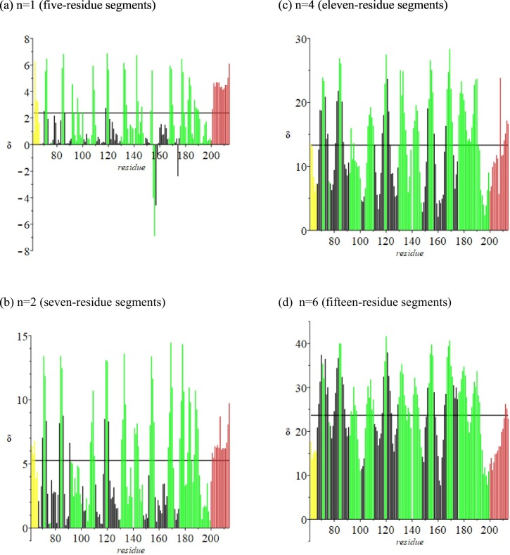
Also included are corresponding values of the spatial signature δ for the first unfolded state. These values change as the protein unfolds and the structural stability of the native protein is disrupted (Fig. 4 ). Residues coded in black denote amino acids that are in a beta segment. Notice that in the early stages of unfolding values of δ in the flanking helical regions are larger than those for residues in the turning region, but that this behavior is reversed as the protein continues to unfold. This “crossover” behavior also is found in the cytochromes and globins [6].
Fig. 4.
Linear extension of triplets minus crystallographic distance between terminal α-carbons in turning region (residues 16–40; δ in Å). Black denotes residues in a beta strand. Flanking helical regions are included (magenta, red). Green denotes turning regions. Horizontal line: average δ for 306 residues.
Fig. 5 is the profile of δ versus residue number for the Mpro extended turning region (67–199). In this figure the black vertical lines denote residues that are in one beta strand. Residues in this region are in multiple beta sheets; additional H-bond interactions are not shown.
Fig. 5.
Linear extension of triplets minus crystallographic distance between terminal α-carbons in the turning region (residues 67–199; δ in Å). Black denotes residues in one beta strand. Flanking helical regions are included. Green denotes turning regions. Horizontal line: average δ for 306 residues.
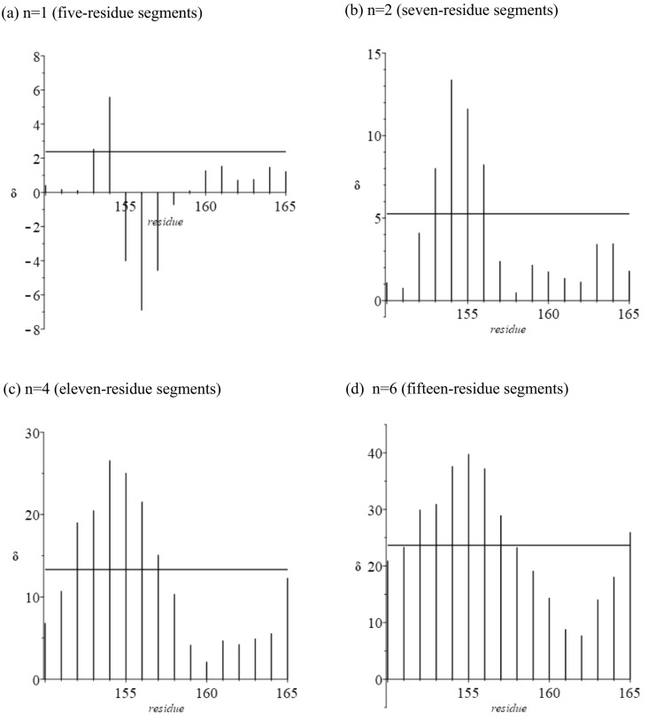
We now focus on hairpin residues 154–159 (Fig. 6, Fig. 7 ). Values of δ are for the first unfolded state (Table 5 ). The behavior of residues in this region is totally unlike that in later stages of folding, starting with the second. Moreover, nothing like this behavior is displayed by the cytochromes and globins. As adjacent segments are annealed the ratio is expected to be >1 (see discussion of these metrics in Section 2). Small negative values of δ (~−1) have been observed for Mb and cyt c-b562 (Ref [6], Fig. 3, Fig. 4) in the past, but never the very large values obtained here. We suggest that there might be an unusual backbone configuration in this region.
Fig. 6.
Hairpin region in Mpro (PDB ID: 6LU7).
Fig. 7.
Linear extension of triplets minus crystallographic distance between terminal α-carbons in the hairpin region (residues 154–159; δ in Å, See Fig. 1). Black denotes residues in a beta strand. Flanking helical regions are included. Horizontal line: average δ for 306 residues.
Table 5.
Hairpin region (residues 154–159, in green in Fig. 1)): average molecular volume (Å3) for nth nearest neighbors.
| Residue | Ratio | δ | First NN | Second NN | Third NN | Fifth NN | Seventh NN |
|---|---|---|---|---|---|---|---|
| 154 | 1.985 | 5.589 | 138.60 | 138.20 | 135.01 | 134.00 | 133.67 |
| 155 | 0.761 | −4.029 | 137.73 | 119.87 | 112.50 | 139.63 | 129.13 |
| 156 | 0.631 | −6.910 | 132.86 | 128.44 | 127.70 | 127.18 | 144.20 |
| 157 | 0.734 | −4.588 | 131.43 | 134.74 | 134.37 | 134.37 | 141.77 |
| 158 | 0.944 | −0.735 | 138.40 | 138.74 | 143.17 | 141.95 | 145.77 |
| 159 | 1.009 | 0.113 | 138.60 | 139.48 | 145.69 | 143.89 | 145.51 |
5. Correlation with Angular Signatures
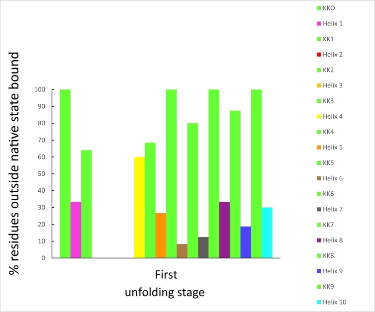
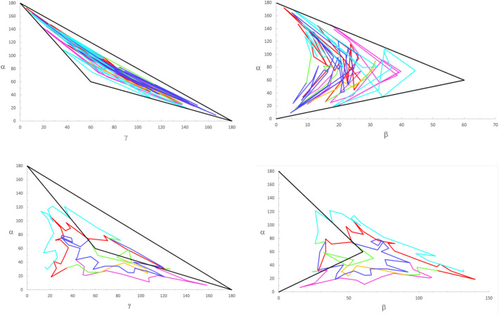
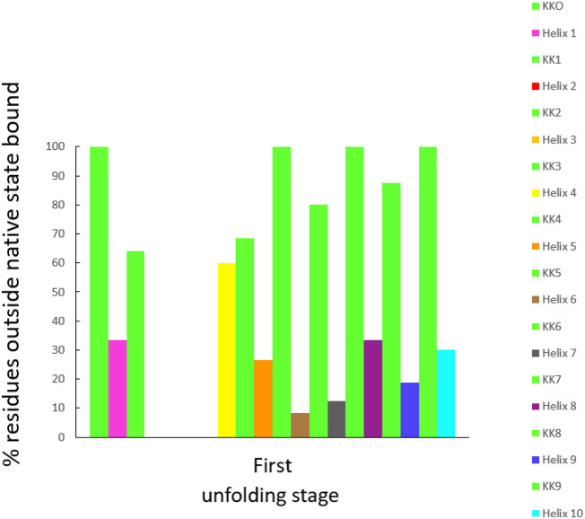
Out of the 477 hydrogen bonds calculated for a Mpro monomer in a crystal, 58% are formed between residues and the rest between residues and water molecules or between water molecules. One way to understand first-stage unfolding is to calculate the percent of residues outside the native state boundary using two angular domains: β vs α and γ vs α. We did not observe first- stage unfolding when we examined the γ vs α space, however, for β vs α space the situation was different. The percent of H-bonded residues outside the Mpro native state vs that of the first unfolding stage is shown in Fig. 8 (Fig. A1, Fig. A2, Fig. A3, Fig. A4 compare cyt c-b562 and Mpro native vs unfolded states).
Fig. 8.
Percent departure of helical and non-helical regions from the native state [β, α] Mpro domain.
It is of interest that most non-helical sections of Mpro unfold more readily than helical regions. However, two of the non-helical sections of the protease, namely KK2 and KK3, do not unfold at all while KK0, KK5, KK7 and KK9 are completely unfolded at this stage. KK1, KK4, KK6 and KK8 are partially unfolded, with values of 64, 68.4, 80 and 87.5%, respectively. Notably, neither Helix 2 nor Helix 3 unfolds; but 60% of Helix 4 unfolds, with many residues moving away from their positions in the native state. Helix 6 unfolds the least (8.33%), followed by Helix 7(12.5%), Helix 9 (18.75%), Helix 5 (26.55%), Helix 10 (30%), and ending with both Helix 1 and Helix 8 unfolding equally (33.3%). In summary, the order of unfolding in the protease is H6 < H7 < H9,H5 < H10 < (H1, H8) < H4.
6. Discussion
A seminal insight on the importance of excluded volume effects on the interaction between and among proteins in solution was presented by Kauzmann in 1959 [8]. Following earlier work by Edsall [9] and Flory [10], he noted that in the expression for the osmotic pressure of a protein as a power series in protein concentration, the second osmotic virial coefficient is directly related to the excluded volume of the protein. This insight was mobilized and extended in a study of solute-solute interactions in aqueous solution [11]. The effect of solute size on the second and third osmotic virial coefficients was investigated using the lattice theories of Flory [10], Huggins [12], Guggenheim and McGlashan [13] as well as McMillan and Mayer [14]. For a series of amino acids and peptides, conclusions were drawn after consideration of increasing aliphatic chain length; increasing the number of solute functional groups capable of participating in H-bond formation; and increasing the solute-molecule dipole moment.
Importantly, the role of atomic level steric effects and attractive forces in protein folding was first recognized and explored using molecular models by Lammert, Wolynes and Onuchic [15]. Using variants of their models that replaced the term for the unspecific repulsion by Weeks-Chandler-Andersen (WCA) potentials [16], the range and effectiveness of unspecific repulsive interactions and specific attractions between tertiary contact pairs were quantified to document their respective influence on the formation of native protein structure.
The importance of excluded volume effects in the turning regions of cytochromes and globins was highlighted in [6]. These effects, the consequence of repulsive forces between and among the residues of a polypeptide chain, can be gauged by considering amino-acid molecular volume data. Data for individual helical regions for the five proteins studied here are given in Table 3.
It is interesting to compare molecular volume data for helices having the same number of residues for the cytochromes, globins and Mpro (Table A2). Sometimes the molecular volumes are within a few Å3 and sometimes they differ by up to 20 Å3 for helices of the same length. The difference is possibly related to the number of PHE, TYR and TRP in helices of comparable length. (See Fig. 2 of [6]).
Calculating the average molecular volume for all residues in each of the proteins studied here, we obtain:
It is remarkable that when all residues in each protein are considered, the maximum spread in average values <V> for the five proteins is only ~10 Å3. By compiling a list of the percent of each amino acid in each of the five proteins, we discover that the above averages are a consequence of dominant contributions from six residues: ALA, ASP, GLU, LEU, LYS and VAL. In addition to these amino acids, Mpro has GLY as a “runner up.” It is noteworthy that the residues at the bottom of the “valley” in Fig. 3 are both GLY and the maximum “peak” is TRP 31. See Fig. 2 of [6]. We also have investigated a beta barrel blue copper protein, amicyanin [17]; here, <V> = 132.29 Å3. The primary sequence is mainly ALA, GLU, LYS, VAL, and GLY.
The calculated averages reflect the net influence of steric interactions between and among residues in the polypeptide chain. The data demonstrate that repulsive interactions are the dominating factor in determining native protein structures, whether they be helical or beta barrels, or, as in Mpro, a combination of these secondary structural elements. Although there are no metal ions in Mpro, unfolding its ten helices is characterized by signature δ values similar to those of the cytochromes and globins ([6], Table A1 and Table 2).
6.1. Metal-ion binding to Mpro
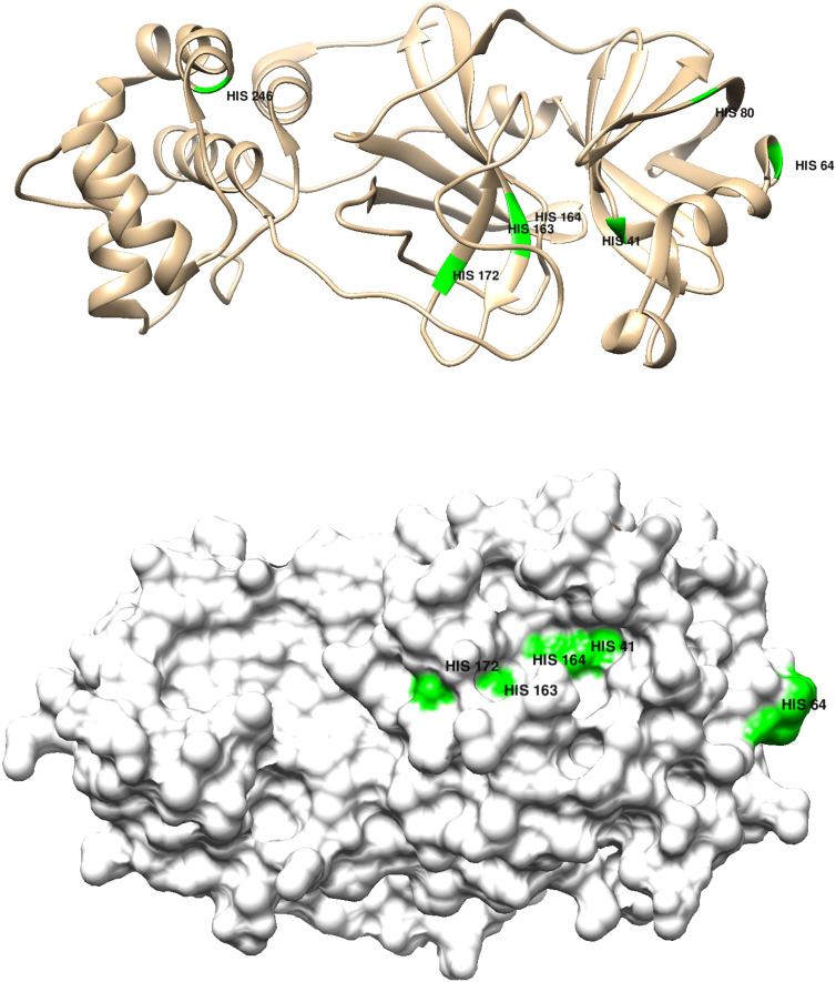
In seminal papers published well over fifty years ago, Kauzmann demonstrated that chemical additives could unfold protein structures [[18], [19], [20], [21], [22]]. Forty-five years later, we discovered that myoglobin readily unfolded upon addition of a Co(III) reagent; and that destabilization of the folded structure was attributable to Co(III)-His ligation [23]. Notably, like myoglobin, Mpro is histidine rich, suggesting that metal-ion binding might compromise protease function. It turns out that all seven Mpro(monomer) histidines are partially exposed at the surface (Fig. 9 ); and, according to our structural analysis, four (HIS 41, HIS 163, HIS 164, HIS 246) are in very stable regions where metal-ion binding could do the most damage.
Fig. 9.
Top panel: Chimera representation of the Mpro 6Y2E (apo) monomer structure showing the positions of the 7 histidine residues; bottom panel shows the degree of surface exposure of residues 41, 64, 163, 164, 172.
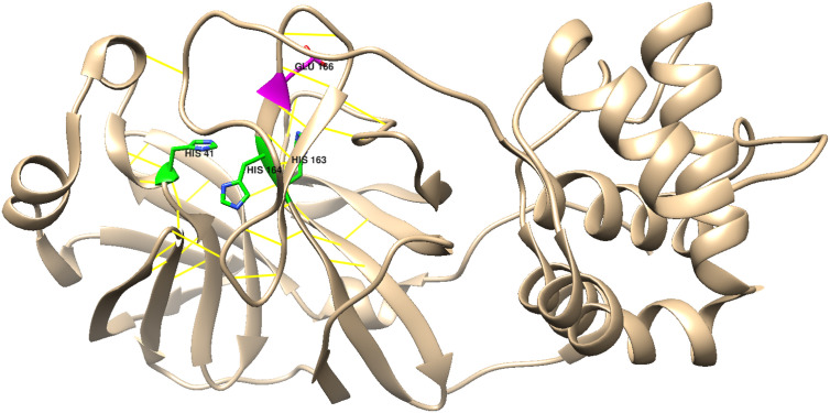
HIS 41, which is on Helix 2, is the most attractive target, as it is near Cys 145, the main active-site residue. Binding of metal ions to the imidazole side chain of this histidine likely would break up the active-site H-bond network (Fig. 10 ), which would disable the enzyme. Among the candidates that might bind to these residues, [Co(acacen)(NH3)2]+,(acacen=bis-acetylacetone-ethylenediimine), is arguably the metal ion of choice, as it is an effective inhibitor of other proteases; and it has been established that Co(III) binding occurs by His(imidazole) displacement of one or both axial ammines [24,25].
Fig. 10.
Chimera representation of the Mpro active-site H-bond network (yellow lines); His 41, His 163, His 164, and Glu 166 are highlighted (PDB code 6Y2E) [26,27].
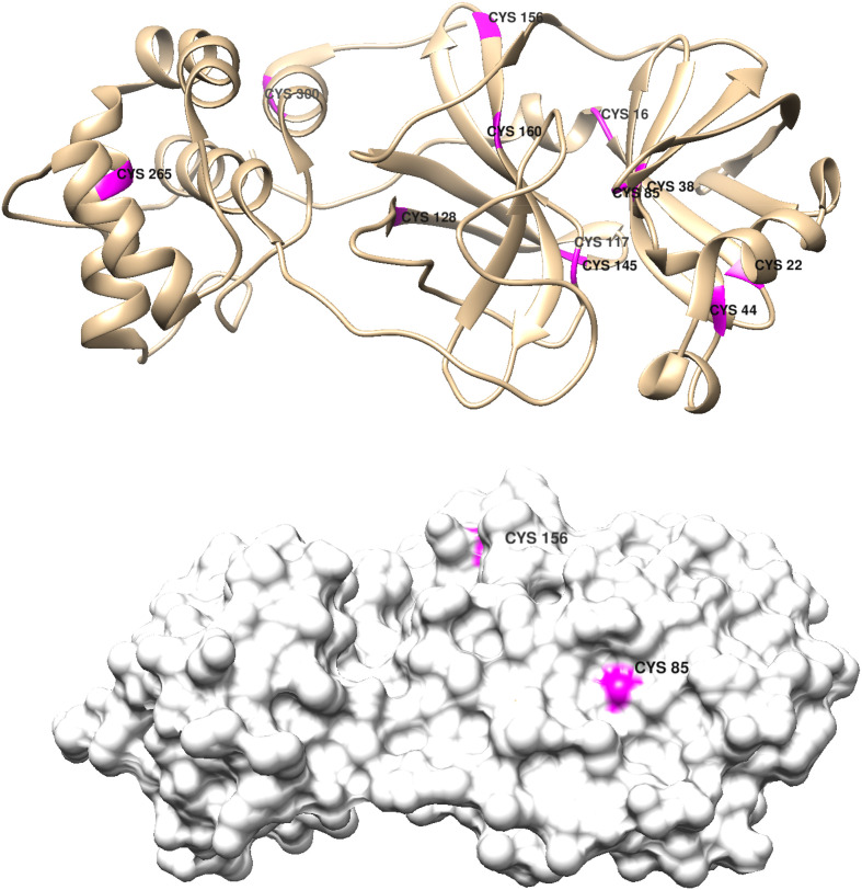
Cysteine ligation also should be explored; and there are 12 CYS residues in each Mpro monomer (Fig. 11 ).
Fig. 11.
Top panel: Chimera representation of the Mpro monomer structure showing the positions of the 12 cysteine residues; bottom panel shows the exposure of residues 85 and156. All other CYS residues are buried in the native structure (PDB code 6Y2E) [26,27].
The most attractive targets are CYS 44 and CYS 145. CYS 44 is on a very stable helix (Helix 2), and CYS 145 is an active-site residue. Irreversible replacement of an axial ammine in [Co(acacen)(NH3)2]+ by the CYS 145 thiolate would inhibit the protease, as it would block substrate access to the functional nucleophile. Binding to CYS 44 would trigger partial unfolding of Helix 2, which also could affect protease function.
In summary, based on our analysis of Mpro stability, we have identified regions where inorganic therapeutic agents could compromise the coronavirus by targeting histidines and/or cysteines. In one scenario, the main protease could be inhibited by Co(III) attachment to HIS 41; and in another, Co(III) binding to the active-site CYS 145 thiolate would be lethal to enzyme function.
Declaration of competing interest
The authors declare that they have no known competing financial interests or personal relationships that could have appeared to influence the work reported in this paper.
Acknowledgements
Work at Caltech was supported by the NIH (DK019038) and the Arnold and Mabel Beckman Foundation. Support at Pomona College was provided by the Howard Hughes Medical Institute Research Program and a Sontag Research Fellowship Award. Molecular graphics and analyses performed with UCSF Chimera, developed by the Resource for Biocomputing, Visualization, and Informatics at the University of California, San Francisco, with support from NIH P41-GM103311.
Appendix A.
Methods: molecular surfaces were calculated using the MSMS package embedded in Chimera [26,27].
Table A1.
Average distance difference δ (Å) of the protein for individual helical regions. Standard deviation is specified.
| Helix / δ | cyt c-b562 | cyt c′ | sw-Mb | h-Cygb |
|---|---|---|---|---|
| T(i) − R(i − 2) to R(i + 2) | ||||
| H1 | 4.38±1.19 | 4.28±0.86 | 4.25±1.23 | 4.48±1.21 |
| H2 | 4.58±0.75 | 4.31±1.16 | 4.58±1.28 | 4.61±1.25 |
| H3 | 3.23±2.20 | 3.49±0.82 | 3.14±0.74 | 2.56±0.71 |
| H4 | 4.50±0.63 | 2.90±1.54 | 4.24±1.11 | 3.92±1.08 |
| H5 | 3.97±1.43 | 3.40±2.07 | 4.31±0.92 | 4.46±0.98 |
| H6 | 4.27±1.09 | 4.84±1.79 | 4.89±1.23 | |
| H7 | 4.55±1.17 | 4.37±1.43 | 4.32±1.22 | |
| H8 | 4.72±0.79 | 2.97±2.03 | ||
| H9 | 3.44±2.58 | |||
| T(i) − R(i − 3) to R(i + 3) | ||||
| H1 | 6.51±0.89 | 6.44±1.14 | 6.43±0.64 | 6.52±0.87 |
| H2 | 6.74±1.31 | 6.39±0.43 | 7.06±1.26 | 7.05±1.11 |
| H3 | 6.81±1.29 | 4.39±0.25 | 6.16±2.64 | 5.55±2.59 |
| H4 | 6.70±1.01 | 5.36±1.14 | 7.16±2.19 | 6.85±2.05 |
| H5 | 5.88±0.85 | 4.99±1.03 | 6.55±1.01 | 6.80±1.13 |
| H6 | 6.43±0.70 | 7.07±1.89 | 7.35±1.64 | |
| H7 | 6.97±1.83 | 6.52±0.75 | 6.28±0.74 | |
| H8 | 6.70±0.51 | 5.68±1.72 | ||
| H9 | 6.69±0.68 | |||
| T(i) − R(i − 5) to R(i + 5) | ||||
| H1 | 12.50±2.12 | 12.39±2.65 | 11.83±1.45 | 12.57±1.75 |
| H2 | 12.96±2.92 | 11.67±1.13 | 13.48±2.34 | 13.35±2.10 |
| H3 | 16.21±3.41 | 8.84±1.20 | 14.40±3.15 | 15.16±3.49 |
| H4 | 12.70±1.94 | 12.86±3.46 | 15.81±2.17 | 15.90±2.03 |
| H5 | 11.58±2.52 | 11.60±3.16 | 12.29±1.64 | 12.40±1.37 |
| H6 | 12.28±1.82 | 13.58±2.65 | 13.99±2.43 | |
| H7 | 13.34±3.36 | 12.43±2.13 | 11.97±1.73 | |
| H8 | 12.59±1.03 | 16.16±0.45 | ||
| H9 | 12.83±1.75 | |||
| T(i) − R(i − 7) to R(i + 7) | ||||
| H1 | 19.91±4.70 | 18.28±3.78 | 18.04±2.51 | 18.57±2.36 |
| H2 | 19.90±5.17 | 17.59±3.08 | 20.84±3.43 | 20.54±3.10 |
| H3 | 25.40±2.23 | 15.89±0.61 | 25.91±2.62 | 26.63±3.07 |
| H4 | 19.37±3.92 | 22.78±4.71 | 27.06±3.38 | 28.63±3.90 |
| H5 | 17.98±4.80 | 20.63±2.59 | 18.49±2.35 | 19.03±2.97 |
| H6 | 19.01±3.50 | 21.48±3.82 | 21.95±4.50 | |
| H7 | 21.01±5.97 | 19.72±4.14 | 18.77±3.49 | |
| H8 | 18.74±2.50 | 27.65±0.65 | ||
| H9 | 19.49±3.20 | |||
Table A2.
Average molecular volume (Å3) for helical regions as a function of helical length. Comparison with respect to chain length.
| (a) Mpro | (b) cyt c-b562 | (c) cyt c’ | (d) sw-Mb | (e) h-Cygb | |||
|---|---|---|---|---|---|---|---|
| H10 | (10) | 132.45a | |||||
| H6 | (12) | 144.37a | |||||
| H5 | (15) | 141.22a | H6 | (15) | 140.73d | ||
| H9 | (16) | 130.03d | H1 | (16) | 145.47d | ||
| H2 | (17) | 135.82d | H1 | (17) | 138.76e | H2 (17) 139.49e | |
| H1 | (19) | 136.97a | H2 | (19) | 128.38c | H6 (19) 127.26e | |
| H2 | (20) | 125.36b | H5 | (20) | 132.03d | H7 (20) 147.65d | H7 (20) 139.77e |
| H5 | (21) | 131.38e | |||||
| H6 | (23) | 124.52c | |||||
| H5 | (24) | 133.99b | H7 | (24) | 122.76c | ||
| H1 | (25) | 136.64c | |||||
| H8 | (26) | 133.45d | H9 | (26) | 139.00e | ||
| H4 | (27) | 137.68b | |||||
Fig. A1.
Angle phase diagrams for cyt c-b562, (top): {γ vs α} and {β vs α} native states, (bottom): {γ vs α} and {β vs α} sixth extended states.
Fig. A2.
Percent departure of helical and non-helical regions from native state[γ, α] domain: cyt c-b562, (left). Percent departure of helical and non-helical regions from native state [β, α] domain (right).
Fig. A1 shows how the different helical and non-helical regions leave the [γ, α] and [β, α] native states represented by the black triangle. Fig. A2 accounts quantitatively for this departure by the percent of residues outside the native state.
Fig. A3.
Angle phase diagrams for Mpro (left): {β vs α} native states, (right): {β vs α} first extended state.
Fig. A4.
Percent departure of helical and non-helical regions from native state [β, α] domain: Mpro.
Fig. A3 shows how the different helical and non-helical regions leave the [β, α] native state represented by the black triangle. Fig. A4 accounts quantitatively for this departure by the percent of residues outside the native state.
References
- 1.Zhang L., Lin D., Sun X., Curth U., Drosten C., Sauerhering L., Becker S., Rox K., Hilgenfeld R. Crystal structure of SARS-CoV-2 main protease provides a basis for design of improved a-ketoamide inhibitors. Science. 2020;368:409–412. doi: 10.1126/science.abb3405. [DOI] [PMC free article] [PubMed] [Google Scholar]
- 2.Hatada R., Okuwaki K., Mochizuki Y., Fukuzawa K., Komeiji Y., Okiyama Y. Fragment molecular orbital based interaction analyses on COVID-19 main protease - inhibitor N3 complex (PDB ID:6LU7) J. Chem. Inf. Model. 2020 doi: 10.1021/acs.jcim.0c00283. [DOI] [PubMed] [Google Scholar]
- 3.Jin Z., Du X., Xu Y. Structure of Mpro from SARS-CoV-2 and discovery of its inhibitors. Nature. 2020;582:289–293. doi: 10.1038/s41586-020-2223-y. [DOI] [PubMed] [Google Scholar]
- 4.Durdagi S., Aksoydan B., Dogan B., Sahin K., Shahraki A. 2020. Screening of Clinically Approved and Investigation Drugs as Potential Inhibitors of COVID-19 Main Protease: A Virtual Drug Repurposing Study. ChemRxiv. [DOI] [Google Scholar]
- 5.Wells S.A. Rigidity, normal modes and flexible motion of a SARS-CoV-2 (COVID-19) protease structure. bioRxiv. 2020 doi: 10.1101/2020.03.10.986190. [DOI] [Google Scholar]
- 6.Kozak J.J., Gray H.B. Stereochemistry of residues in turning regions of helical proteins. J. Biol. Inorg. Chem. 2019;24:879–888. doi: 10.1007/s00775-019-01696-9. [DOI] [PubMed] [Google Scholar]
- 7.Kozak J.J., Gray H.B., Garza-Lopez R.A. Funneled angle landscapes for helical proteins. J. Inorg. Biochem. 2020;208:111091. doi: 10.1016/j.jinorgbio.2020.111091. [DOI] [PMC free article] [PubMed] [Google Scholar]
- 8.Kauzmann W. Some factors in the interpretation of protein denaturation. Adv. Protein Chem. 1959;14:1–63. doi: 10.1016/s0065-3233(08)60608-7. [DOI] [PubMed] [Google Scholar]
- 9.Edsall J.T. In: The Proteins. Neurath H., Bailey K., editors. vol.I. Academic Press; New York: 1953. Part B, Chapter 7. [Google Scholar]
- 10.Flory P. Cornell Univ. Press; Ithaca, New York: 1953. Principles of Polymer Chemistry. Chapter 14. [Google Scholar]
- 11.Kozak J.J., Knight W.S., Kauzmann W. Solute-solute interactions in aqueous solution. J. Chem. Phys. 1968;48:675–690. [Google Scholar]
- 12.Huggins M.L. Solutions of long chain compounds. J. Chem. Phys. 1941;9:440–450. [Google Scholar]
- 13.Guggenheim E.A., McGlashan M.L. Statistical mechanics of regular mixtures. Proc Roy Soc A. 1951;206:335–345. [Google Scholar]
- 14.McMillan W., Jr., Mayer J.E. The statistical thermodynamics of multicomponent systems. J. Chem. Phys. 1945;13:276–290. [Google Scholar]
- 15.Lammert H., Wolynes P.G., Onuchic J.N. Attractive forces in protein folding. Steric effects and attractive forces. Proteins. 2012;80:362–373. doi: 10.1002/prot.23187. [DOI] [PMC free article] [PubMed] [Google Scholar]
- 16.Weeks J.D., Chandler D., Andersen H.C. Role of repulsive forces in determining the equilibrium structure of simple liquids. J. Chem. Phys. 1971;54:5237–5247. [Google Scholar]
- 17.Kozak J.J., Gray H.B., Wittung-Stafshede P. Geometrical description of protein structural motifs. J. Phys. Chem. 2018;122:11289–11294. doi: 10.1021/acs.jpcb.8b07130. [DOI] [PubMed] [Google Scholar]
- 18.Simpson R.B., Kauzmann W. Kinetics of protein denaturation. I. Behavior of the optical rotation of ovalbumin in urea solutions. J. Am. Chem. Soc. 1953;75:5139–5152. [Google Scholar]
- 19.Schellman J., Simpson R.B., Kauzmann W. Kinetics of protein denaturation. II. Optical rotation of ovalbumin in solutions of guanidinium salts. J. Am. Chem. Soc. 1953;75:5152–5154. [Google Scholar]
- 20.Frensdorff H.K., Watson M.T., Kauzmann W. Kinetics of protein denaturation. IV. Viscosity and gelation of urea solutions of ovalbumin. J. Am. Chem. Soc. 1953;75:5157–5166. [Google Scholar]
- 21.Frensdorff H.K., Watson M.T., Kauzmann W. Kinetics of protein denaturation. V. Viscosity of urea solutions of serum albumin. J. Am. Chem. Soc. 1953;75:5167–5172. [Google Scholar]
- 22.Kauzmann W., Simpson R.B. Kinetics of protein denaturation. III. Optical rotations of serum albumin, beta-lactoglobulin, and pepsin in urea solutions. J. Am. Chem. Soc. 1953;75:5154–5157. [Google Scholar]
- 23.Blum O., Haiek A., Cwikel D., Dori Z., Meade T.J., Gray H.B. Isolation of a myoglobin molten globule by selective cobalt(III)-induced unfolding. Proc. Natl. Acad. Sci. U. S. A. 1998;95:6659–6662. doi: 10.1073/pnas.95.12.6659. [DOI] [PMC free article] [PubMed] [Google Scholar]
- 24.Takeuchi T., Böttcher A., Quezada C.M., Simon M.I., Meade T.J., Gray H.B. Selective inhibition of human α-thrombin by cobalt(III) Schiff base complexes. J. Am. Chem. Soc. 1998;120:8555–8556. [Google Scholar]
- 25.Böttcher A., Takeuchi T., Hardcastle K.I., Meade T.J., Gray H.B., Cwikel D., Kapon M., Dori Z. Spectroscopy and electrochemistry of cobalt(III) Schiff base complexes. Inorg. Chem. 1997;36:2498–2504. [Google Scholar]
- 26.Sanner M.F., Olson A.J., Spehner J.C. Reduced surface: an efficient way to compute molecular surfaces. Biopolymers. 1996;38:305–320. doi: 10.1002/(SICI)1097-0282(199603)38:3%3C305::AID-BIP4%3E3.0.CO;2-Y. [DOI] [PubMed] [Google Scholar]
- 27.Pettersen E.F., Goddard T.D., Huang C.C., Couch G.S., Greenblatt D.M., Meng E.C., Ferrin T.E. UCSF chimera—a visualization system for exploratory research and analysis. J. Comput. Chem. 2004:1605–1612. doi: 10.1002/jcc.20084. [DOI] [PubMed] [Google Scholar]


