

Abstract
Objective:
Deep anterior lamellar keratoplasty (DALK) significantly reduces the post-transplantation morbidity in patients eligible for partial-thickness cornea grafts. The popular “big bubble” technique for DALK is so challenging, however, that a significant fraction of corneal pneumodissection attempts fail for surgeons without extensive DALK-specific experience, even with previous-generation cross-sectional optical coherence tomography (OCT) guidance. We seek to develop robotic, volumetric OCT-guided technology capable of facilitating or automating the difficult needle insertion step in DALK.
Methods:
Our system provides for real-time volumetric corneal imaging, segmentation, and tracking of the needle insertion to display feedback for surgeons and to generate needle insertion plans for robotic execution. We include a non-automatic mode for cooperative needle control for stabilization and tremor attenuation, and an automatic mode in which needle insertion plans are generated based on OCT tracking results and executed under surgeon holdto-run control by the robot arm. We evaluated and compared freehand, volumetric OCT-guided, cooperative, and automatic needle insertion approaches in terms of perforation rate and final needle depth in an ex vivo human cornea model.
Results:
Volumetric OCT visualization reduces cornea perforations and beneficially increases final needle depth in manual insertions by clinically significant amounts. Our automatic robotic needle insertion techniques meet or exceed surgeon performance in both needle placement and perforation rate.
Conclusion:
Volumetric OCT is a key enabler for surgeons, although robotic techniques can reliably replicate their performance.
Significance:
Robotic needle control and volumetric OCT promise to improve outcomes in DALK.
Index Terms—: Medical robotics, deep anterior lamellar keratoplasty, optical coherence tomography, cooperative control
I. Introduction
DEEP anterior lamellar keratoplasty (DALK) is a promising technique for cornea transplantation which significantly improves the morbidity associated with full-thickness cornea grafts (Fig. 1). In contrast to penetrating keratoplasty (PKP), DALK only transplants the superficial 90+% of the cornea, including the epithelium and ideally nearly all of the stroma (Fig. 1). When retaining the host cornea’s endothelium in DALK, the patient experiences reduced risks of allograft rejection and traumatic eye rupture [1]. Despite DALK’s advantages for patients, the popular “big bubble” technique [2] is challenging for surgeons, requiring them to carefully approach the endothelium within 50 μm while advancing a needle (or cannula) from the cornea’s paracentral zone to its apex. A trephination is commonly performed beforehand, to provide a depth-controlled incision from which to start the insertion, but is not necessary for a successful outcome [3]–[7]. Air is then injected via the needle to separate the stroma from the endothelium by pneumodissection, the success of which correlates with needle depth [8]. This presents nontrivial hurdles in not only visualizing needle tip depth with an overhead surgical microscope but also in optimally controlling the needle insertions by hand. DALK consequently fails in 15–59% of attempts, depending on surgeon and technique, due to corneal perforation or inadequate stromal dissection [9], [10].
Fig. 1.
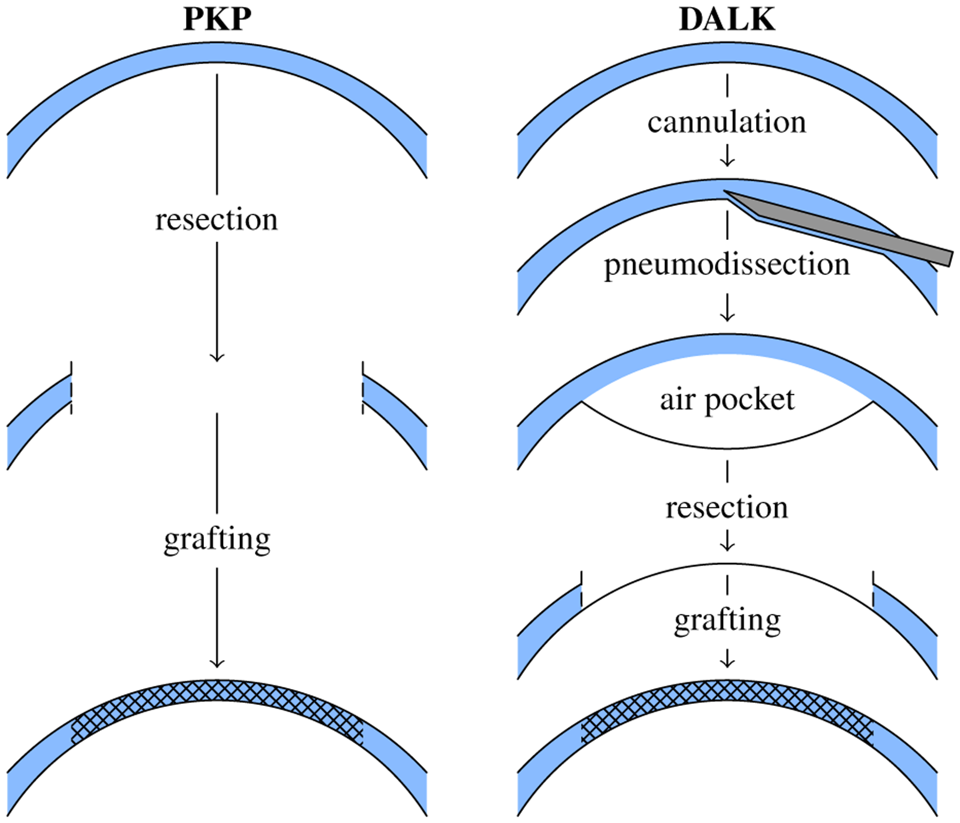
Penetrating keratoplasty (PKP) performs full-thickness resection and grafting (left). In contrast, deep anterior lamellar keratoplasty (DALK) performs a pneumodissection-aided partial thickness resection that spares the endothelium (right).
Corneal surgeons have turned to intraoperative optical coherence tomography (OCT) as a quantitative cross-sectional imaging modality for improved needle depth visualization [11]–[14]. Rather than relying on depth perception and visual cues, surgeons equipped with OCT directly measure the corneal thickness below the needle in cross-sections (B-scans) containing the needle tip. In most cases, OCT is reserved for pauses during the procedure due to slow acquisition times and shadowing present underneath the needle. Depth measurement is subsequently performed with the needle withdrawn to reveal the insertion tract and the corneal stroma underneath. This limitation is overcome by either inpainting the shadow [15] or introducing an endothelial-facing OCT probe into the needle itself [16], [17]. These techniques are not widespread, however.
Even with intraoperative OCT B-scans for guidance, 30% of DALK attempts still fail [14]. Incomplete pneumodissection due to insufficient needle depth accounts for nearly all failures; only 1% fail due to corneal perforation [14]. Unsurprisingly, remaining corneal thickness (i.e., the complement of needle depth) differentiates pneumodissection successes and failures. In successes, surgeons reach 90.4±27.7 μm (mean ± std. dev.) of remaining stroma whereas in failures, surgeons stop short with 136.7±24.2 μm of stroma remaining, as measured with intraoperative OCT [14]. Thus, needle insertions that are even 50 μm too shallow reliably yield incomplete pneumodissections [8], [14]. Moreover, the 95% spread of OCT-guided DALK insertion depths is approximately 132 μm or 25% of corneal thickness [14], [15]. Failed pneumodissection should therefore be expected when surgeons target an average needle depth of 80% corneal thickness.
In contrast, high-speed volumetric OCT facilitates live intraoperative use by acquiring B-scans ten or more times faster [18]–[20], allowing surgeons to monitor instruments and/or tissues of interest in real-time [21]–[24]. By sweeping these B-scans over space, such systems can leverage their extra speed to assemble an OCT volume at a refresh rate suitable for practical use. In particular, next-generation systems integrated into surgical microscopes [25], [26] promise to provide improved intraoperative visualization for DALK by imaging the complete corneal surface. Such volumetric acquisitions permit 3D index-corrected reconstruction of the anterior and posterior corneal surfaces and subsequent inpainting for needle shadow removal [15].
Improved visualization with OCT only partially addresses the challenges surgeons face in DALK, however. Surgeons still must carefully guide the needle to the correct depth by hand, plagued by physiologic tremor [27], poor positioning accuracy [28], [29], and reaction forces routinely below sensation thresholds [30]. Multiple robotic approaches have emerged to mitigate these limitations. These include handheld robotic tools [31], [32], cooperative robots that jointly hold the tool with the surgeon [33]–[35], and teleoperated robots that completely separate the surgeon from the tool [36]–[38]. These latter two schemes permit full automation of ophthalmic procedures because the tool is independently supported by the robot. Notably, two of these systems have recently performed vitreoretinal procedures in human eye surgery [39], [40]. Other than lens phacoemulsification [41], progress has been less rapid in corneal procedures.
We present an image-guided, robot-assisted DALK system that features integrated volumetric OCT for live visualization and a cooperative robot to stabilize needle insertions [42]. We then extend this approach with fully automatic, OCT-guided robot needle insertions. Using a well-validated ex vivo human cornea model [8], [43], we directly compare freehand, OCT-guided, cooperative, and automatic needle insertions in terms of perforation rate and final needle depth. With our system, surgeons demonstrate an improvement in perforation-free needle depth compared to freehand insertions without OCT guidance, the current surgical standard. Furthermore, we demonstrate automatic techniques that meet or exceed surgeon performance in both needle placement and perforation rate.
II. Dalk Workstation
The DALK workstation consists of manipulation and visualization subsystems for imaged-guided needle control (Fig. 2). A computer couples the two subsystems in software based on the selected operating mode.
Fig. 2.

Assembled DALK workstation with operator console (left), surgeon station (center), and robot arm (right).
A. Manipulation Subsystem
The manipulation subsystem’s primary component is an IRB 120 robot arm (ABB Robotics; Shanghai, China) which has ±10μm repeatability over a 1m3 workspace appropriate for DALK. The robot held the cannulation needle using an ergonomic “DALK handpiece” custom designed to avoid mechanical interference with patient anatomy (e.g., the orbit) and the overhead microscope (Fig. 3). The handpiece mounted rigidly to the robot arm’s end-effector via a Gamma force/torque sensor (ATI Industrial Automation; Apex, NC) which provided the force/torque signal for cooperative control (Section II-D).
Fig. 3.
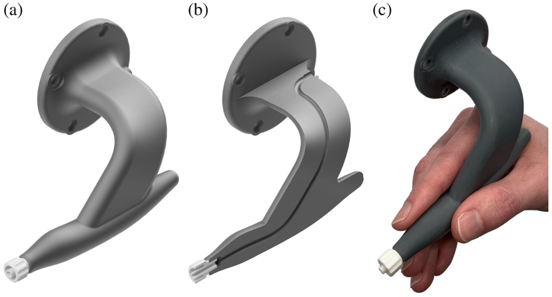
Ergonomic DALK handle with contoured grip (a) and internal channel for pneumodissection (b). Pencil-style hand grip that transfers immediately from surgical practice (c).
On its patient-facing end, the handpiece provided a quick-turn adapter for connection to standard medical needles. An internal channel connected the quick-turn adapter with a surgeon-facing port near the handpiece’s base for use in pneumodissection. We used disposable needles with a 30–45° bend at the hub as is common in surgical practice. To compensate for variability in needle mounting and bending, we calibrated the needle tip’s pose in the robot’s end-effector frame after each needle change using the procedure in Section II-F.
B. Visualization Subsystem
The visualization subsystem consisted of a custom telecentric OCT scanner suspended below a stereo microscope (Fig. 4). The scanner inserted the OCT light into the microscope’s infinity space using a dichroic mirror placed before the objective. We introduced the OCT light from behind the microscope to maximize the clear aperture for its oculars. In particular, the operator retained their full field of view at zoom levels typical for DALK. To improve OCT transmission, we replaced the microscope’s apochromatic objective with a pair of achromatic doublets optimized for OCT performance. At an appropriate magnification for DALK, these lenses degraded the microscope’s visible light resolution from 20 μm to 55 μm, approximately an eighth of a 27-gauge needle diameter. This modified objective provided a 93mm working distance for clearance of surgical tools, including robot-mounted ones. The dichroic insertion and modified objective added 6 cm of stack height, although the microscope remained comfortable to use.
Fig. 4.
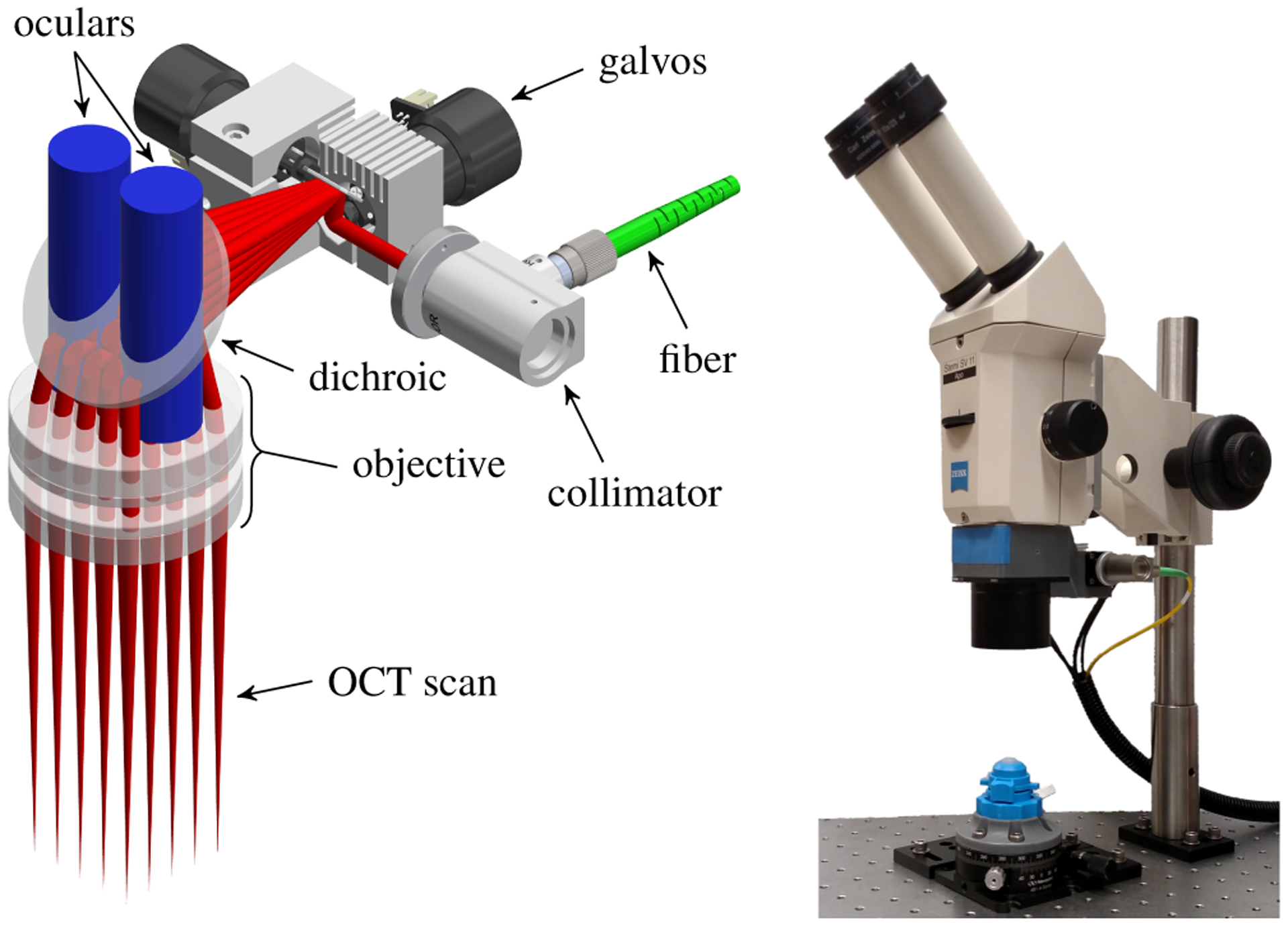
Design of microscope-integrated anterior segment scanner (left) illustrating stereo ocular view (blue) and 30×30mm OCT scan (red). Assembled scanner suspended below stereo microscope (right) with view of phantom cornea in artificial anterior chamber.
We optimized the scanner’s optical design in OpticStudio (Zemax; Kirkland, WA) over a 30mm lateral field of view. This obtained a theoretical lateral resolution of 32 μm, limited by the galvanometer mirror clear aperture and the long working distance. We assembled the scanner using a 3D printed backbone that positioned all optics according to the optimization results. The scanner mated to the microscope by replicating the stock objective’s dovetail.
The associated OCT engine (Fig. 5) featured a 1060nm swept frequency source (Axsun Technologies; Billerica, MA) with 100 nm bandwidth at a 100 kHz A-scan rate. The detection chain used a 800MSs−1 digitizer (AlazarTech; Quebec, Canada) to measure the output of a balanced photoreceiver (Thorlabs; Newton, NJ). The resulting imaging depth of 7.35mm was sufficient to visualize the cornea from apex to limbus. Using this engine, we acquired 96×800×1326 vx volumes over a 8×12×7.35mm region at a 0.8Hz volume rate. This acquisition protocol yielded a resolution of 83×15×5 μm in the slow lateral, fast lateral, and axial dimensions, respectively. We chose a fixed fast scan axis to align with expected needle shaft orientations during DALK to maximize B-scan suitability for needle depth measurement.
Fig. 5.

OCT engine schematic with transmissive reference arm and balanced detection (BD). PC, polarization controller. FC, fiber collimator.
C. Cornea Segmentation and Needle Tracking
We implemented live cornea segmentation and needle tracking as in [15] to guide automatic needle insertions. This segmentation approach used Dijkstra’s algorithm to trace the anterior and posterior corneal edges in OCT B-scans [44], [45]. We constructed a graph in which each B-scan pixel was a vertex and where each pixel was connected to its five neighbors (excluding the left-sided ones) with gradient-weighted edges. The anterior segmentation search was constrained based on an initial guess obtained by fitting a parabola to B-scan’s gradient image whereas the posterior segmentation search was constrained to avoid the anterior segmentation by a distance based on the mean human cornea thickness. Both segmentations from each B-scan were stacked along the volume’s slow axis to yield segmented corneal surfaces. Furthermore, we corrected the posterior surface for the index of refraction change across the anterior corneal surface [46], [47]. We estimated the cornea apex using the vertex of a paraboloid fit to the posterior corneal surface.
Our needle tracking algorithm fit a 3D model using the iterative closest point algorithm [48] to OCT voxels identified as corresponding to the needle. We chose these voxels by considering the brightest voxel in each A-scan (i.e., the summed voxel projection) that exceeded a threshold. The largest line-shaped cluster of these bright voxels that was oriented towards the cornea apex was selected for model fitting. This model fitting approach reduced the influence of individual voxels and consequently conferred resistance to saturation artifact that occasionally affected small portions the needle. Tool voxels identified below the anterior corneal surface were index corrected before fitting. Once the needle was tracked, inpainting [49] was used to correct the segmentation shadowed underneath the needle. These procedures were performed in real-time on a per-volume basis. In addition, we used needle tracking to calibrate the OCT coordinate system and the robot’s needle tip transform (Section II-F).
D. Cooperative Mode
Cooperative mode was implemented according to our prior work from [42]. In brief, raw force and torque measurements were conditioned to remove bias.
| (1) |
| (2) |
where m and are the tool mass and center-of-mass displacement from the measurement origin, respectively, Rb is the sensor pose at biasing, R is the sensor pose at measuring, and is gravitational acceleration. The gravitational force was then eliminated to yield the cooperative control force and torque .
| (3) |
| (4) |
After low-pass filtering, this force and torque drove a Cartesian force-velocity control law to yield cooperative control.
| (5) |
where is the target joint velocity vector, J(q) is the robot Jacobian about the tool center of rotation, H is the rotation matrix that defines the gain axes in the robot tool frame R, and G is the diagonal gain matrix. Cooperative activation was governed by a foot pedal. When released, the control software halted robot motion; when depressed, the control software executed the above control law.
E. Automatic Mode
In automatic mode, the DALK workstation generated needle insertion plans based on OCT segmentation and tracking results and then executed those plans under surgeon hold-to-run control using the robot arm [50]. Insertions were performed in two phases: embedding and advancement.
First, the needle embedding phase sought to introduce the needle into the corneal stroma without requiring trephination in advance (Fig. 6). By avoiding trephination, we eliminated the additional surgical instruments needed to open the incision for the needle. The robot first positioned the needle tip 3–4mm lateral to the apex on the epithelium with a 45–60° tilt away from the surface normal. Next, the needle was pressed 0.5mm posteriorly, deforming the cornea and gaining tissue purchase, and inserted 1mm along its shaft into the stroma. Then, the needle tip was lifted 0.5mm anteriorly, allowing the cornea to resume its normal shape, and pivoted about its tip to aim at the apex. The resulting U-shaped trajectory was executed open-loop yet reliably embedded the needle within the stroma in preparation for needle advancement.
Fig. 6.
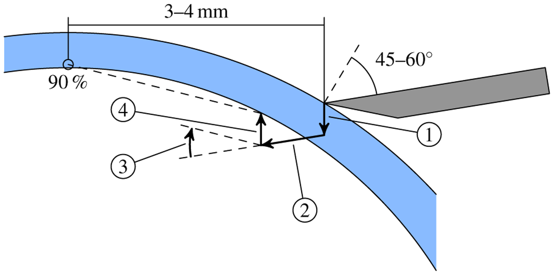
Illustration of the automatic mode embedding strategy. From the initial pose (gray needle), the robot depresses and advances the tip along segments 1 and 2, respectively. Segment 3 reorients the shaft to aim at the target (90% depth above the apex) after the elevation in segment 4. The cornea (blue) is rarely punctured during embedding due to deformation.
Next, the needle advancement phase sought to position the needle tip at the target depth above the apex without perforating the cornea (Fig. 7). This was accomplished by a selection of planners that used different advancement strategies. The “line” planner aimed the needle towards the target and advanced the tip in a straight line. If the needle shaft deviated more than 10° from the path tangent, advancement along the path was paused while the needle was reoriented about its tip. For deviations under 10°, the needle was reoriented while it advanced. The “cubic” planner advanced the needle along a cubic spline trajectory that leveled off the needle at the target position. The needle shaft was tangent to the path along the entire trajectory, including the initial waypoint. Both planners generated a complete trajectory from the current needle tip to the goal above the apex.
Fig. 7.
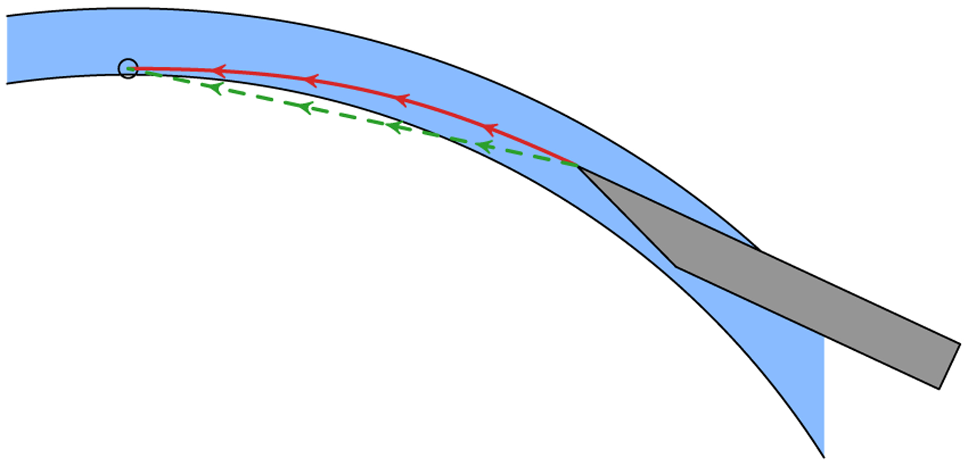
Illustration of the line (dashed, green) and cubic (solid, red) needle advancement trajectories with arrows indicating shaft orientation. For the line planner, the needle shaft is roughly oriented along the path before advancing. The cornea (blue) is not routinely punctured because it deforms as the needle advances. For the cubic planner, the needle shaft is tangent to the path at all times.
Each planner implemented online replanning and incorporated OCT-based needle pose estimates to correct for path execution errors (Fig. 8). We implemented this correction at 0.8 Hz by computing the difference between the expected needle pose from robot forward kinematics and the tracked needle pose from OCT after each acquired volume. We applied this difference to the goal position (i.e., the apex) that was input to the planner. For example, if the cornea deflected the needle 0.5mm to the right during the embedding phase, the planner generated a trajectory that terminated 0.5mm to the left of the apex. Notably, the robot’s joint sensors did not measure these differences because the needle frequently flexed distal to the robot’s end-effector (Section II-G). This correction considered only translational error because pneumodissection success is more sensitive to needle tip position than orientation. We performed replanning only during approach to the apex; replanning near the apex could result in large needle orientation changes due to small errors in apex estimation.
Fig. 8.

Control diagram for online replanning which compensates for path execution errors due to needle-cornea interactions.
F. Calibration
Calibration was necessary both to locate the OCT scanner in the world frame and to identify the needle tip pose in the robot’s end-effector frame. We considered calibration as an optimization over these two transformations that minimized disagreement between needle tracking results and robot arm forward kinematics at various poses throughout the OCT scanner’s field of view. Specifically,
| (6) |
where TEE,i is the ith end-effector pose, pj is the jth tracked needle point in the tool frame, qij is the OCT position of the jth tracked needle point for the ith pose, TN is the needle tip transform, and TOCT is the OCT scanner pose. This approach exploited the high accuracy of OCT tool tracking and the robot arm’s forward kinematics. By measuring two tracked points (pj’s) at up to eight poses (TEE,i’s) and minimizing Eq. (6), we obtained calibrated values for TOCT and TN. This calibration was fully automated and routinely completed in under 30s, limited only by the OCT volume rate and the needle settling time.
G. Sources of Error
When operating in automatic mode, the DALK workstation had to overcome several sources of error to successfully perform needle insertions. The first source of error was OCT segmentation and tool tracking. Our previous testing in [15] demonstrated mean absolute error of 24±26 μm and 30±32 μm for the epithelial and endothelial segmentation, respectively. Similar testing revealed needle position and orientation RMS tracking errors of 12 μm and less than 0.5°, respectively. Robot motion was the second source of error. We previously demonstrated a repeatability of better than 25.4 μm for this IRB 120 [42], which was consistent with its specifications. Inaccuracies in calibration to relate the robot and OCT coordinate systems also contributed to robot motion error. These calibration-introduced errors produced small, fixed offsets (e.g., < 250 μm) that readily corrected with replanning as described in Section II-E.
Finally, interactions between the cornea and needle introduced a third source of error. The needles routinely used in DALK fix the metal shaft to the plastic hub with stiff but compliant glue. Consequently, the needle shaft may flex independently of the hub, which was otherwise rigidly mounted to the robot. During embedding, the cornea may deflect the needle, causing flexing at this junction. Similarly, during advancement, the cornea may tether the needle shaft against lateral motion, again causing flexing. These two effects manifested primarily as translational path tracking error for which the planner attempted to compensate through replanning.
III. Methods
A. Experimental Setup
We evaluated our DALK approach in ex vivo human corneas under Duke University Medical Center IRB approval. We obtained research-grade corneas from the local eye bank (Miracles In Sight; Winston-Salem, NC) preserved in OptiSol (Bausch & Lomb; Rochester, NY) for up to 37 days postmortem prior to use. We simulated physiologic intraocular conditions using an artificial anterior chamber (Katena Products; Denville, NJ) pressurized to approximately 25mmHg with a calibrated water column [43]. We did not perform a pneumodissection to complete DALK and instead reused each cornea for multiple trials to minimize tissue requirements. Furthermore, we omitted the initial trephination because neither manual DALK (in vivo [3], [4], [6] and ex vivo [5]) nor our automatic approach require it.
B. Manual Trials
We recruited three volunteer cornea fellows to perform manual cannulations in ex vivo human corneas using a 27-gauage needle bent by 30–45°. Needle insertions were completed freehand (F), with a syringe-mounted needle as used for in vivo DALK, or cooperatively (C), with a robot-mounted needle using cooperative control (Section II-D), to evaluate the two manipulation modes. We docked the robot out of the operator’s way during freehand insertions. We used separate needles for freehand and cooperative trials to minimize the time required to change between manipulation modes.
Similarly, needle insertions were completed microscope-only (M), with a traditional stereo light microscope, or OCT-enabled (O), with OCT in addition to light microscopy, to evaluate the two visualization modes. During OCT-enabled trials, we displayed a synthetic B-scan along the needle shaft by resampling the OCT volume based on needle tracking results. The display also included automatic segmentation of the corneal epithelium and endothelium and the estimated needle depth percent. During microscope-only trials, we hid the B-scan from view, but the OCT system continued to acquire volumetric data.
Combining both manipulation and visualization modes yielded four total experimental configurations, abbreviated FM, FO, CM, and CO, where the FM configuration represented current surgical practice. We reused each cornea for 8 trials with a 45° rotation after each insertion to avoid prior needle tracts. We randomized the configuration (FM, FO, CM, CO) for each trial such that we evaluated every configuration once in each group of 4 successive needle insertions with no immediate repetitions. This blocking scheme distributed the cornea and insertion order effects evenly across all planners and mitigated operator learning effects. We provided training and cooperative gain tuning during the first 8 insertions so that the operator could gain familiarity with the system; these insertions were excluded from data analysis. Each fellow reviewed a video demonstrating DALK as viewed by microscope and reviewed OCT B-scans depicting needle insertions of various depths before commencing trials. Although the FM and FO configurations have been previously tested [15], we repeat the comparison here to establish a baseline on our microscope and OCT setup.
We instructed operators to target 90% final needle depth and announce once they had completed the insertion to their satisfaction. In addition, we asked them to avoid restarting insertions by withdrawing the needle once they had entered the stroma. We provided fresh needles at the operator’s request. We recorded OCT continuous volumes during each insertion for later analysis.
C. Automatic Trials
The robot arm performed automatic cannulations in ex vivo human corneas using a 27-gauge needle bent by approximately 30° (Fig. 9). Each insertion shared the same embedding planner and configuration as described in Section II-E. We reused each cornea for 6 trials with a 40–80° rotation after each insertion to avoid prior needle tracts. We randomized the advancement planner selection (line or cubic) for each trial such that we evaluated every planner once in each group of 2 successive needle insertions. This blocking scheme distributed the cornea and insertion order effects evenly across all planners. We configured the advancement planner for a target depth of 50 μm residual stroma (nominally 90% needle depth) and to cease replanning (or cease advancement) once the needle tip approached the apex laterally within about 0.5mm.
Fig. 9.
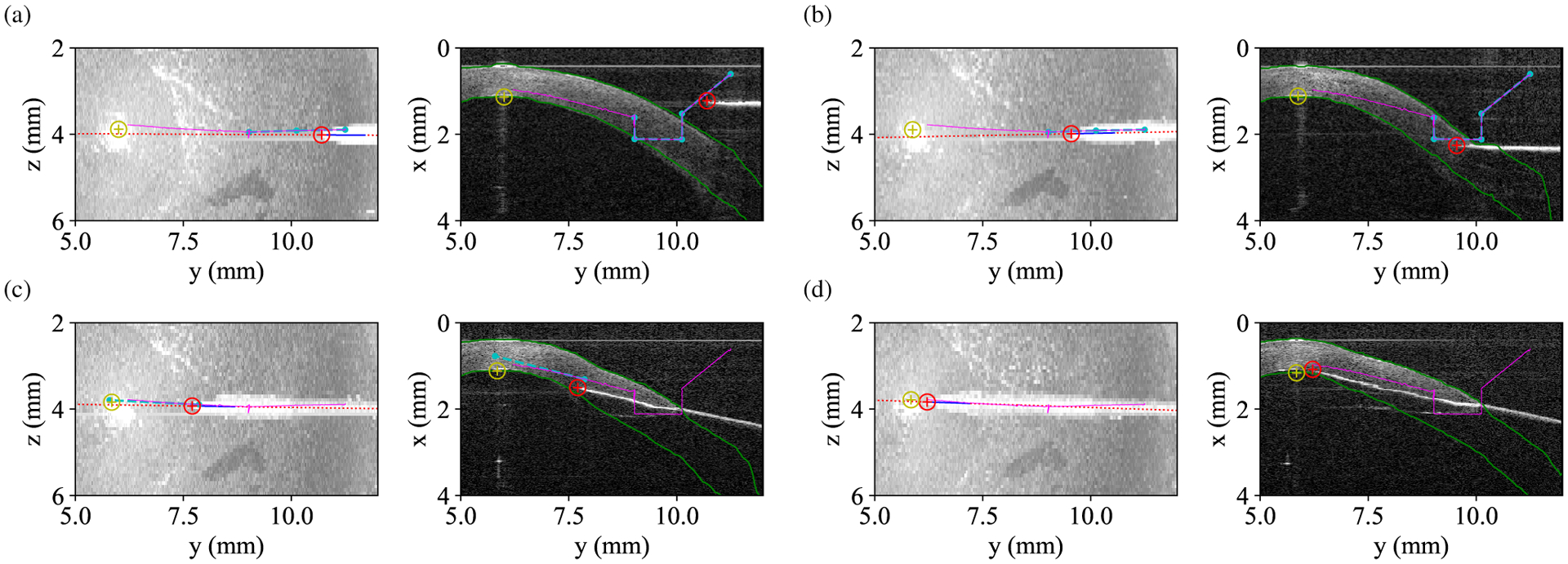
OCT maximum intensity projections (left) and index-corrected B-scans (right) illustrating path planning and execution outside the cornea (a), during embedding (b), during advancement (c), and at completion (d). Red and yellow circles denote the tracked needle and target positions, respectively. Green lines indicated corneal boundary segmentation. Cyan and purple lines show planned and executed paths from forward kinematics, respectively. The needle tip deviates from the planned trajectory due to a combination of calibration error and interactions with the cornea for which replanning compensates.
We replaced the needle and recalibrated according to Section II-F after every 2 corneas of needle insertions. We discarded trials in which the needle shaft contacted the artificial anterior chamber (AAC) because such an occurrence was an artifact of our experimental setup. In addition, we recalibrated after each AAC strike. We recorded OCT continuous volumes and robot telemetry during each insertion for later analysis.
D. Data Analysis
For each insertion (human and automatic), a single grader blinded to the experimental configuration assessed perforation, insertion time, and final needle depth using recorded OCT data. We defined corneal perforation as visualization of the needle tip posterior to the endothelium without any corneal stroma visible ahead of the needle. We estimated the insertion time by multiplying the volume period from Section II-B by the number of volumes between insertion start and end, as determined by the grader. The grader marked the start volume as the last volume in which the needle touched the corneal surface before entering the stroma. Similarly, the grader marked the final volume as the last volume in which the operator or robot advanced the needle into the cornea.
Using custom analysis software, the grader measured the final needle depth in the insertion end volume. First, the grader manually corrected any errors in automatic epithelial segmentation from Section II-C. Next, they identified the B-scan containing the needle tip and marked its location. The software then used the epithelial segmentation to correct the needle tip position for the cornea’s index of refraction and identified the epithelial position where the surface normal passed through the needle tip. This line was then warped and drawn on the raw B-scan for the grader’s reference. For index correction, we assumed a refractive index of 1.376 for all corneas by averaging known values for the anterior and posterior stroma [47]. Finally, the grader marked the position where the surface normal line crossed the endothelium, which the software again index corrected. With these annotations, we computed the remaining stromal thickness as
| (7) |
and the final depth percent as
| (8) |
E. Statistical Methods
We assessed for differences in perforation rate using Fisher’s exact test. We assessed for differences in mean depth percent, residual stroma, and insertion time using ANOVA with the post-hoc Tukey-Kramer test. We used a Type I error threshold of p = 0.05 for statistical significance.
F. Pneumodissection Proof-of-Concept
The primary experiments described above assessed needle insertion only, and thus allowed for reuse of ex vivo human corneas to maximize sample counts. In a separate proof-of-concept experiment, we attempted pneumodissection after a small number of separate automatic needle insertions to demonstrate that successful bubble formation could be achieved. For this experiment, we permitted the operator to pause the automatic insertion, by releasing the activation switch, and inject air at their discretion, which is an intended usage of hold-to-run control. We also replaced the pressurizing water column with a syringe to better simulate the anterior chamber compliance observed during in vivo pneumodissection.
IV. Results
The three corneal fellows each performed 40 needle insertions spread across 5 corneas for a total of 120 trials. These corneas had central corneal thickness range of 0.54–0.98mm with mean 0.72mm as measured by OCT immediately before each insertion. No corneas had central clouding that significantly reduced their transparency. None of the fellows reported insufficient microscope resolution for DALK cannulations. We excluded the initial 8 training insertions for each operator (Section III-B) and all 8 trials from one cornea due to a loss of AAC pressurization. In total, we obtained 22 trials for each human trial configuration (i.e., FM, FO, CM, CO). Each fellow had 1–2 yrs corneal surgery experience. Similarly, the robot arm performed 42 needle insertions spread across 7 corneas. We excluded 8 trials for the cubic planner due to AAC strikes (Section III-C). In total, we obtained 21 trials for the line planner and 13 trials for the cubic planner. Fig. 10 plots the final needle depth, residual stroma, and insertion time by configuration for all included insertions that did not exhibit perforation. Note that residual stroma measurements are not directly comparable to in vivo ones due to age-dependent swelling of the ex vivo corneas. Fig. 11 demonstrates a successful pneumodissection performed after an automatic needle insertion with the line planner.
Fig. 10.
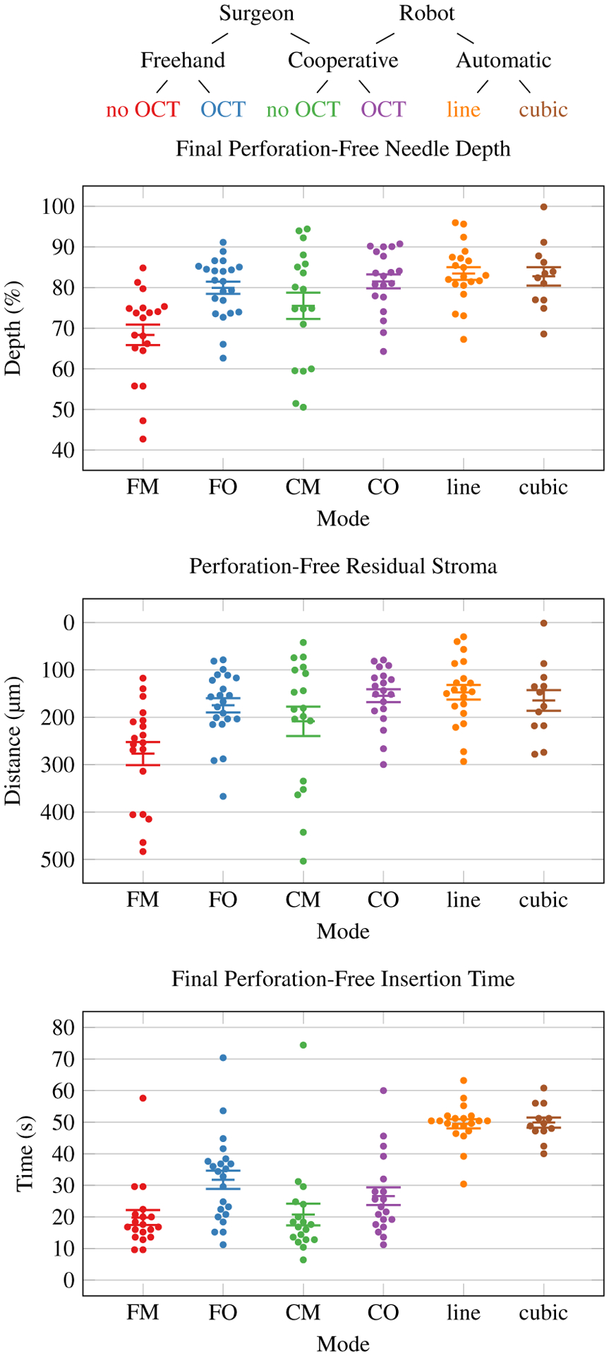
Final perforation-free needle depth, residual stromal, and insertion time by mode with configuration code key. Improved needle insertion performance is higher depth percentage and less residual stroma. Each dot represents one perforation-free trial. Error bars indicate standard error of the mean.
Fig. 11.
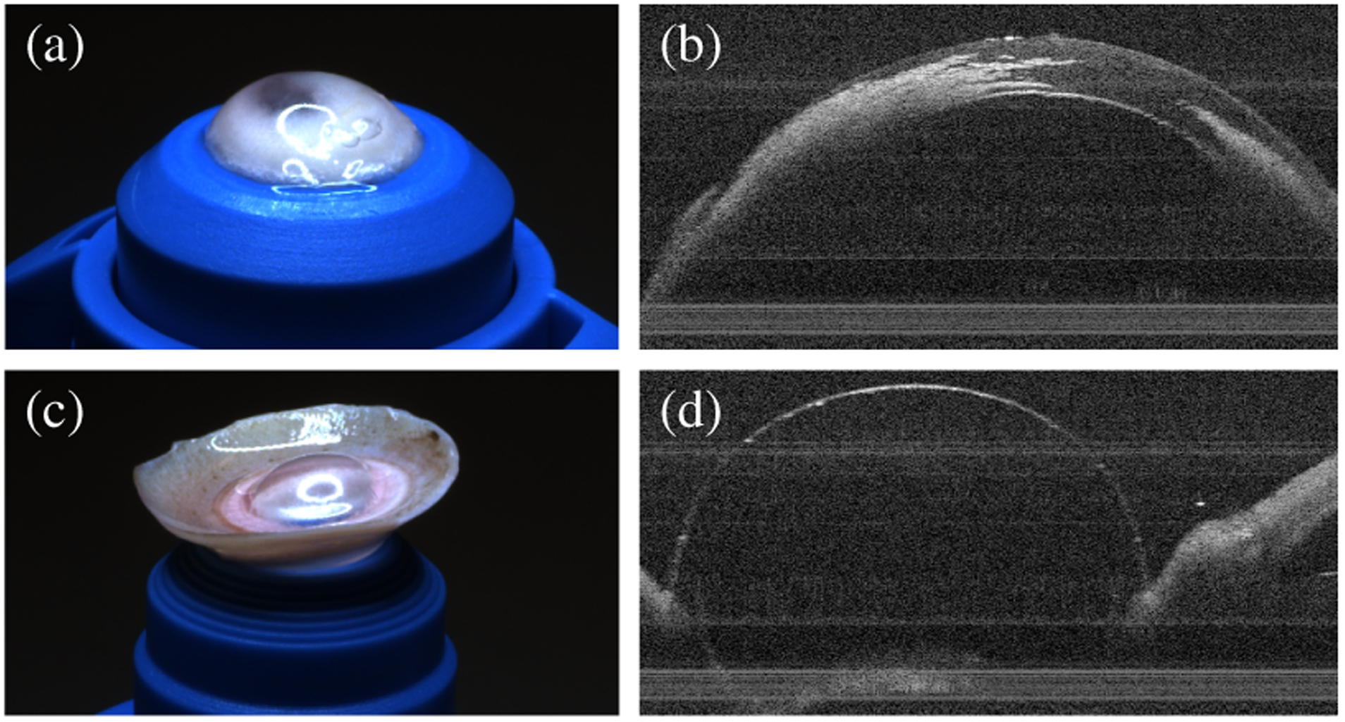
Successful pneumodissection on gross and OCT examination after automatic needle insertion, showing intrastromal air after injection (a–b) and inversion of the cornea to confirm bubble formation (c–d).
Table I lists the perforation, residual stroma, needle depth, and insertion time summary statistics for these insertions. Fisher’s exact test for the perforation rate yielded no statistically significant difference between configurations (p = 0.33). An analysis of variance (ANOVA) of final depth and residual stroma for perforation-free trials yielded significant variation between configurations (F(5,104) = 6.62, p < 0.001 and F(5,104) = 5.34, p < 0.001, respectively). The post-hoc Tukey-Kramer test revealed statistically significant final depth and residual stroma differences between the freehand microscope-only (FM) configuration and all OCT-guided or automatic configurations (FO, CO, line, and cubic). All other perforation-free final depth and residual stroma differences were not statistically significant.
TABLE I.
Summary of needle insertion results
| Perforation | Final Depth | Residual Stroma* | Insertion Time | |||||||
|---|---|---|---|---|---|---|---|---|---|---|
| Cfg. | N | n | % | μ | σ | μ | σ | μ | σ | |
| Baseline | FM | 22 | 3 | 13.6% | 68.4 ± 2.5% | 10.9% | 277 ± 24 μm | 106 μm | 19.8 ± 2.4 s | 10.4 s |
| Manual | FO | 22 | 0 | 0.0% | 80.0 ± 1.5% | 7.1% | 175 ± 15 μm | 71 μm | 31.8 ± 2.9 s | 13.5 s |
| CM | 22 | 4 | 18.2% | 75.5 ± 3.2% | 13.8% | 209 ± 31 μm | 132 μm | 20.8 ± 3.4 s | 14.5 s | |
| CO | 22 | 3 | 13.6% | 81.5 ± 1.7% | 7.4% | 155 ± 14 μm | 60 μm | 26.6 ± 2.8 s | 12.2 s | |
| Automatic | line | 21 | 1 | 4.8% | 83.4 ± 1.6% | 7.0% | 147 ± 15 μm | 68 μm | 49.5 ± 1.4 s | 6.4 s |
| cubic | 13 | 1 | 7.7% | 82.8 ± 2.3% | 7.8% | 165 ± 22 μm | 76 μm | 49.9 ± 1.6 s | 5.6 s | |
Measurements not directly comparable to in vivo results due to swelling that may occur during tissue preservation.
An ANOVA of insertion time for perforation-free trials yielded significant variation between configurations (F(5,104) = 23.50, p < 0.001). The post-hoc Tukey-Kramer test revealed many statistically significant insertion time differences. Notably, the increase in time from FM to FO was significant, but FM, CM, and CO were mutually not significantly different. CO and FO were also not significantly different. All automatic configurations required statistically significantly more time that all manual configurations.
V. Discussion
We have demonstrated a DALK technique that improves human performance in cornea cannulation in an ex vivo model by providing OCT for visualization and a cooperative robot for enhanced needle control. Between the visualization (FO) and manipulation (CM) interventions, providing OCT guidance (FO) produced the largest improvement in needle depth and eliminated perforations. Freehand OCT-guided needle insertions exhibited a 61% increase in time requirements, however. Although the need for an additional 10 s is likely unimportant for a task performed once during DALK, it is clear that the additional visual feedback slowed the cornea fellows. We in part attribute the increased duration to the low 0.8 Hz update rate for our OCT system. We also suspect that giving fellows visual feedback on their needle depth encouraged them to spend additional effort in reaching the target.
Introducing a cooperative robot arm along with OCT-guidance (CO), however, increased the insertion time by only 38%. Possible explanations for shorter times include increased confidence with the robot, reduced effort required to advance the needle, or distraction from the OCT visualization. Regardless of the underlying reason, cooperative robot use did not affect the perforation rate (FM vs. CM) and eliminated the reduction in perforations seen with OCT-guidance (FO vs. CO). Nevertheless, using a cooperative robot with OCT did significantly increase the final depth (FM vs. CO), but if a surgeon had to choose between OCT and a cooperative robot, improved visualization with OCT is the better choice for now. The primary benefits, then, of the cooperative approach are its regulation of the advancement rate and maintenance of needle position, which allow the surgeon to focus on depth and pause for evaluation, respectively. Our data show that the robot provides these features without negatively impacting needle insertion performance.
Of note, this study reproduced our previously reported results [15] when considering the FM and FO configurations. In our prior analog to FO, we reported a meand ± standard deviation depth of 78.6±6.7 % which agrees with our result here of 80.0±7.1 %. The perforations rates of 6.7% and 0% are similar as well. Our current cornea fellows performed significantly better than the prior ones in the FM configuration, however. Compared to the prior 61.4±17.2 depth and 50% perforation rate, we observed 68.4±10.9% depth and 13.6% perforation rate. The much lower perforation rate is particularly pronounced and prevented us from showing a statistically significant reduction in perforation rate with OCT guidance or the cooperative robot.
We have also demonstrated automatic OCT-guided needle insertions for DALK that meet or exceed surgeon performance. By reliably automating cornea cannulation, the major challenge in “big bubble” DALK, we can potentially not only improve the procedure’s success but also enable surgeons who struggle with this step. All advancement planners exhibited one or fewer perforations with final depths slightly deeper, although not statistically significantly so, than the best manual performance we observed (FO and CO). This is particularly interesting because the line planner uses perhaps the most primitive approach to DALK needle insertions: aim at the apex and advance in a straight line. While somewhat unsurprising given the short spatial scale of these needle insertions (~ 4mm), the result is notable. These data suggest that when learning DALK, cornea fellows can readily achieve high performance without complex needle paths; a straight-line path is sufficient. Additionally, the automatic planners’ increased insertion time is not particularly meaningful because faster OCT engines will allow us to increase the insertion velocity without sacrificing accuracy.
Many of the cubic planner’s samples were discarded due to AAC contact, however. This frequent AAC contact is due to the steeper slope that the cubic planner used when following the cornea’s natural curvature. In contrast, the line planner maintained a more level slope, thereby minimizing AAC contact. This same issue appears in in vivo DALK as access to the eye is mechanically restricted by the surrounding orbit. Corneal surgeons have almost certainly already discovered that steep needle orientations lead to such problems.
As mentioned in Section II-E, skipping trephination before cannulating the cornea in “big bubble” DALK simplified our automatic approach. By similarly skipping trephination during manual DALK, we facilitated fair comparison to automatic DALK and our prior results [15]. Although manual DALK without trephination is feasible [3]–[7], its associated needle tracts are significantly longer, which produces several effects. First, the corneal stroma tethers the needle shaft at the insertion site, which restricts tip translation. The tip is instead maneuvered by applying pressure in the intended direction of travel while advancing the needle. Second, although the longer tract increases the opportunity for error during insertion, it yields a more gradual and controlled approach of the endothelium. The latter promotes monitoring and feedback from OCT by slowing the rate of descent. These two effects do alter the needle insertion mechanics, but we believe they do not prevent generalization to DALK with trephination.
Finally, we must note that final needle depth is only a proxy for the desired outcome in DALK: successful pneumodissection. That said, final needle depth is strongly correlated with pneumodissection success both in ex vivo models like ours [8] and in vivo surgery [10]. Eventually, we will need to demonstrate reliable pneumodissections using our cooperative and automatic approaches, however. The data presented here involved 162 needle insertions and 22 cadaveric corneas. Performing a pneumodissection after each trial would have required 162 corneas, a human tissue scale which was not practical for this work. Unfortunately, neither rabbit [51] nor porcine [52] corneas serve as acceptable substitutes for human tissue. For now, we believe that the successful bubble formation in Fig. 11 is encouraging to motivate future larger-scale pneumodissection studies.
Looking forward, we envision the DALK workstation as a mobile cart bearing the manipulation subsystem (i.e., the robot arm) and control hardware. Although we provided our own visualization subsystem here, we anticipate interfacing with commercially-available intraoperative OCT systems that support access to live OCT volumes. In our scheme, the cart is brought to the operating table only once the surgeon is ready to cannulate the cornea. For a cooperative insertion, the surgeon simply extends the arm and proceeds with the needle insertion. For an automatic insertion, the surgeon uses cooperative mode to position the needle tip within the OCT field of view and runs the automated calibration procedure. The workstation is then ready for an automatic needle insertion. Should the cart or microscope require adjustment, the calibration is quickly repeated. Once the needle is placed and air injected, the surgeon retracts the robot arm under cooperative control, and the cart is removed so that the DALK procedure may continue as normal.
Presently, the primary barrier to clinically deploying the DALK workstation is safety. In particular, unexpected robot movements pose a danger to the patient, surgeon, and operating room staff, whether the robot is in cooperative or automatic mode. This risk is best mitigated by using robots that incorporate dedicated safety computers for regulating the robot’s motion, even during hardware failures. Further risk reduction can be achieved by instrumenting the robot arm with sensors that allow it to detect contact with the environment. An alternative approach is building the workstation with a robot arm that is intrinsically safe due to its design or hardware limitations. Our control software is robot-independent and only requires a robot with sufficiently high control bandwidth to support impedance control with acceptably low stiffnesses.
VI. Conclusion
DALK poses significant challenges for surgeons in terms of depth visualization and precise needle control that limit its clinical success. We address these challenges with volumetric OCT for visualization and a robot arm for cooperative or automatic needle control and examine the effectiveness of these interventions in an established ex vivo cadaver cornea model. Our results demonstrate that live OCT is a key enabler of manual needle insertions in DALK by both promoting depth and suppressing perforation. Guided by OCT with cornea segmentation and tool tracking, however, automatic needle insertions can meet or exceed the performance of cornea fellows. This effect persists even with OCT and robotic needle stabilization to support the fellows. Furthermore, robotic experiments show that a straight-line path to the apex after needle embedding is sufficient to achieve reliable success. This has ramifications for how surgeons train to perform this procedure. We believe these advances will improve the success of DALK and thereby spare eligible patients the post-transplant morbidity associated with full thickness grafts.
Acknowledgment
The authors would like to thank the Miracles In Sight eye bank for donating research-grade corneas, Yuan Tian for his assistance in conducting the manual trials, and the Duke Eye Center cornea fellows for their participation.
This research is partially supported by NIH F30-EY027280, NIH T32-GM007171, partial support from NIH R21 EY029877, and the Coulter Translational Partnership.
Contributor Information
Mark Draelos, Department of Biomedical Engineering, Duke University, Durham, NC, USA..
Gao Tang, Department of Mechanical Engineering and Materials Science, Duke University, Durham, NC, USA..
Brenton Keller, Department of Biomedical Engineering, Duke University, Durham, NC, USA..
Anthony Kuo, Department of Ophthalmology, Duke University Medical Center, Durham, NC, USA..
Kris Hauser, Department of Electrical and Computer Engineering, Duke University, Durham, NC, USA..
Joseph A. Izatt, Department of Biomedical Engineering, Duke University, Durham, NC, USA.
References
- [1].Dunn SP et al. , “Corneal graft rejection 10 years after penetrating keratoplasty in the cornea donor study,” Cornea, vol. 33, no. 10, pp. 1003–9, 2014. [DOI] [PMC free article] [PubMed] [Google Scholar]
- [2].Anwar M and Teichmann KD, “Big-bubble technique to bare Descemet’s membrane in anterior lamellar keratoplasty,” Journal of Cataract & Refract Surgery, vol. 28, no. 3, pp. 398–403, 2002. [DOI] [PubMed] [Google Scholar]
- [3].Archila EA, “Deep lamellar keratoplasty dissection of host tissue with intrastromal air injection,” Cornea, vol. 3, no. 3, pp. 217–218, 1984. [PubMed] [Google Scholar]
- [4].Morris E et al. , “Corneal endothelial specular microscopy following deep lamellar keratoplasty with lyophilised tissue,” Eye, vol. 12, no. 4, p. 619, 1998. [DOI] [PubMed] [Google Scholar]
- [5].Melles GR et al. , “A quick surgical technique for deep, anterior lamellar keratoplasty using visco-dissection,” Cornea, vol. 19, no. 4, pp. 427–432, 2000. [DOI] [PubMed] [Google Scholar]
- [6].Coombes AGA, Kirwan JF, and Rostron CK, “Deep lamellar keratoplasty with lyophilised tissue in the management of keratoconus,” British Journal of Ophthalmology, vol. 85, no. 7, pp. 788–791, 2001. [DOI] [PMC free article] [PubMed] [Google Scholar]
- [7].Reinhart WJ et al. , “Deep anterior lamellar keratoplasty as an alternative to penetrating keratoplasty: a report by the American Academy of Ophthalmology,” Ophthalmology, vol. 118, no. 1, pp. 209–218, 2011. [DOI] [PubMed] [Google Scholar]
- [8].Pasricha ND et al. , “Needle depth and big bubble success in deep anterior lamellar keratoplasty: An ex vivo microscope-integrated OCT study,” Cornea, vol. 35, no. 11, p. 1471, 2016. [DOI] [PMC free article] [PubMed] [Google Scholar]
- [9].Borderie VM et al. , “Long-term results of deep anterior lamellar versus penetrating keratoplasty,” Ophthalmology, vol. 119, no. 2, pp. 249–55, 2012. [DOI] [PubMed] [Google Scholar]
- [10].Busin M et al. , “Outcomes of air injection within 2mm inside a deep trephination for deep anterior lamellar keratoplasty in eyes with keratoconus,” American Journal of Ophthalmology, vol. 164, no. Supplement C, pp. 6–13, 2016. [DOI] [PubMed] [Google Scholar]
- [11].Tao YK et al. , “Image-guided modified deep anterior lamellar keratoplasty (DALK) corneal transplant using intraoperative optical coherence tomography,” in Ophthalmic Technologies XXV in SPIE BiOS, vol. 9307, 2015. [Google Scholar]
- [12].Steven P et al. , “Optimising deep anterior lamellar keratoplasty (DALK) using intraoperative online optical coherence tomography (iOCT),” British Journal of Ophthalmology, vol. 98, no. 7, pp. 900–904, 2014. [DOI] [PMC free article] [PubMed] [Google Scholar]
- [13].Benito-Llopis LD et al. , “Intraoperative anterior segment optical coherence tomography: A novel assessment tool during deep anterior lamellar keratoplasty,” American Journal of Ophthalmology, vol. 157, no. 2, pp. 334 – 341.e3, 2014. [DOI] [PubMed] [Google Scholar]
- [14].Scorcia V et al. , “Anterior segment optical coherence tomography-guided big-bubble technique,” Ophthalmology, vol. 120, no. 3, pp. 471 – 476, 2013. [DOI] [PubMed] [Google Scholar]
- [15].Keller B et al. , “Real-time corneal segmentation and 3D needle tracking in intrasurgical OCT,” Biomedical Optics Express, vol. 9, no. 6, pp. 2716–2732, June 2018. [DOI] [PMC free article] [PubMed] [Google Scholar]
- [16].Han J-H et al. , “Common-path fourier-domain optical coherence tomography with a fiber optic probe integrated into a surgical needle,” in Conference on Lasers and Electro-Optics/International Quantum Electronics Conference. Optical Society of America, 2009, p. CMCC2. [Google Scholar]
- [17].Shin S et al. , “Lamellar keratoplasty using position-guided surgical needle and m-mode optical coherence tomography,” Journal of Biomedical Optics, vol. 22, no. 12, pp. 1 – 7, 2017. [DOI] [PubMed] [Google Scholar]
- [18].Choma MA et al. , “Sensitivity advantage of swept source and fourier domain optical coherence tomography,” Optics Express, vol. 11, no. 18, pp. 2183–2189, September 2003. [DOI] [PubMed] [Google Scholar]
- [19].Oh W-Y et al. , “115 kHz tuning repetition rate ultrahigh-speed wavelength-swept semiconductor laser,” Optics Letters, vol. 30, no. 23, pp. 3159–3161, December 2005. [DOI] [PMC free article] [PubMed] [Google Scholar]
- [20].Oh W-Y et al. , “>400 kHz repetition rate wavelength-swept laser and application to high-speed optical frequency domain imaging,” Optics Letters, vol. 35, no. 17, pp. 2919–2921, September 2010. [DOI] [PMC free article] [PubMed] [Google Scholar]
- [21].Jian Y, Wong K, and Sarunic MV, “Graphics processing unit accelerated optical coherence tomography processing at megahertz axial scan rate and high resolution video rate volumetric rendering,” Journal of Biomedical Optics, vol. 18, pp. 18– 18–5, 2013. [DOI] [PubMed] [Google Scholar]
- [22].Shieh C et al. , “Impact of microscope integrated OCT on ophthalmology resident performance of anterior segment maneuvers in model eyes,” Investigative Ophthalmology & Visual Science, vol. 56, no. 7, p. 4086, 2015. [DOI] [PMC free article] [PubMed] [Google Scholar]
- [23].Pasricha ND et al. , “Real-time microscope-integrated OCT to improve visualization in DSAEK for advanced bullous keratopathy,” Cornea, vol. 34, no. 12, pp. 1606–1610, 2015. [DOI] [PMC free article] [PubMed] [Google Scholar]
- [24].Toth CA et al. , “Surgically integrated swept source optical coherence tomography (SSOCT) to guide vitreoretinal (VR) surgery,” Investigative Ophthalmology & Visual Science, vol. 56, no. 7, p. 3512, 2015. [Google Scholar]
- [25].Carrasco-Zevallos OM et al. , “Live volumetric (4D) visualization and guidance of in vivo human ophthalmic surgery with intraoperative optical coherence tomography,” Scientific Reports, vol. 6, p. 31689, 2016. [DOI] [PMC free article] [PubMed] [Google Scholar]
- [26].Carrasco-Zevallos OM et al. , “Review of intraoperative optical coherence tomography: technology and applications,” Biomedical Optics Express, vol. 8, no. 3, pp. 1607–1637, 2017. [DOI] [PMC free article] [PubMed] [Google Scholar]
- [27].Safwat B et al. , “The role of posture, magnification, and grip force on microscopic accuracy,” Annals of Biomedical Engineering, vol. 37, no. 5, pp. 997–1006, May 2009. [DOI] [PubMed] [Google Scholar]
- [28].Riviere CN and Khosla PK, “Accuracy in positioning of handheld instruments,” in Annual International Conference of the IEEE EMBS Society, vol. 1, October 1996, pp. 212–213. [Google Scholar]
- [29].Hotraphinyo LF and Riviere CN, “Three-dimensional accuracy assessment of eye surgeons,” in Annual International Conference of the IEEE EMBS Society, vol. 4, October 2001, pp. 3458–3461. [Google Scholar]
- [30].Gupta PK, Jensen PS, and de Juan E, “Surgical forces and tactile perception during retinal microsurgery,” in Medical Image Computing and Computer-Assisted Intervention, Taylor C and Colchester A, Eds. Berlin, Heidelberg: Springer Berlin Heidelberg, 1999, pp. 1218–1225. [Google Scholar]
- [31].MacLachlan RA et al. , “Micron: An actively stabilized handheld tool for microsurgery,” IEEE Transactions on Robotics, vol. 28, no. 1, pp. 195–212, 2012. [DOI] [PMC free article] [PubMed] [Google Scholar]
- [32].Cheon GW et al. , “Motorized microforceps with active motion guidance based on common-path SSOCT for epiretinal membranectomy,” IEEE/ASME Transactions on Mechatronics, vol. 22, no. 6, pp. 2440–2448, December 2017. [DOI] [PMC free article] [PubMed] [Google Scholar]
- [33].Taylor R et al. , “A steady-hand robotic system for microsurgical augmentation,” The International Journal of Robotics Research, vol. 18, no. 12, pp. 1201–1210, 1999. [Google Scholar]
- [34].Üneri A et al. , “New steady-hand eye robot with micro-force sensing for vitreoretinal surgery,” in IEEE RAS/EMBS International Conference on Biomedical Robotics and Biomechatronics, September 2010, pp. 814–819. [DOI] [PMC free article] [PubMed] [Google Scholar]
- [35].Gijbels A et al. , “Design and realisation of a novel robotic manipulator for retinal surgery,” in IEEE/RSJ International Conference on Intelligent Robots and Systems, November 2013, pp. 3598–3603. [Google Scholar]
- [36].Meenink H, “Vitreo-retinal eye surgery robot: Sustainable precision,” Ph.D. dissertation, Eindhoven University of Technology, 2011. [Google Scholar]
- [37].Rahimy E et al. , “Robot-assisted intraocular surgery: Development of the IRISS and feasibility studies in an animal model,” Eye, vol. 27, no. 8, p. 972, 2013. [DOI] [PMC free article] [PubMed] [Google Scholar]
- [38].Yu H et al. , “Evaluation of microsurgical tasks with OCT-guided and/or robot-assisted ophthalmic forceps,” Biomedical Optics Express, vol. 6, no. 2, pp. 457–472, February 2015. [DOI] [PMC free article] [PubMed] [Google Scholar]
- [39].Edwards T et al. , “First-in-human study of the safety and viability of intraocular robotic surgery,” Nature Biomedical Engineering, vol. 2, no. 9, p. 649, 2018. [DOI] [PMC free article] [PubMed] [Google Scholar]
- [40].Gijbels A et al. , “In-human robot-assisted retinal vein cannulation, a world first,” Annals of Biomedical Engineering, vol. 46, no. 10, pp. 1676–1685, October 2018. [DOI] [PubMed] [Google Scholar]
- [41].Chen C-W et al. , “Intraocular robotic interventional surgical system (IRISS): Semi-automated OCT-guided cataract removal,” The International Journal of Medical Robotics and Computer Assisted Surgery, vol. 14, no. 6, p. e1949, 2018. [DOI] [PubMed] [Google Scholar]
- [42].Draelos M et al. , “Real-time image-guided cooperative robotic assist device for deep anterior lamellar keratoplasty,” in EEE International Conference on Robotics and Automation (ICRA), May 2018, pp. 1–9. [Google Scholar]
- [43].Bhullar PK et al. , “Intraocular pressure and big bubble diameter in deep anterior lamellar keratoplasty: An ex-vivo microscope-integrated OCT with heads-up display study,” Asia-Pacific Journal of Ophthalmology, vol. 6, no. 5, pp. 412–417, 2017. [DOI] [PMC free article] [PubMed] [Google Scholar]
- [44].LaRocca F et al. , “Robust automatic segmentation of corneal layer boundaries in SDOCT images using graph theory and dynamic programming,” Biomedical Optics Express, vol. 2, no. 6, pp. 1524–1538, 2011. [DOI] [PMC free article] [PubMed] [Google Scholar]
- [45].Chiu SJ et al. , “Automatic segmentation of closed-contour features in ophthalmic images using graph theory and dynamic programming,” Biomedical Optics Express, vol. 3, no. 5, pp. 1127–1140, 2012. [DOI] [PMC free article] [PubMed] [Google Scholar]
- [46].Zhao M, Kuo AN, and Izatt JA, “3D refraction correction and extraction of clinical parameters from spectral domain optical coherence tomography of the cornea,” Optics Express, vol. 18, no. 9, pp. 8923–8936, April 2010. [DOI] [PubMed] [Google Scholar]
- [47].Patel S, Marshall J, and Fitzke FW I.I.I., “Refractive index of the human corneal epithelium and stroma,” Journal of Refractive Surgery, vol. 11, no. 2, pp. 100–105, March 1995. [DOI] [PubMed] [Google Scholar]
- [48].Besl PJ, McKay ND et al. , “A method for registration of 3-D shapes,” IEEE Transactions on Pattern Analysis and Machine Intelligence, vol. 14, no. 2, pp. 239–256, 1992. [Google Scholar]
- [49].Bertalmio M, Bertozzi AL, and Sapiro G, “Navier-stokes, fluid dynamics, and image and video inpainting,” in IEEE Computer Society Conference on Computer Vision and Pattern Recognition (CVPR), vol. 1, 2001, pp. I–355–I–362. [Google Scholar]
- [50].Draelos M et al. , “Automating needle insertions for deep anterior lamellar keratoplasty,” in Open Challenges and State-of-the-Art in Control System Design and Technology Development for Surgical Robotic Systems Workshop at IEEE International Conference on Robotics and Automation (ICRA), May 2019. [Google Scholar]
- [51].Jue B and Maurice DM, “The mechanical properties of the rabbit and human cornea,” Journal of Biomechanics, vol. 19, no. 10, pp. 847 – 853, 1986. [DOI] [PubMed] [Google Scholar]
- [52].Elsheikh A, Alhasso D, and Rama P, “Biomechanical properties of human and porcine corneas,” Experimental Eye Research, vol. 86, no. 5, pp. 783 – 790, 2008. [DOI] [PubMed] [Google Scholar]