

Abstract

Metal–organic frameworks (MOFs) are appealing heterogeneous support matrices that can stabilize molecular catalysts for the electrochemical conversion of small molecules. However, moving from a homogeneous environment to a porous film necessitates the transport of both charge and substrate to the catalytic sites in an efficient manner. This presents a significant challenge in the application of such materials at scale, since these two transport phenomena (charge and mass transport) would need to operate faster than the intrinsic catalytic rate in order for the system to function efficiently. Thus, understanding the fundamental kinetics of MOF-based molecular catalysis of electrochemical reactions is of crucial importance. In this Perspective, we quantitatively dissect the interplay between the two transport phenomena and the catalytic reaction rate by applying models from closely related fields to MOF-based catalysis. The identification of the limiting process provides opportunities for optimization that are uniquely suited to MOFs due to their tunable molecular structure. This will help guide the rational design of efficient and high-performing catalytic MOF films with incorporated molecular catalyst for electrochemical energy conversion.
Introduction
Metal–organic frameworks (MOFs) are emerging as widely popular support structures to incorporate molecular catalysts for the electrochemical activation and conversion of small molecules.1−3 Composed of discrete molecular building blocks (organic linkers and metal nodes),4,5 MOFs have a wide range of synthetic tunability.6,7 Varying the microscopic molecular structure produces materials with different pore sizes and chemical environments, perhaps allowing for augmentation of the active site of molecular catalysts.8 In addition, the permanent porosity and high internal surface area of many MOFs could result in very high active-site densities,9 which is necessary for the fast transformation of substrate into product per unit volume.10
However, when moving away from a homogeneous environment to heterogeneous porous films, chemical reactions become interfacial in nature as a consequence of immobilizing or heterogenizing the molecular catalyst into a three-dimensional support matrix. For the system to operate efficiently in such cases, both charge and substrate must be transported to the catalytic sites within the film at a faster rate than the intrinsic turnover rate of the catalytic reaction. We postulate in this Perspective that one critical, but often overlooked, aspect of utilizing MOFs for the molecular catalysis of electrochemical reactions is transport.
In MOF films with discrete redox-active molecular linkers, electron-hopping—formally governed by Fick’s laws of diffusion—delivers charge to the catalytic sites. Therefore, the diffusional transport of both charge and substrate needs to be appropriately accounted for in order to quantitatively characterize and optimize each potentially limiting process. Diffusion has the potential to be much slower compared to other processes occurring during catalysis, particularly chemical reaction rates, and this can be exacerbated in the confined environments of porous materials. Given the microporous nature of MOFs, transport phenomena are expected (and in a few exceptional cases have been qualitatively shown, as will be discussed) to have an enormous effect on the overall catalytic performance of electroactive MOF films. The observed reaction rate easily can be limited by mass or charge transport if these phenomena are not controlled or optimized. While experimentally examining MOF-based reactions, it is imperative to remember that when these reactions are coupled with diffusion,11,12 substrates and/or catalytic intermediates will have spatially dependent concentration profiles, and their concentration throughout the film may not reflect the bulk concentrations of these species.
In the following sections, we will explore well-established electrochemical methods to quantify rates of charge transport, substrate diffusion, and the intrinsic catalytic reaction. Next, the question, “Where is the bottleneck for catalysis?” is posed and answered by examining each potentially limiting transport process in detail with numerical simulations, incorporating relevant data from the literature. Concepts of charge transport dynamics and catalytic reaction engineering from closely related fields are utilized to understand these issues on a fundamental level. Finally, looking to the future, the quantitative analysis and parameters detailed in the beginning sections are used to understand how to optimize catalytic performance and design new MOFs, which alleviate transport limitations. The reaction-diffusion kinetic models outlined here reveal important design rules, and indicate which features of the catalyst–support system to select and optimize in order to rationally control transport and ultimately reactivity. While the incorporation of transport phenomena into kinetic studies of MOF-based catalysis is under-represented in the literature, it is certainly not unique to MOFs. Many of the concepts of reaction-diffusion kinetics that will be discussed here apply widely to other micro- or mesoporous catalyst materials.10,13−15 However, MOFs do offer a unique opportunity for rational control over mass and charge transport properties at the molecular level. This is enabled by the vast array of combinations for both the organic linkers and the connectivity between these building blocks via the inorganic nodes, as well as the synthetic tuning possible for both these functionalities. More research is certainly needed to translate molecular-level design of MOFs into targeted control over macroscopic transport properties, which is crucial to optimize catalysis for large-scale applications. However, the first step toward this goal, and consequently the focus of the following discussion, is to delineate and quantitatively characterize the influence of transport phenomena on chemical reactivity in MOFs by simple kinetic models, leading to specific design criteria for not only transport properties but also for important extrinsic parameters such as film thickness. This has implications for MOFs applied to the electrochemical conversion of small molecules for energy related processes (fuel-forming reactions, water oxidation etc.), but also potentially to recently revitalized electrochemical organic transformations and redox catalysis producing high-value organic products.16−18 We end by summarizing the opportunities and challenges for MOFs entering applications as high-performance catalytic films for this variety of possible electrochemical reactions.
Revisiting Reaction-Diffusion
The analysis of transport phenomena occurring in porous media and their effect on catalytic reactions has some important historical origins. The year 2019 celebrated the 80th anniversary of Prof. E. W. Thiele’s pioneering publication, “Relationship between Catalytic Activity and Size of Particle”.19 Therein, Thiele presented a model for reaction-diffusion occurring in porous catalyst particles or “grains” and outlined two regimes: (1) where the intrinsic kinetics of the catalyst solely limit the overall reaction rate, and (2) where internal substrate diffusion limits the overall reaction rate. An important part of these results accounts for the transition between these two scenarios in a quantitative manner and predicts the resulting behavior based on a small number of input parameters. This is accomplished by defining a single descriptor, a dimensionless control parameter that has come to be known as the Thiele modulus ϕ,
| 1 |
where Ra is the radius of the equivalent sphere, kcat is the first-order rate constant of the catalytic reaction, and DS is the diffusion coefficient of the substrate inside the particle. This very simply states that the efficiency of any chemical reaction occurring in concert with diffusion will be a function of a geometric length scale describing the physical system, the catalytic rate, and the diffusivity of the substrate. If the time scale required for substrate to diffuse through the particle is large compared to the reaction rate (ϕ > 1), the substrate will be consumed by the reaction before permeating through the entire particle. A boundary layer (also referred to as a reaction-diffusion layer) forms near the particle surface, which limits the amount of catalyst actively participating in the reaction—in other words, the catalysts in the interior of the particle are largely dormant (Figure 1). Thus, porous catalysts with large particle sizes and/or very fast reactions will have a significant diffusional resistance that lowers the observed reaction rate.13,20,21 Therefore, an optimized catalytic material will inevitably have these parameters balanced appropriately, so that any limitations of transport by diffusion on the reaction rate are small or negligible. Thiele developed his model for catalyst particles of several different geometries, but the same underlying physical principle applies here to porous MOF film electrodes. In either case, overall efficiency is controlled by the ratio of the intrinsic catalytic reaction rate to a particular diffusion rate (this could be the diffusion of either charge or substrate through the MOF film). Efficiency, in this context, denotes how much of the catalyst is utilized during the reaction in the particle or film, i.e., the ratio of the amount of active catalyst to the total amount of catalyst contained in the MOF. This metric is canonically referred to as the “effectiveness factor” 21 and is easily quantified as the observed reaction rate divided by the maximum reaction rate in the absence of any diffusional gradients or transport limitations.13,20,21 Practitioners in MOF-based catalysis of both chemical and electrochemical reactions are encouraged to read Thiele’s original paper—its message is indeed still as timely now as it was in 1939. We will see in later sections how the same physical principles captured by Thiele’s modulus can influence catalysis of electrochemical reactions mediated by molecular species covalently incorporated in MOF film electrodes. For convenience, the dimensionless parameters used in this Perspective are summarized in Table 1. It is important to highlight the outstanding independent contribution of Dr. Gerhard Damköhler, who arrived at the same relationship between mass transport and chemical reactions.22 In his honor, the Damköhler number (Da) is often used to represent the ratio between a particular reaction rate and a convective mass transport rate.21
Figure 1.

(a) Quantitative representation of a boundary or reaction-diffusion layer in a MOF particle (approximated as spherical) for a first-order reaction at steady state. Dimensionless concentration is displayed on the y-axis, where CS is the substrate concentration inside the MOF particle (a function of the radial distance r), and CS0 is the bulk substrate concentration (taken as constant outside the particle for simplicity). The dimensionless radial coordinate (Ra is the particle radius) is plotted on the x-axis. The arrow indicates increasing values of the Thiele modulus, ϕ > 1. (b) Expanded region showing reaction-diffusion layer, with thickness given by δrxn.
Table 1. Dimensionless Parametersa.

A full list of all dimensional symbols and their definitions is given in the Symbols section.
Charge Transport Dynamics
Returning to electroactive MOF films, in this section we will introduce two primary microscopic charge transport mechanisms, band or ohmic conduction (migration) and electron-hopping conduction (formally diffusion), which carry electrons or holes to the covalently incorporated molecular catalysts. MOFs with discrete redox-active linkers (e.g., molecular metallocatalysts) most often exhibit an electron-hopping mechanism, which will be the main focus of the following discussion. Since electron hopping is formally a diffusion process (vide infra), these concepts will become important when considering the reciprocity between the rate of charge transport and catalysis and how the resulting reaction-diffusion behavior of the film can affect catalytic efficiency and kinetic measurements.
Band or ohmic conduction occurs when the electronic states of the MOF are highly delocalized and possibly strongly coupled to the electrode’s electronic states, due to through-bond or through-space conjugation of the organic linkers and/or metal nodes.23 Electron movement in the film in this case is driven by migration as a result of electrical potential gradients. Experimentally, cyclic voltammograms (CVs) of such films display only capacitive current (faradaic waves are only observed if interaction with a substrate molecule causes the injected charge to be localized at a specific site).24,25 An example of this behavior was demonstrated by a highly conjugated (electrical conductivity σ = 40 S cm–1) Ni3(hexaiminotriphenylene)2 2-D MOF reported by Dincă and co-workers for the oxygen reduction reaction (ORR).26 Under a N2 atmosphere, a large capacitive wave is observed, while conversely if O2 is added to the cell, there is a clear increase in current corresponding to the faradaic signature of the charge transfer reactions occurring during catalysis.
Alternatively, a MOF film may have components that are redox-active within a given potential window but are not electronically coupled to one another through conjugation, where the electronic states of the MOF are now spatially localized and defined by standard potentials (E0). Thus, in this instance electron hopping will be the main charge transport mechanism, and electron movement is driven by a series of bimolecular self-exchange electron transfer reactions between the reduced form of the linker or node and the oxidized form of the linker or node in close proximity.27 The voltammetric response of this type of MOF film exhibits faradaic waves even in the absence of substrate and has been characterized in many recent examples.28−34
Dahms35 and Ruff36−38 first outlined the theory for electron transport via self-exchange reactions, including a contribution for the local physical displacement of the redox-active molecules. Andrieux and Savéant,27 as well as Laviron,39 developed an extension of this initial work by considering only stationary or fixed sites (most relevant to MOFs), with significant experimental contributions from Murray,40 Anson,41 and Bard,42,43 utilizing redox-polymer-modified electrodes. By definition, there is zero driving force for a self-exchange reaction; however, an activation barrier still is present, and a rate constant kex can be defined for the reaction between linkers in adjacent layers (Figure 2). For a given geometry, each electron “hop” occurring in a random direction is governed by a time-step set by kex. The overall process is in essence a random walk, and therefore can be formally modeled by the diffusion of fixed redox-active centers. Electron self-exchange or “hopping” through a molecular redox film responds to concentration gradients or, more accurately, chemical potential gradients created at the electrode surface by the applied potential.40,44 Thus, similar to a freely diffusing species in solution, the change in concentration of each linker in a particular oxidation state within the film formally adheres to Fick’s laws.
Figure 2.

Electron-hopping mechanistic scheme for the reaction P + e– ⇌ Q in a redox-active MOF film occurring between two layers, separated by an average hopping distance d.
An equivalent diffusion coefficient De for this electron-hopping mechanism was defined27,39 and is shown in eq 2,
| 2 |
where CP0 is the total redox-active linker concentration, d is the average hopping distance, normally taken as the distance between nearest neighbors in the lattice, and ke (with ke = 6kex) is the electron-transfer rate constant assuming self-exchange occurs only in the direction normal to the electrode surface with, however, six possible nearest-neighbor sites. The value (ke/6)CP is sometimes referred to as “khopping” (s–1).28,29,45
Counterion Diffusion–Migration
Further refinement of the above model takes into account that electron displacement is associated with the movement of counterions to maintain electroneutrality.46−48 Transient measurements (potential-step chronoamperometry) include macroscopic diffusion of charge-balancing mobile counterions, as a net flow of electrons is concomitant with a net displacement of mobile counterions within the film and across the film–solution interface, resulting in an apparent diffusion coefficient, Deapp. Notably, Cottrell behavior has been repeatedly observed for these systems (the transient current after a large potential step is proportional to t–1/2).28−30,34,49−51
It has been recently demonstrated44 that if the overall process involves ion-coupled electron transfer reactions (where an electro-inactive counterion participates in the self-exchange reaction), the maximum conductivity of the charge transport process will be dominated by the slower of two processes, characterized by either a purely ionic diffusion coefficient for mobile counterion displacement or an apparent diffusion coefficient for the ion-coupled charge-hopping process.44 This may well be the case in MOFs, as reported recently by Morris and co-workers, where the purely ionic diffusion coefficient and the electron-hopping diffusion coefficient were independently determined for charge transport between ferrocene units anchored in NU-1000.31 In any case, the microscopic interpretation of Deapp will be highly dependent on the microscopic charge transport mechanism or model.40
Additionally, significant electrostatic interactions such as ion-pairing may exist within MOF pores. In a theoretical treatment of charge hopping in redox polymers, which have relatively nonpolar interiors with potentially very high concentrations of ionic species, it was shown that Deapp decreases with increasing association constant for the ion-paired species between the redox-active component in the polymer backbone and the mobile redox-inactive counterion.52,53 The effect of ion-pairing on charge transport in MOFs has recently been examined, and initial results support the dependence of De on the ion-pairing association constant.31
Cyclic Voltammetric Analysis of Electroactive MOF Films
Applying these theoretical treatments, it has been established that macroscopic electron transport through MOF films with discrete redox-active components proceeds formally as a diffusion process.50,54 The voltammetric response of such a MOF film will therefore be very similar to that of a freely diffusing species in solution, however, with the very important difference that the formal diffusion of fixed redox-active linkers is occurring within a finite domain. This means the boundary condition at the solution–film interface needs to be considered and will give rise to both linear finite and semi-infinite diffusional responses depending on the rate of diffusion relative to the time scale of the voltammogram (set by the scan rate in CV) and the film thickness. Further, if electron transfer between the electrode and the first layer in the film is unconditionally at equilibrium during the scan, the boundary condition at the electrode–film interface obeys the Nernst equation. Alternatively, Butler–Volmer kinetics can describe the electron transfer reaction occurring at the electrode surface if the reaction is slow relative to the CV time scale. Transition between these complementary behaviors and the overall current–potential response are captured by two dimensionless parameters, originally defined by Matsuda and co-workers55,56 and Savéant and co-workers:27 the finite diffusion parameter, λe, and the kinetic parameter, Λs, given below,
 |
3 |
where df is the film thickness,
ν is the scan rate, Deapp is the electron-hopping diffusion
coefficient, F is the Faraday constant, and ks is the
standard rate constant for heterogeneous electron transfer. The competition
between diffusion and interfacial electron transfer is expressed by
Λs, and λe is the ratio of the film
thickness to the diffusion layer thickness. First, taking limits of
the finite diffusion parameter under Nernstian electrode kinetics
(Λs > 1), when λe→∞,
the diffusion layer thickness, over which there is a significant concentration
gradient of reduced/oxidized linkers, becomes much smaller than the
film thickness (thick films, fast scan rates). As a result, electron-hopping
diffusion can be approximated as taking place in a semi-infinite domain.
The current–potential response is a classical diffusion wave
(Figure 3a; for examples
of the concentration profiles of the reduced linker during the scan,
see the Supporting Information) with a
peak separation of 57 mV and peak current proportional to  . In the opposite limit of thin
films or
slow scan rates, as λe→0, the same material
will display zero peak separation and peak current proportional to
ν, characteristic of a symmetric “adsorption”
or “surface” wave (Figure 3c). Here, the diffusion layer becomes large
and starts to explore the finite geometry imposed by the film thickness—a
situation of diffusion in a finite domain. Figure 3b shows an intermediate regime with λe = 2. A crucial feature of this analysis is that even if a
symmetric adsorption wave is observed, the electron transport mechanism
occurring through the MOF film is still formally diffusional with,
however, a finite boundary condition representing the film–solution
interface. Simulations of CVs demonstrating the two behaviors with
different scan rates can be found in the Supporting Information. Slow interfacial electron transfer at the electrode–film
interface (Λs < 1) gives rise to larger peak potential
separation in either limit of λe, expected for electrochemical
irreversibility (shown in the blue CVs in Figure 3, Λs = 0.2).
. In the opposite limit of thin
films or
slow scan rates, as λe→0, the same material
will display zero peak separation and peak current proportional to
ν, characteristic of a symmetric “adsorption”
or “surface” wave (Figure 3c). Here, the diffusion layer becomes large
and starts to explore the finite geometry imposed by the film thickness—a
situation of diffusion in a finite domain. Figure 3b shows an intermediate regime with λe = 2. A crucial feature of this analysis is that even if a
symmetric adsorption wave is observed, the electron transport mechanism
occurring through the MOF film is still formally diffusional with,
however, a finite boundary condition representing the film–solution
interface. Simulations of CVs demonstrating the two behaviors with
different scan rates can be found in the Supporting Information. Slow interfacial electron transfer at the electrode–film
interface (Λs < 1) gives rise to larger peak potential
separation in either limit of λe, expected for electrochemical
irreversibility (shown in the blue CVs in Figure 3, Λs = 0.2).
Figure 3.
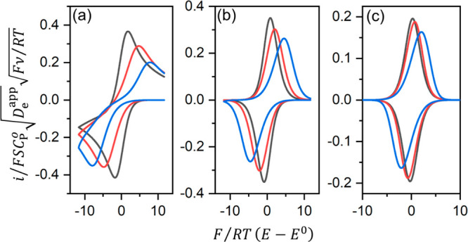
Simulated CVs of a molecular
redox film using a range of values
for the finite diffusion parameter λe: (a) = 7,
(b) 2, and (c) 0.7, each with varying magnitudes of the heterogeneous
electron transfer parameter Λs (black, 10; red, 1;
blue, 0.2). Current i is normalized to the semi-infinite
current ( ). The normalized electrode potential F/RT(E – E0) is plotted on the horizontal axis. Current–potential
responses were generated numerically with finite difference method.
). The normalized electrode potential F/RT(E – E0) is plotted on the horizontal axis. Current–potential
responses were generated numerically with finite difference method.
As expressed by λe, the transition
between these
two behaviors will occur on variation of either the scan rate or the
film thickness, approximately when λe is equal to
unity. Pushing the system from one regime to the other will provide
a method to extract the diffusion coefficient, if the film thickness
can be measured independently (e.g., SEM cross section imaging). For
example, in a recent report from our lab, a Zr-based MOF film containing
molecular Co catalysts (UU-100) showed that the CV peak current transitioned
from proportionality with ν to proportionality with  at ∼100 mV s–1.32 Since the film thickness was known,
it was possible to estimate Deapp as being on the order of 10–8 cm2 s–1, which matched
well with the value obtained from potential-step chronoamperometry
experiments. It should be noted that the CVs displayed in Figure 3 do not account for
non-idealities such as significant intermolecular interaction between
linkers that would lead to broadening of the faradaic waves,57,58 which may be encountered in the case of many MOF-based electrodes.
at ∼100 mV s–1.32 Since the film thickness was known,
it was possible to estimate Deapp as being on the order of 10–8 cm2 s–1, which matched
well with the value obtained from potential-step chronoamperometry
experiments. It should be noted that the CVs displayed in Figure 3 do not account for
non-idealities such as significant intermolecular interaction between
linkers that would lead to broadening of the faradaic waves,57,58 which may be encountered in the case of many MOF-based electrodes.
Deviations from the CVs in Figure 3, for example in the observed peak current, could also occur as a result of inhomogeneous film thickness (roughness).59,60 A method developed recently by Buesen et al. delivers a way to determine the film thickness under operating conditions (with the film in the solvated state).60 The authors demonstrated that deviations from the ideal behavior described above could be used to estimate film roughness, quantified as an ensemble thickness distribution.59 These are important parameters to measure and optimize (surface roughness, film thickness, and charge transport diffusion coefficients), since they are tied to the reaction-diffusion behavior of the system, as demonstrated by the Thiele modulus, and inevitably control catalytic performance, which we will see in the following sections.
Molecular Catalysis in MOF-Based Electrodes
The occurrence of diffusional transport of both charge and substrate presents a significant challenge in extracting kinetic parameters (rate constants or turnover frequencies, TOFs) and in identifying mechanistic pathways for molecular catalysis taking place in MOF films. Transport phenomena are often overlooked in the kinetic analysis of catalytic reactions occurring in MOFs, resulting in reporting of disguised kinetic parameters (TOFs, Tafel slopes, rate constant, or possibly reaction orders), due to unaccounted interference from mass or charge transport.12 Fortunately, there are well-developed reaction-diffusion models from mature tangential fields such as electrochemically mediated catalysis within redox polymer-modified electrodes (with covalently or ionically bound transition metal complexes)61−63 or using biocatalytic films,64−66 either of which may be relevant for analyzing MOF-based catalysts. This section outlines a steady reaction-diffusion kinetic model applicable to a simple one-electron, one-step catalytic reaction facilitated by a molecular catalyst incorporated in a MOF film, where the catalyst species is responsible for both the reaction with the substrate and shuttling of electrons through the film (Figure 4).67,68
Figure 4.

One-electron, one-step catalytic mechanism occurring in a molecular heterogenized MOF film electrode, where P and Q are the oxidized and reduced forms of the catalyst linker, respectively, S is the substrate, and k is the second-order rate constant for the catalytic reaction (kcat = kCS0).
Primarily three phenomena will determine the overall performance and steady-state current response of any catalytic process taking place within an electroactive MOF:
-
(1)
the intrinsic catalytic reaction
-
(2)
permeation and diffusion of the substrate
-
(3)
diffusional transport of electrons
Additional considerations for electron transfer kinetics at the electrode–film interface or a finite rate of mass transport of the substrate across the film–solution interface appear as boundary conditions in the overall reaction-diffusion problem and have been treated previously.68−71 If the substrate is depleted by the reaction and its concentration at the film–solution interface drops below its bulk value, ensuing mass transfer outside the film in solution can be treated as described previously for either rotating disk electrode voltammetry (RDEV) or CV.63,68 However, for simplicity, here we consider the concentration of substrate outside the film to be constant and equal to its bulk value. In general, Fick’s laws hold for statistically homogeneous microporous materials, and a continuum model for diffusion and any coupled reactions is valid.14 This will certainly apply to MOFs as well; however, as for any microporous material, extensions or adjustments to Fickian diffusion may be considered if required by the particular experimental system at hand.13,14,29,30,72 The following discussion focuses on the two diffusional phenomena and the catalytic reaction mentioned above, since these give rise to relativity unfamiliar complications resulting from reaction-diffusion—mainly that the concentration of each species will have a spatial dependence within the film. This is a fundamental characteristic of reactions coupled to diffusion occurring in porous media, where the possible existence of boundary layers, outside of which concentrations of substrate and/or intermediates drop to zero, needs to be taken into account.
Early reports first identified the three primary rate-limiting phenomena,73,74 for example by examining the mediated reduction of dibromoalkyl substrates by metalloporphyrin catalysts in multilayer films.75 A detailed kinetic model (outlined for steady-state techniques, RDEV) was soon after introduced by Andrieux, Dumas-Bouchiat, and Savéant,61 which recently has been updated by Costentin and Savéant for analysis by cyclic voltammetry including the case when the substrate is depleted in solution outside the film (total catalysis).67,68,76 The details of this model are briefly recalled in the next section in order to frame its application to molecular catalysis inside MOF films for the analysis that follows.
First of all, a steady-state situation will hold for the dynamical processes in the film when the catalytic reaction is fast as compared to the time scale of the experiment so that there is no accumulation of either reduced catalyst or substrate within the film.68 A mass balance on the system in this situation entails that the maximum current will be proportional to either the flux of reduced catalyst at the electrode interface or the flux of substrate at the film–solution interface.64 This situation is often referred to as pure kinetic conditions(68,77) and becomes important when analyzing reaction-diffusion phenomena of this type, as it simplifies the problem to a form where an analytical or semi-analytical solution for the current–potential response may be obtained. The rate of change of any species undergoing reaction-diffusion can be expressed as Fick’s second law plus a kinetic term accounting for the coupled chemical reaction. At steady state the time derivative is zero, giving
| 4 |
| 5 |
where x is the distance normal to the electrode surface with x = 0 located at the electrode–film interface, and k is the second-order rate constant of the catalytic reaction (see Figure 4). A simultaneous solution to these two equations given the appropriate boundary conditions will render the current–potential response.61,67,68,76
The three rate-limiting factors can each be expressed simply as a characteristic current density:62ik, ie, and is, for the catalytic reaction, charge transport, and substrate diffusion, respectively.
 |
6 |
where κS is the equilibrium partition coefficient for substrate crossing the film–solution interface, CP0 is the concentration of redox-active linkers, CS is the bulk concentration of substrate, and df is the film thickness (other terms are defined the same as above). The characteristic current densities are obtained from the hypothetical maximum flux for each potentially limiting process, displayed in Figure 5, and these describe the overall capacity of the film to deliver charge and substrate to the active sites to carry out the catalytic reaction at a given rate.78 They represent how the rate of each process (reaction or diffusion) scales under a given set of conditions and independent variables (eq 6). A single process or possibly two processes in parallel, reaction on one hand and a transport phenomenon on the other, may determine the overall observed current.
Figure 5.

Schematic illustration of limiting fluxes: FQ for diffusion-like charge transport and FS for substrate diffusion.78 The catalytic reaction is represented by a maximum production or generation rate of product per unit surface area (mol cm–2 s–1), Gk. Concentration profiles for each process are displayed, which give the corresponding characteristic current densities (ie, is, and ik, respectively) from multiplication of the magnitude of each flux or rate by F.
Akin to Thiele’s prediction, the behavior is governed by the ratio of the catalytic rate to either the rate of electron diffusion or substrate diffusion, precisely given by ratios of the characteristic current densities. Therefore, two dimensionless control parameters can be defined,63 noting their fundamental similarity to the Thiele modulus in eq 1:
 |
7 |
When one or both parameters are very large, transport limitations by substrate or electron-hopping diffusion are observed along with the appearance of boundary layers, which reduce the total amount of active catalyst within the film under operating conditions. Analytical solutions can be found in many limiting situations when there exists a linear gradient for either Q or S over a significant dimension of the film.63,68 This results in the limiting regimes shown in the zone diagram in Figure 6.63,68,69 It should be noted that there is no analytical solution for the general case (middle, Figure 6), and numerical methods to compute the solution to eq 4 and eq 5 must be employed.79,80 In the original formalism,61 a nomenclature for the limiting process(es) was established, and the letters R, S, and E are assigned to the catalytic reaction, substrate diffusion, and diffusional charge transport being limiting, respectively. Combinations thereof represent mixed kinetic control by two or more phenomena.
Figure 6.

Kinetic zone diagram for limiting cases of a one-step, one-electron catalytic reaction occurring in a multilayer film.69 Schematic concentration profiles of reduced catalyst Q (solid line) and substrate S (dotted line) are displayed in each zone. The definitions of is* and ik incorporate the possibility for substrate depletion at the film–solution interface and ensuing solution-phase mass transport outside the film.63 The navigation compass on the top right shows the magnitude and direction in which each experimental variable will translate the system within the zone diagram. Adapted from ref (69) with permission from Elsevier Science.
Using Film Thickness as a Diagnostic Tool for Reaction-Diffusion
The main analytic tool to diagnose the kinetic limitation occurring within the film is variation of the film thickness.67,68,76 This is the parameter that provides the most information and can in principle be varied systematically over a range of values. Very intuitively it can be expected that thicker films will lead to limitations by mass or charge transport. For a simple example, consider the case where electron-hopping diffusion is relatively fast (iS ≪ ie) compared to the rate at which substrate diffuses through the film, and κS is approximately unity (Figure 7).76
Figure 7.

(a) Steady-state CVs with increasing film thickness from df = 10 nm (black) to df = 640 nm (orange). (b) Corresponding plot of steady-state plateau current density (jpl, blue dots) vs df when is ≪ ie with Deapp = 1 × 10⁻⁵ cm2 s–1, DS = 1 × 10⁻¹⁰ cm2 s–1, k = 10 M–1 s–1, CS = 1 M, CP0 = 0.1 M, and κS = 1.
Starting with very thin films, the measured catalytic plateau current will be proportional to the film thickness, as the catalytic reaction encompasses the entirety of the volume contained inside the film (zone R, eq 8). With thicker films, this current reaches a limiting value and no longer varies with df (zone SR, eq 9). Now, the catalytic reaction and substrate diffusion jointly limit the observed current density. Plotting the plateau current density versus the film thickness, will allow for estimating the intrinsic characteristics of the film. The slope in the limit of thin films is proportional to the intrinsic reaction rate constant k, where CP0 and CS are either known or can be measured. In the region where the current is invariant with df, the limiting current can be used to calculate DS (eq 9), since k has been determined.68,76
| 8 |
| 9 |
where S is
the geometric surface area (cm2). Analogously, when substrate
diffusion is much faster than electron hopping (is ≫ ie) and the catalytic
reaction is fast compared to diffusion-like charge transport ( ≫ 1), the steady-state plateau current
is given by67
≫ 1), the steady-state plateau current
is given by67
| 10 |
While the theoretical model presented here is well established,81 such an analysis has never, to the best of our knowledge, been done with catalytic MOF films.
Kinetic Analysis of MOF-Based Catalysis Relies on Identifying and Characterizing Boundary Layers
Above, we saw that the
current saturates upon increasing the film thickness, perturbing the
system into a regime where both reaction and diffusion are now both
limiting the overall current. This situation arises principally because
the reaction consumes the substrate before it diffuses into the interior
of the film forming a boundary layer near the film–solution
interface. This is important because the current density in zone SR
(eq 9) is proportional
to the thickness of the resulting boundary layer. As this becomes
thinner, there are fewer active catalysts, and thus, lower overall
catalytic efficiency. A scaling relationship of Fick’s second
law can show how to (very simply) calculate reaction-diffusion layer
thickness and total active catalyst concentration.
Taking eq 5 when is ≪ ie and  ≫ 1 (zone SR) and again for simplicity
assuming κS = 1,
≫ 1 (zone SR) and again for simplicity
assuming κS = 1,
| 11 |
If we assume concentrations scale with the corresponding total or bulk concentration of each species (at E ≪ EP/Q0) and the distance perpendicular to the electrode surface is rescaled to the size of the reaction-diffusion layer (δrxn), then eq 11 becomes
After rearranging, the reaction-diffusion layer thickness is given by
| 12 |
The active portion of catalyst (mQactive, with units of moles) can then be found by integrating over the reaction-diffusion layer thickness:
Finally, this results in
| 13 |
Interestingly, since the
reaction is first-order in substrate, in this situation increasing
the bulk concentration of substrate outside the film does not in fact
help alleviate the transport limitation by substrate diffusion (the
active catalyst concentration is independent of CS0). The complementary
expression for when charge transport is jointly limiting with the
catalytic reaction and substrate diffusion is fast (iS ≫ ie and  ≫ 1, zone ER) is
| 14 |
In this case increasing the substrate concentration accelerates the reaction, causes the reaction-diffusion layer to decrease in thickness, and reduces the amount of active catalyst—all exacerbating the limitation by diffusional charge transport. It should be noted that these effects apply to the efficiency of the catalytic film in terms of the fraction of catalyst participating in the reaction, and ultimately put a limit on how thick the film can be made without having unused catalytic sites within the film. Since the reaction is first-order in substrate, increasing the bulk substrate concentration will, however, increase the overall current accordingly (see eqs 8, 9, and 10).
Falsified Kinetics and TOFs That Depend on Film Thickness
Since the chemical reactions occurring in MOFs are innately coupled to diffusive charge or mass transport, situations arise where measured kinetic parameters such as rate constants, reaction orders, TOFs, and activation energies do not reflect intrinsic values. Internal transport limitations by mass or charge diffusion will disguise kinetic values, resulting in what is designated from the traditional chemical engineering vernacular as “falsified kinetics”.21 In a classic example from basic chemical reaction engineering,13,21 the apparent or measured reaction order n′ in substrate (CS) can be related to the true reaction order n by
| 15 |
valid
for the situation when
substrate diffusion and the catalytic reaction are jointly limiting
(iS ≪ ie and  ≫ 1; zone SR, i.e., when the substrate
is present in a thin boundary layer at the film–solution interface,
and κS = 1). Conversely, in the case where electron
diffusion is slow (ie ≪ iS and
≫ 1; zone SR, i.e., when the substrate
is present in a thin boundary layer at the film–solution interface,
and κS = 1). Conversely, in the case where electron
diffusion is slow (ie ≪ iS and  ≫ 1, zone ER), the apparent reaction
order for substrate is given by
≫ 1, zone ER), the apparent reaction
order for substrate is given by
| 16 |
(i.e., when the reduced catalyst is present in a thin boundary layer at the electrode–film interface).67,77 Unless transport limitations are identified or the system is pushed to a regime where only the catalytic reaction is limiting and all gradients are eliminated (see zone R, Figure 6), mechanistic conclusions normally sought from uncorrected kinetic measurements will certainly contain artifacts.
Similarly, using the expression defined in eq 14, recall that TOFs can depend on film thickness,10,82
where TOFmaxtrue reflects
the intrinsic reaction rate of
the catalyst. This example is given for when iS ≫ ie and  ≫ 1 (zone ER and κS = 1). Indeed, the apparent
turnover frequency, TOFmax, will have different expressions
in each limiting regime, and when transport limitations are present,
TOFmaxapp will
underestimate TOFmax. Additionally, comparing different catalytic MOF films
using conflicting TOF values may encumber kinetic benchmarking and
comparison between such materials since the film thickness is not
necessarily a parameter intrinsic to the material (i.e., it can be
varied by using different synthetic routes or fabrication techniques).
Consequently, given a new catalytic MOF, diagnosing the limiting regime
(zone diagram, Figure 6) under operating conditions, identifying and quantifying any possible
boundary layers that may arise, and extracting intrinsic parameters
of the system (DS, Deapp, TOFmax) are important
endeavors to advance the field of MOF-based catalysis.
≫ 1 (zone ER and κS = 1). Indeed, the apparent
turnover frequency, TOFmax, will have different expressions
in each limiting regime, and when transport limitations are present,
TOFmaxapp will
underestimate TOFmax. Additionally, comparing different catalytic MOF films
using conflicting TOF values may encumber kinetic benchmarking and
comparison between such materials since the film thickness is not
necessarily a parameter intrinsic to the material (i.e., it can be
varied by using different synthetic routes or fabrication techniques).
Consequently, given a new catalytic MOF, diagnosing the limiting regime
(zone diagram, Figure 6) under operating conditions, identifying and quantifying any possible
boundary layers that may arise, and extracting intrinsic parameters
of the system (DS, Deapp, TOFmax) are important
endeavors to advance the field of MOF-based catalysis.
One experimental
example for CO2 reduction (Figure 8)83 demonstrates
the impact of thick films and ensuing mass
or charge transport limitations on the observed current density. Starting
from the thinnest films examined, an increase in film thickness led
to an approximately linear increase in the total current density (Figure 8), corresponding
to the R limiting regime recalled from the zone diagram in Figure 6. Here the entire
film is active since the reaction-diffusion layer is larger than the
film thickness (i.e.,  ≪ 1 or
  ), and the transport processes
are able
to supply charge or substrate across the entire film before being
consumed by the reaction. In these limits, turnover frequencies measured
in the usual way will yield TOFmaxtrue. For example, Kornienko et al. reported
a TOF value from data taken under these conditions on the order of
0.06 s–1 (Figure 8).83
), and the transport processes
are able
to supply charge or substrate across the entire film before being
consumed by the reaction. In these limits, turnover frequencies measured
in the usual way will yield TOFmaxtrue. For example, Kornienko et al. reported
a TOF value from data taken under these conditions on the order of
0.06 s–1 (Figure 8).83
Figure 8.

Influence of film thickness on overall steady-state current density demonstrating interference from transport phenomena. CO2 reduction to CO catalyzed by Al2(OH)2TCPP-Co (TCPP-H2 = 4,4′,4″,4‴-(porphyrin-5,10,15,20-tetrayl)tetrabenzoate) films of different thickness (50 ALD cycles correspond to a film thickness approximately of 30–70 nm).83 Adapted from ref (83) with permission from the American Chemical Society.
However, upon increasing the film thickness further, the MOF films
exhibit a saturation in the total observed current density followed
by a sharp decline (Figure 8).83 The transition from the linear
region to this peaked region is expected to correspond to the situation
where on the time scale of the reaction, diffusional mass or charge
transport are not able to supply electrons or substrate over the entire
length of the film (i.e.,  > 1 or
  > 1). Since now the film thickness has
exceeded the size of the reaction-diffusion layer, a boundary layer
would be expected at either the electrode–film interface or
the film–solution interface depending on the relative rates
of electron-hopping and substrate diffusion (as compared to the catalytic
reaction) within the film. Further increase in the film thickness
leads to a drop in current as the second diffusional process becomes
limiting as well and the film most probably enters either the SR+E
or ER+S situation.68 In these limits, as
soon as
> 1). Since now the film thickness has
exceeded the size of the reaction-diffusion layer, a boundary layer
would be expected at either the electrode–film interface or
the film–solution interface depending on the relative rates
of electron-hopping and substrate diffusion (as compared to the catalytic
reaction) within the film. Further increase in the film thickness
leads to a drop in current as the second diffusional process becomes
limiting as well and the film most probably enters either the SR+E
or ER+S situation.68 In these limits, as
soon as  or
or  becomes greater than unity, TOFmaxapp ≠ TOFmax, and uncorrected
kinetic values will be falsified, since the bulk concentration of
catalyst is no longer reflective of the amount of active catalyst
contained within the boundary layer. It should be noted, from this
example it is not possible to conclude which transport process (either
substrate diffusion or charge transport) initially limits the current
as the film thickness is increased. This would require additional
information, particularly the rate at which the substrate (CO2 or possibly protons) diffuse through the MOF films. Additionally,
the authors identified several other factors that may contribute to
the observed effect on the current density and which may complicate
the analysis of these data in terms of reaction-diffusion. For example,
Al2(OH)2TCPP-Co films with the largest thickness
may have an underlying layer of aluminum oxide between the conducting
FTO surface and the MOF film, which is remaining from the film synthesis
and fabrication.83 If this layer is sufficiently
thick, it would reduce the ohmic contact between the film and conducting
substrate, producing lower currents. In short, while this example
is one of the few reports to systematically examine the effect of
MOF film thickness on catalysis and certainly reveals important effects
associated with thick films, overall these results point toward a
need for improved methods of film synthesis and fabrication methods
for MOFs on electrodes with controllable film thickness and morphology.
becomes greater than unity, TOFmaxapp ≠ TOFmax, and uncorrected
kinetic values will be falsified, since the bulk concentration of
catalyst is no longer reflective of the amount of active catalyst
contained within the boundary layer. It should be noted, from this
example it is not possible to conclude which transport process (either
substrate diffusion or charge transport) initially limits the current
as the film thickness is increased. This would require additional
information, particularly the rate at which the substrate (CO2 or possibly protons) diffuse through the MOF films. Additionally,
the authors identified several other factors that may contribute to
the observed effect on the current density and which may complicate
the analysis of these data in terms of reaction-diffusion. For example,
Al2(OH)2TCPP-Co films with the largest thickness
may have an underlying layer of aluminum oxide between the conducting
FTO surface and the MOF film, which is remaining from the film synthesis
and fabrication.83 If this layer is sufficiently
thick, it would reduce the ohmic contact between the film and conducting
substrate, producing lower currents. In short, while this example
is one of the few reports to systematically examine the effect of
MOF film thickness on catalysis and certainly reveals important effects
associated with thick films, overall these results point toward a
need for improved methods of film synthesis and fabrication methods
for MOFs on electrodes with controllable film thickness and morphology.
Opportunities and Challenges
Understanding the fundamental kinetics of MOF-based catalysis using molecular active sites is still a major challenge for the field. Where is the bottleneck for catalysis, and how can the unique properties of MOFs be exploited for optimization? Incorporating the foundational principles from the reaction-diffusion models described above, this next section attempts to analyze each potentially limiting process in turn, with suggestions for increasing catalytic efficiency in ways that are uniquely suited to MOFs.
Limiting Electron Diffusion
As an
illustrative example,
a situation with limitations by electron-hopping diffusion is displayed
in Figure 9. In this
situation substrate transport is relatively fast (is ≫ ie),67 or the bulk concentration of the substrate is
very high (for example when the substrate is the solvent). This may
be encountered in practice with catalytic MOF films having large pores
allowing facile substrate diffusion, but slow charge transport due
to a large separation between redox-active linkers28 (Deapp = 10–10–10–14 cm2 s–1).2 Catalytic steady-state current (at E ≪ EP/Q) is plotted versus the dimensionless parameter  =
=  (Figure 9a), which
is the ratio of the catalytic reaction rate
to the rate of diffusional charge transport. An insightful alternative
definition can be expressed based on a geometric length scale present
in the problem (df) and a physical length
scale for reaction-diffusion. Consequently, this parameter is also
equivalent to the ratio of the film thickness to the thickness of
the reaction-diffusion layer. As the electron-hopping diffusion coefficient
decreases, the current (normalized to the reaction-limited current, iR = FSkκSCS0CPdf) drops markedly. The blue and
black dots in Figure 9 and the corresponding concentration profiles in Figure 9 represent electron-hopping
diffusion coefficients in a realistic range for electroactive MOF
films.30,34,51,84 The current in this situation is controlled by both
the catalytic reaction and electron diffusion and is no longer a function
of film thickness, and the reaction is fast enough compared with diffusion
to cause finite gradients of the reduced catalyst to form within the
film. Thus, the reaction-diffusion layer is significantly smaller
than the film thickness; and therefore, increasing the number of layers
(increasing the thickness) is unproductive, because the outer region
of the film will not participate in the catalytic reaction.67 The y-axis in Figure 9 is a measure of catalytic
efficiency (how much of the film is active in the reaction), and accordingly
it can be seen that large values of
(Figure 9a), which
is the ratio of the catalytic reaction rate
to the rate of diffusional charge transport. An insightful alternative
definition can be expressed based on a geometric length scale present
in the problem (df) and a physical length
scale for reaction-diffusion. Consequently, this parameter is also
equivalent to the ratio of the film thickness to the thickness of
the reaction-diffusion layer. As the electron-hopping diffusion coefficient
decreases, the current (normalized to the reaction-limited current, iR = FSkκSCS0CPdf) drops markedly. The blue and
black dots in Figure 9 and the corresponding concentration profiles in Figure 9 represent electron-hopping
diffusion coefficients in a realistic range for electroactive MOF
films.30,34,51,84 The current in this situation is controlled by both
the catalytic reaction and electron diffusion and is no longer a function
of film thickness, and the reaction is fast enough compared with diffusion
to cause finite gradients of the reduced catalyst to form within the
film. Thus, the reaction-diffusion layer is significantly smaller
than the film thickness; and therefore, increasing the number of layers
(increasing the thickness) is unproductive, because the outer region
of the film will not participate in the catalytic reaction.67 The y-axis in Figure 9 is a measure of catalytic
efficiency (how much of the film is active in the reaction), and accordingly
it can be seen that large values of  cause a reaction-diffusion layer to form
that reduces the efficiency of the system (i.e., diffusion is not
able to support charge transport to all the catalytic sites on the
time scale of the reaction, see concentration profiles in Figure 9b).
cause a reaction-diffusion layer to form
that reduces the efficiency of the system (i.e., diffusion is not
able to support charge transport to all the catalytic sites on the
time scale of the reaction, see concentration profiles in Figure 9b).
Figure 9.

(a) Variation of the
steady-state plateau current (at E ≪ EP/Q0) with  =
=  when substrate
concentration is constant
throughout the film (is ≫ ie). (b) Corresponding concentration profiles
of Q: df = 1 μm, CP = 1 M, and kκSCS0 = 10 s–1, and De = (red) 1.3 × 10⁻⁶ cm2 s–1, (green) 2 × 10⁻⁷ cm2 s–1, (yellow) 5 × 10⁻⁸ cm2 s–1, (blue) 5.5 × 10⁻⁹ cm2 s–1, (black) 5 × 10⁻¹⁰ cm2 s–1.
when substrate
concentration is constant
throughout the film (is ≫ ie). (b) Corresponding concentration profiles
of Q: df = 1 μm, CP = 1 M, and kκSCS0 = 10 s–1, and De = (red) 1.3 × 10⁻⁶ cm2 s–1, (green) 2 × 10⁻⁷ cm2 s–1, (yellow) 5 × 10⁻⁸ cm2 s–1, (blue) 5.5 × 10⁻⁹ cm2 s–1, (black) 5 × 10⁻¹⁰ cm2 s–1.
Limiting Substrate Diffusion
The situation of kinetically
limiting substrate diffusion within the film in addition to charge
transport is shown in Figure 10.68 Representative conditions found
for MOF films34,54 were used to generate concentration
profiles: Deapp = 5 × 10⁻¹⁰ cm2 s–1, df = 1
μm, CP = 1 M, with various values
of DS. An important situation arises when  ≫ 1 and
  ≫ 1. The observed current density
is independent of the rate of the catalytic reaction and the only
limitations are from substrate diffusion and/or charge transport.
This is represented in Figure 10c, displaying zone S+E. In fact, when the transport
processes are much slower than the reaction rate, the reaction-diffusion
layer approaches the size of a monolayer, which can be located at
either interface (either the electrode–film interface, zone
S, or the film–solution interface, zone E).61,64 The overall current density is plotted in Figure 10e for each value of DS, corresponding to the concentration profiles in Figure 10a–d. Typical
surface concentrations and electron-hopping transport parameters reported
in literature indeed show that catalytic MOF films are able to reach
the recognized minimum 10 mA cm–2 needed for large-scale
applications85 with a moderately active
catalyst (25 turnovers per second); however, with a typical film thicknesses df = 1 μm the efficiency is rather low
(see the shaded region in Figure 10 indicating the size of the reaction-diffusion layer).
Importantly, this assumes facile substrate transport through the film
(Figure 10, DS = 10–5 cm2 s–1) more typical of a freely diffusing species in solution.
As the substrate diffusion coefficient is decreased below 10–7 cm2 s–1 while holding all other values
constant, a sharp decline in steady-state current density is observed
(Figure 10e). As an
example of typical diffusion rates, the diffusivities of tertiary
amines (triethylamine, tripropylamine, etc.) through solvent-filled
pores of a Zn MOF ([Zn2L0.5(BPDC)2]3·9DMF·9H2O) were quantified in
the range of 10–9–10–10 cm2 s–1.86 However, we note that alkyl amines may not be representative of
typical small molecule substrates for energy conversion applications.
Clearly there is room for the field and in particular for electrochemistry
as a technique to aid in the quantitative measurement of diffusion
rates of small molecules through MOFs under conditions relevant to
catalysis (solvated). Overall, the simulated results presented here
preliminarily suggest that a combination of substrate diffusion and
charge transport may be kinetically limiting in many MOF-based catalytic
films of average thickness (∼1 μm); however, certainly
more experimental studies addressing catalysis and transport phenomena
are needed to fully assign the kinetic behavior of many catalytic
MOFs.
≫ 1. The observed current density
is independent of the rate of the catalytic reaction and the only
limitations are from substrate diffusion and/or charge transport.
This is represented in Figure 10c, displaying zone S+E. In fact, when the transport
processes are much slower than the reaction rate, the reaction-diffusion
layer approaches the size of a monolayer, which can be located at
either interface (either the electrode–film interface, zone
S, or the film–solution interface, zone E).61,64 The overall current density is plotted in Figure 10e for each value of DS, corresponding to the concentration profiles in Figure 10a–d. Typical
surface concentrations and electron-hopping transport parameters reported
in literature indeed show that catalytic MOF films are able to reach
the recognized minimum 10 mA cm–2 needed for large-scale
applications85 with a moderately active
catalyst (25 turnovers per second); however, with a typical film thicknesses df = 1 μm the efficiency is rather low
(see the shaded region in Figure 10 indicating the size of the reaction-diffusion layer).
Importantly, this assumes facile substrate transport through the film
(Figure 10, DS = 10–5 cm2 s–1) more typical of a freely diffusing species in solution.
As the substrate diffusion coefficient is decreased below 10–7 cm2 s–1 while holding all other values
constant, a sharp decline in steady-state current density is observed
(Figure 10e). As an
example of typical diffusion rates, the diffusivities of tertiary
amines (triethylamine, tripropylamine, etc.) through solvent-filled
pores of a Zn MOF ([Zn2L0.5(BPDC)2]3·9DMF·9H2O) were quantified in
the range of 10–9–10–10 cm2 s–1.86 However, we note that alkyl amines may not be representative of
typical small molecule substrates for energy conversion applications.
Clearly there is room for the field and in particular for electrochemistry
as a technique to aid in the quantitative measurement of diffusion
rates of small molecules through MOFs under conditions relevant to
catalysis (solvated). Overall, the simulated results presented here
preliminarily suggest that a combination of substrate diffusion and
charge transport may be kinetically limiting in many MOF-based catalytic
films of average thickness (∼1 μm); however, certainly
more experimental studies addressing catalysis and transport phenomena
are needed to fully assign the kinetic behavior of many catalytic
MOFs.
Figure 10.

Progressively slower substrate diffusion: simulated concentration
profiles of oxidized catalyst P (red), reduced catalyst Q (black),
and substrate S (blue) using finite difference method using Deapp = 5 × 10⁻¹⁰ cm2 s–1, df = 1 μm, CP = 1 M, κSCS0 = 0.1 M, and kκSCS = 25 s–1, with DS from (a) 5 × 10⁻⁵, (b) 5 ×
10–7, (c) 5 × 10⁻⁹, to (d)
5 × 10–11 cm2 s–1. Substrate concentration within the film (blue lines, CS) is normalized to the substrate concentration at the
film–solution interface (equal to κSCS0). Below each concentration profile the normalized local current
density (cyan) as a function of distance from the electrode (x) normalized to the film thickness is shown. The shaded
region indicates the location of the reaction-diffusion layer inside
the film. (e) Calculated steady-state current density (at E ≪ EP/Q) corresponding to the concentration
profiles in part (a) through (d) plotted as a function of  with the value of DS shown next to each
point. Other parameters are the same as
above (Deapp = 5 × 10⁻¹⁰ cm2 s–1, df = 1
μm, CP = 1 M, κSCS0 = 0.1 M,
and kκSCS = 25 s–1).
with the value of DS shown next to each
point. Other parameters are the same as
above (Deapp = 5 × 10⁻¹⁰ cm2 s–1, df = 1
μm, CP = 1 M, κSCS0 = 0.1 M,
and kκSCS = 25 s–1).
Opportunities
Future efforts toward improving or designing molecular catalysis in MOF films should include utilizing reaction-diffusion models (such as the simple one recalled above) to characterize charge and mass transport rates. However, importantly, deployment of these types of porous catalyst materials at scale requires optimizing both catalyst reactivity and transport properties concurrently. Avoiding transport limitations might require decelerating the catalytic rate so that it is slower than diffusive transport by operating the catalytic MOF film at lower current densities. However, this is not very effective for fast conversion of substrate to product on a large scale. Conversely, running the overall process at higher current densities (where the catalytic reaction is much faster than the diffusional processes) quickly becomes inefficient as transport limitations restrict the amount of active catalyst via the formation of boundary layers. Finding the most efficient operating conditions between these two scenarios can only be done when the intrinsic chemical reactivity of the catalyst toward the substrate and the transport properties of the catalyst support matrix are examined, characterized, and optimized together. For MOF-based molecular catalysis, this means that modifying the reactivity of the molecular catalyst alone is not enough to progress toward realistic applications of these materials, and significant efforts must be made to design these systems so as to balance chemical reactivity with the diffusional transport phenomena outlined here.
Once the transport parameters (diffusion coefficients)
and intrinsic reaction kinetics are measured and the rate-limiting
process or processes is identified, a clear step forward is to improve
these limitations by one of two methods. As shown above, MOF films
are indeed able to reach high current densities of industrial relevance
(10 mA cm–2). However, often the efficiency (what
fraction of the catalysts are active in the film) is less than ideal,
making these systems difficult to scale-up to meet requirements for
applications. The first and most straightforward strategy is to modify
the film to an optimal thickness where  ≈ 1
and
≈ 1
and  ≈ 1.15,67,68 Practical methods to make MOF films in a controlled
manner are critical in this endeavor.87,88 Optimizing
film thickness is displayed in Figure 11 (green curve) assuming facile substrate
transport for simplicity, where starting from Deapp = 5 × 10⁻¹⁰ cm2 s–1, a 1 μm
film produces 10 mA cm–2 of current. Decreasing
the film thickness from 1 μm to 100 nm (process I in Figure 11a) improves the
overall efficiency to where nearly all the catalysts are active, while
maintaining the same current density. However, the rates of substrate
and electron-hopping diffusion set an upper limit on how thick the
film can be made (i.e., no larger than the reaction-diffusion layer
thickness), and thus bounds the overall rate of product formation.
Alternatively, tuning the molecular building blocks is a unique property
of MOFs that can be used to modify macroscopic transport properties—something
that is relatively more difficult to accomplish in other porous materials
lacking molecularly discrete components. Using the same example (Figure 11a), increasing De from 5 × 10⁻¹⁰ cm2 s–1 to 5 × 10⁻⁸ cm2 s–1 (process II in Figure 11a) gives an even higher current density of about 20 mA cm–2 and unity catalyst efficiency with the same 100 nm
film (Figure 11, red
curve). Now with faster charge transport properties, the catalytic
MOF film can be made thicker (up to the point where
≈ 1.15,67,68 Practical methods to make MOF films in a controlled
manner are critical in this endeavor.87,88 Optimizing
film thickness is displayed in Figure 11 (green curve) assuming facile substrate
transport for simplicity, where starting from Deapp = 5 × 10⁻¹⁰ cm2 s–1, a 1 μm
film produces 10 mA cm–2 of current. Decreasing
the film thickness from 1 μm to 100 nm (process I in Figure 11a) improves the
overall efficiency to where nearly all the catalysts are active, while
maintaining the same current density. However, the rates of substrate
and electron-hopping diffusion set an upper limit on how thick the
film can be made (i.e., no larger than the reaction-diffusion layer
thickness), and thus bounds the overall rate of product formation.
Alternatively, tuning the molecular building blocks is a unique property
of MOFs that can be used to modify macroscopic transport properties—something
that is relatively more difficult to accomplish in other porous materials
lacking molecularly discrete components. Using the same example (Figure 11a), increasing De from 5 × 10⁻¹⁰ cm2 s–1 to 5 × 10⁻⁸ cm2 s–1 (process II in Figure 11a) gives an even higher current density of about 20 mA cm–2 and unity catalyst efficiency with the same 100 nm
film (Figure 11, red
curve). Now with faster charge transport properties, the catalytic
MOF film can be made thicker (up to the point where  ≈ 1, process III in Figure 11a) without compromising efficiency,
reaching a maximum of 100 mA cm–2 with 1 μm
thick films. Designing the pore environment to facilitate charge or
substrate transport by synthetic tuning of the linkers or by well-established
reticular chemistry89,90 is thus a distinct advantage
available to MOF materials. Ultimately, this will allow thicker films
to be used, which do not display transport limitations, giving higher
overall catalyst efficiency and higher rates of production.
≈ 1, process III in Figure 11a) without compromising efficiency,
reaching a maximum of 100 mA cm–2 with 1 μm
thick films. Designing the pore environment to facilitate charge or
substrate transport by synthetic tuning of the linkers or by well-established
reticular chemistry89,90 is thus a distinct advantage
available to MOF materials. Ultimately, this will allow thicker films
to be used, which do not display transport limitations, giving higher
overall catalyst efficiency and higher rates of production.
Figure 11.

(a) Options
for optimizing MOF-based molecular catalysis either
by adjustment of the film thickness or by increasing one or more diffusion
coefficients by modifying the pore structure/properties via linker
design. The example shown here applies to when electron-hopping diffusion
is much slower than substrate transport (is ≫ ie). The shaded region below
each curve signifies film thicknesses where the efficiency is less
than unity and the amount of active catalyst is less than the amount
of total catalyst. In (a), the observed current density is plotted
versus the film thickness (df) for two
different values of Deapp, 5 × 10⁻¹⁰ cm2 s–1 (green curve) and 5 × 10⁻⁸ cm2 s–1 (red curve). Other parameters
are the same as above: CP = 1 M, κSCS0 = 0.1 M,
and kκSCS = 25 s–1. (b) Effect of different intrinsic catalyst turnover frequencies, kκSCS0 = 25 s–1 (green
curve) and kκSCS = 250 s–1 (blue curve), on observed current density with Deapp = 5 × 10⁻¹⁰ cm2 s–1, CP = 1 M, and κSCS0 = 0.1 M. (c) Double
logarithmic plot of catalyst efficiency (red curve, left axis) and
observed current density normalized to the electron diffusion limited
current density,  (black curve, right axis), versus the dimensionless
control parameter
(black curve, right axis), versus the dimensionless
control parameter  =
=  . Optimal catalytic performance is obtained
at the intersection of these two curves when
. Optimal catalytic performance is obtained
at the intersection of these two curves when  = 1 (shaded circle).
It is interesting to
note that the current densities in this simple
example (≥10 mA cm–2) could be achieved with
a relatively slow intrinsic rate of turnover (25 s–1) for the molecular catalyst covalently incorporated in the MOF.
This is certainly due to the relatively high concentration of active
sites within the MOF film (10–100 nmol cm–2 is a typical range32,34,83). If the intrinsic rate of the molecular catalyst were increased
further, this would allow one to make thinner films utilizing less
material and achieve higher current densities. This is shown in Figure 11 where an increasing
in kcat by an order of magnitude for the
same charge transport rate (Deapp = 5 × 10⁻¹⁰ cm2 s–1 and df = 0.1 μm) increases the observed current density from
10 to 30 mA cm–2 (process IV, Figure 11b). Reducing the film thickness
(process V, Figure 11b) is then an option for achieving optimal efficiency. Overall, a
common theme in all the examples presented here is the realization
that reaction-diffusion leads to a balance between catalyst efficiency
(amount of used catalyst within the film) and the total rate of production
(observed current density), as depicted in Figure 11c. Optimal catalytic performance (highest
efficiency and highest current density) is obtained when  = 1 (Figure 11c,
intersection between red and black curves).67
= 1 (Figure 11c,
intersection between red and black curves).67
Conclusion
Metal–organic frameworks are excellent candidates for support matrices in which to incorporate molecular catalysts. A major advantage to this strategy is the synthetic tunability of both the framework and the catalyst at the molecular scale. At present, however, a notable barrier to this realization and to the eventual application of these materials to catalytic processes at industrial scale is the coupling of transport phenomena to traditional chemical kinetics, as a consequence of immobilization of the molecular species in a finite 3D porous structure. However, once transport by diffusion is quantitatively analyzed and taken into account using simple and well-established reaction-diffusion kinetic models, first introduced by Thiele and Damköhler in the 1930s, optimizing the pore structure of the framework for facile diffusive transport could yield highly efficient catalytic materials as well as a deeper understanding of the intrinsic kinetics and mechanisms of the molecular catalyst under operating condition inside the MOF-film structure. MOFs are uniquely suited to this task due to the structure–property relationship between their molecular-level building blocks and their macroscopic physical and chemical properties. The kinetic information gained from the analysis presented here can be in turn used to inform molecular-level design that will best elevate metal–organic frameworks toward becoming suitable for applications as high-performance catalysts for the electrochemical activation and conversion of small molecules.
Acknowledgments
Financial support from the European Research Council via Project ERC-CoG2015-681895_MOFcat is gratefully acknowledged. A.M.B. was supported by the Olle Engkvist Byggmästare Foundation.
Glossary
Symbols
- Cj
concentration of species j (M, mol cm−3)
- CPo
total electroactive concentration of redox-active linker, P (M, mol cm−3)
- CSo
bulk concentration of substrate (M, mol cm−3)
- df
film thickness (cm)
- d
average hopping distance (cm)
- De
electron hopping diffusion coefficient (cm2 s−1)
- Deapp
apparent charge transport diffusion coefficient (cm2 s−1)
- DS
intra-MOF diffusion coefficient of substrate (cm2 s−1)
- E
electrode potential (V)
- E0
standard potential (V)
- Fj
molar flux of species j (mol cm−2 s−1)
- F
Faraday constant (C mol−1)
- Gk
production/consumption rate of chemical reaction per unit surface area (mol cm−2 s−1)
- i
current (A)
- ipl
plateau or limiting steady state current (A)
- is
characteristic current density for substrate diffusion within film (A cm−2)
- ie
characteristic current density for diffusional charge transport (A cm−2)
- ik
characteristic current density for catalytic reaction (A cm−2)
- j
current density (A cm−2)
- jpl
plateau or limiting steady state current density (A cm−2)
- k
second order rate constant of chemical step (M−1 s−1, cm3 mol−1 s−1)
- kcat
observed first order catalytic rate constant (s−1)
- ke
self-exchange rate constant occurring only in direction normal to electrode (M−1 s−1, cm3 mol−1 s−1)
- kex
self-exchange rate constant (M−1 s−1, cm3 mol−1 s−1)
- ks
standard interfacial rate constant (cm s−1)
- mQactive
moles of active catalyst in MOF film (mol)
- n′
apparent reaction order in substrate
- n
true reaction order in substrate
- r
radial distance (cm)
- R
gas constant (J mol−1 K−1)
- Ra
MOF particle radius (cm)
- S
surface area (cm2)
- t
time (s)
- TOFmaxapp
maximum apparent turnover frequency (s−1)
- TOFmaxtrue
maximum true turnover frequency (s−1)
- x
distance in Cartesian coordinates perpendicular to electrode surface (cm)
- δrxn
reaction-diffusion layer thickness (cm)
- δ
diffusion layer thickness (cm)
- κS
partition equilibrium constant for substrate crossing MOF film-solution interface
- ν
scan rate (V s−1)
Supporting Information Available
The Supporting Information is available free of charge at https://pubs.acs.org/doi/10.1021/jacs.0c02899.
CV simulations and corresponding concentration profiles of electron-hopping diffusion occurring in a MOF film (MP4)
The authors declare no competing financial interest.
Supplementary Material
References
- Downes C. A.; Marinescu S. C. Electrocatalytic Metal-Organic Frameworks for Energy Applications. ChemSusChem 2017, 10 (22), 4374–4392. 10.1002/cssc.201701420. [DOI] [PubMed] [Google Scholar]
- McCarthy B. D.; Beiler A. M.; Johnson B. A.; Liseev T.; Castner A. T.; Ott S. Analysis of Electrocatalytic Metal-Organic Frameworks. Coord. Chem. Rev. 2020, 406, 213137. 10.1016/j.ccr.2019.213137. [DOI] [PMC free article] [PubMed] [Google Scholar]
- Majewski M. B.; Peters A. W.; Wasielewski M. R.; Hupp J. T.; Farha O. K. Metal–Organic Frameworks as Platform Materials for Solar Fuels Catalysis. ACS Energy Lett. 2018, 3 (3), 598–611. 10.1021/acsenergylett.8b00010. [DOI] [Google Scholar]
- Zhou H.-C.; Long J. R.; Yaghi O. M. Introduction to Metal–Organic Frameworks. Chem. Rev. 2012, 112 (2), 673–674. 10.1021/cr300014x. [DOI] [PubMed] [Google Scholar]
- Furukawa H.; Cordova K. E.; O’Keeffe M.; Yaghi O. M. The Chemistry and Applications of Metal-Organic Frameworks. Science 2013, 341 (6149), 123044. 10.1126/science.1230444. [DOI] [PubMed] [Google Scholar]
- Tanabe K. K.; Cohen S. M. Postsynthetic Modification of Metal–Organic Frameworks—a Progress Report. Chem. Soc. Rev. 2011, 40 (2), 498–519. 10.1039/C0CS00031K. [DOI] [PubMed] [Google Scholar]
- Cohen S. M. The Postsynthetic Renaissance in Porous Solids. J. Am. Chem. Soc. 2017, 139 (8), 2855–2863. 10.1021/jacs.6b11259. [DOI] [PubMed] [Google Scholar]
- Cohen S. M.; Zhang Z.; Boissonnault J. A. Toward “MetalloMOFzymes”: Metal–Organic Frameworks with Single-Site Metal Catalysts for Small-Molecule Transformations. Inorg. Chem. 2016, 55 (15), 7281–7290. 10.1021/acs.inorgchem.6b00828. [DOI] [PubMed] [Google Scholar]
- Farha O. K.; Eryazici I.; Jeong N. C.; Hauser B. G.; Wilmer C. E.; Sarjeant A. A.; Snurr R. Q.; Nguyen S. T.; Yazaydın A. Ö.; Hupp J. T. Metal–Organic Framework Materials with Ultrahigh Surface Areas: Is the Sky the Limit?. J. Am. Chem. Soc. 2012, 134 (36), 15016–15021. 10.1021/ja3055639. [DOI] [PubMed] [Google Scholar]
- Costentin C.; Savéant J.-M. Molecular Approach to Catalysis of Electrochemical Reaction in Porous Films. Curr. Opin. Electrochem. 2019, 15, 58–65. 10.1016/j.coelec.2019.03.014. [DOI] [Google Scholar]
- Yang D.; Gaggioli C. A.; Ray D.; Babucci M.; Gagliardi L.; Gates B. C. Tuning Catalytic Sites on Zr6O8Metal–Organic Framework Nodes via Ligand and Defect Chemistry Probed with Tert-Butyl Alcohol Dehydration to Isobutylene. J. Am. Chem. Soc. 2020, 142, 8044. 10.1021/jacs.0c03175. [DOI] [PubMed] [Google Scholar]
- Yang D.; Gates B. C. Catalysis by Metal Organic Frameworks: Perspective and Suggestions for Future Research. ACS Catal. 2019, 9 (3), 1779–1798. 10.1021/acscatal.8b04515. [DOI] [Google Scholar]
- Kärger J.; Ruthven D. M.; Theodorou D. N.. Diffusion in Nanoporous Materials; Wiley-VCH Verlag GmbH & Co. KGaA, 2012. [Google Scholar]
- Kärger J.; Ruthven D. M. Diffusion in Nanoporous Materials: Fundamental Principles. New J. Chem. 2016, 40 (5), 4027–4048. 10.1039/C5NJ02836A. [DOI] [Google Scholar]
- Bediako D. K.; Costentin C.; Jones E. C.; Nocera D. G.; Savéant J.-M. Proton–Electron Transport and Transfer in Electrocatalytic Films. Application to a Cobalt-Based O 2 -Evolution Catalyst. J. Am. Chem. Soc. 2013, 135 (28), 10492–10502. 10.1021/ja403656w. [DOI] [PubMed] [Google Scholar]
- Costentin C.; Savéant J.-M. Concepts and Tools for Mechanism and Selectivity Analysis in Synthetic Organic Electrochemistry. Proc. Natl. Acad. Sci. U. S. A. 2019, 116 (23), 11147–11152. 10.1073/pnas.1904439116. [DOI] [PMC free article] [PubMed] [Google Scholar]
- Francke R.; Little R. D. Redox Catalysis in Organic Electrosynthesis: Basic Principles and Recent Developments. Chem. Soc. Rev. 2014, 43 (8), 2492–2521. 10.1039/c3cs60464k. [DOI] [PubMed] [Google Scholar]
- Wiebe A.; Gieshoff T.; Möhle S.; Rodrigo E.; Zirbes M.; Waldvogel S. R. Electrifying Organic Synthesis. Angew. Chem., Int. Ed. 2018, 57 (20), 5594–5619. 10.1002/anie.201711060. [DOI] [PMC free article] [PubMed] [Google Scholar]
- Thiele E. W. Relation between Catalytic Activity and Size of Particle. Ind. Eng. Chem. 1939, 31 (7), 916–920. 10.1021/ie50355a027. [DOI] [Google Scholar]
- Davis M. E.; Davis R. J.. Fundamentals of Chemical Reaction Engineering, 1st ed.; McGraw-Hill: New York, 2003. [Google Scholar]
- Fogler H. S.Elements of Chemical Reaction Engineering, 5th ed.; Pearson Education Inc., 2016. [Google Scholar]
- Damköhler G. Einflüsse Der Strömung, Diffusion Und Des Wärmeüberganges Auf Die Leistung von Reaktionsöfen.: I. Allgemeine Gesichtspunkte Für Die Übertragung Eines Chemischen Prozesses Aus Dem Kleinen Ins Große. Z. Elektrochem. Angew. Phys. Chem. 1936, 42 (12), 846–862. [Google Scholar]
- Sun L.; Campbell M. G.; Dincă M. Electrically Conductive Porous Metal-Organic Frameworks. Angew. Chem., Int. Ed. 2016, 55 (11), 3566–3579. 10.1002/anie.201506219. [DOI] [PubMed] [Google Scholar]
- Jackson M. N.; Oh S.; Kaminsky C. J.; Chu S. B.; Zhang G.; Miller J. T.; Surendranath Y. Strong Electronic Coupling of Molecular Sites to Graphitic Electrodes via Pyrazine Conjugation. J. Am. Chem. Soc. 2018, 140 (3), 1004–1010. 10.1021/jacs.7b10723. [DOI] [PubMed] [Google Scholar]
- Oh S.; Gallagher J. R.; Miller J. T.; Surendranath Y. Graphite-Conjugated Rhenium Catalysts for Carbon Dioxide Reduction. J. Am. Chem. Soc. 2016, 138 (6), 1820–1823. 10.1021/jacs.5b13080. [DOI] [PubMed] [Google Scholar]
- Miner E. M.; Fukushima T.; Sheberla D.; Sun L.; Surendranath Y.; Dincă M. Electrochemical Oxygen Reduction Catalysed by Ni3(Hexaiminotriphenylene)2. Nat. Commun. 2016, 7 (1), 10942. 10.1038/ncomms10942. [DOI] [PMC free article] [PubMed] [Google Scholar]
- Andrieux C. P.; Savéant J. M. Electron Transfer through Redox Polymer Films. J. Electroanal. Chem. Interfacial Electrochem. 1980, 111 (2–3), 377–381. 10.1016/S0022-0728(80)80058-1. [DOI] [Google Scholar]
- Cai M.; Loague Q.; Morris A. J. Design Rules for Efficient Charge Transfer in Metal–Organic Framework Films: The Pore Size Effect. J. Phys. Chem. Lett. 2020, 11, 702–709. 10.1021/acs.jpclett.9b03285. [DOI] [PubMed] [Google Scholar]
- Goswami S.; Hod I.; Duan J. D.; Kung C.-W.; Rimoldi M.; Malliakas C. D.; Palmer R. H.; Farha O. K.; Hupp J. T. Anisotropic Redox Conductivity within a Metal–Organic Framework Material. J. Am. Chem. Soc. 2019, 141 (44), 17696–17702. 10.1021/jacs.9b07658. [DOI] [PubMed] [Google Scholar]
- Mohammad-Pour G. S.; Hatfield K. O.; Fairchild D. C.; Hernandez-Burgos K.; Rodríguez-López J.; Uribe-Romo F. J. A Solid-Solution Approach for Redox Active Metal–Organic Frameworks with Tunable Redox Conductivity. J. Am. Chem. Soc. 2019, 141 (51), 19978–19982. 10.1021/jacs.9b10639. [DOI] [PubMed] [Google Scholar]
- Celis-Salazar P. J.; Cai M.; Cucinell C. A.; Ahrenholtz S. R.; Epley C. C.; Usov P. M.; Morris A. J. Independent Quantification of Electron and Ion Diffusion in Metallocene-Doped Metal–Organic Frameworks Thin Films. J. Am. Chem. Soc. 2019, 141 (30), 11947–11953. 10.1021/jacs.9b03609. [DOI] [PubMed] [Google Scholar]
- Roy S.; Huang Z.; Bhunia A.; Castner A.; Gupta A. K.; Zou X.; Ott S. Electrocatalytic Hydrogen Evolution from a Cobaloxime-Based Metal–Organic Framework Thin Film. J. Am. Chem. Soc. 2019, 141 (40), 15942–15950. 10.1021/jacs.9b07084. [DOI] [PMC free article] [PubMed] [Google Scholar]
- Matheu R.; Gutierrez-Puebla E.; Monge M. Á.; Diercks C. S.; Kang J.; Prévot M. S.; Pei X.; Hanikel N.; Zhang B.; Yang P.; Yaghi O. M. Three-Dimensional Phthalocyanine Metal-Catecholates for High Electrochemical Carbon Dioxide Reduction. J. Am. Chem. Soc. 2019, 141 (43), 17081–17085. 10.1021/jacs.9b09298. [DOI] [PubMed] [Google Scholar]
- Johnson B. A.; Bhunia A.; Fei H.; Cohen S. M.; Ott S. Development of a UiO-Type Thin Film Electrocatalysis Platform with Redox-Active Linkers. J. Am. Chem. Soc. 2018, 140 (8), 2985–2994. 10.1021/jacs.7b13077. [DOI] [PMC free article] [PubMed] [Google Scholar]
- Dahms H. Electronic Conduction in Aqueous Solution. J. Phys. Chem. 1968, 72 (1), 362–364. 10.1021/j100847a073. [DOI] [Google Scholar]
- Ruff I.; Friedrich V. J. Transfer Diffusion. I. Theoretical. J. Phys. Chem. 1971, 75 (21), 3297–3302. 10.1021/j100690a016. [DOI] [Google Scholar]
- Ruff I.; Friedrich V. J.; Demeter K.; Csillag K. Transfer Diffusion. II. Kinetics of Electron Exchange Reaction between Ferrocene and Ferricinium Ion in Alcohols. J. Phys. Chem. 1971, 75 (21), 3303–3309. 10.1021/j100690a017. [DOI] [Google Scholar]
- Ruff I.; Korosi-Odor I. Application of Diffusion Constant Measurement to the Determination of the Rate Constant of Electron-Exchange Reactions. Inorg. Chem. 1970, 9 (1), 186–188. 10.1021/ic50083a037. [DOI] [Google Scholar]
- Laviron E. A Multilayer Model for the Study of Space Distributed Redox Modified Electrodes: Part I. Description and Discussion of the Model. J. Electroanal. Chem. Interfacial Electrochem. 1980, 112 (1), 1–9. 10.1016/S0022-0728(80)80002-7. [DOI] [Google Scholar]
- Chidsey C. E. D.; Murray R. W. Redox Capacity and Direct Current Electron Conductivity in Electroactive Materials. J. Phys. Chem. 1986, 90 (7), 1479–1484. 10.1021/j100398a051. [DOI] [Google Scholar]
- Buttry D. A.; Anson F. C. Electron Hopping vs. Molecular Diffusion as Charge Transfer Mechanisms in Redox Polymer Films. J. Electroanal. Chem. Interfacial Electrochem. 1981, 130 (C), 333–338. 10.1016/S0022-0728(81)80402-0. [DOI] [Google Scholar]
- Peerce P. J.; Bard A. J. Polymer Films on Electrodes: Part III. Digital Simulation Model for Cyclic Voltammetry of Electroactive Polymer Film and Electrochemistry of Poly(Vinylferrocene) on Platinum. J. Electroanal. Chem. Interfacial Electrochem. 1980, 114 (1), 89–115. 10.1016/S0022-0728(80)80438-4. [DOI] [Google Scholar]
- White H. S.; Leddy J.; Bard A. J. Polymer Films on Electrodes. 8. Investigation of Charge-Transport Mechanisms in Nafion Polymer Modified Electrodes. J. Am. Chem. Soc. 1982, 104 (18), 4811–4817. 10.1021/ja00382a013. [DOI] [Google Scholar]
- Costentin C.; Nocera D. G. Dual-Phase Molecular-like Charge Transport in Nanoporous Transition Metal Oxides. J. Phys. Chem. C 2019, 123 (3), 1966–1973. 10.1021/acs.jpcc.8b10948. [DOI] [Google Scholar]
- Liberman I.; Shimoni R.; Ifraemov R.; Rozenberg I.; Singh C.; Hod I. Active-Site Modulation in an Fe-Porphyrin-Based Metal–Organic Framework through Ligand Axial Coordination: Accelerating Electrocatalysis and Charge-Transport Kinetics. J. Am. Chem. Soc. 2020, 142 (4), 1933–1940. 10.1021/jacs.9b11355. [DOI] [PMC free article] [PubMed] [Google Scholar]
- Savéant J. M. Electron Hopping between Fixed Sites: Equivalent Diffusion and Migration Laws. J. Electroanal. Chem. Interfacial Electrochem. 1986, 201 (1), 211–213. 10.1016/0022-0728(86)90101-4. [DOI] [Google Scholar]
- Savéant J. M. Electron Hopping between Fixed Sites: “Diffusion” and “Migration” in Counter-Ion Conservative Redox Membranes at Steady State. J. Electroanal. Chem. Interfacial Electrochem. 1988, 242 (1–2), 1–21. 10.1016/0022-0728(88)80236-5. [DOI] [Google Scholar]
- Andrieux C. P.; Saveant J. M. Electroneutrality Coupling of Electron Hopping between Localized Sites with Electroinactive Counterion Displacement. 1. Potential-Step Plateau Currents. J. Phys. Chem. 1988, 92 (23), 6761–6767. 10.1021/j100334a053. [DOI] [Google Scholar]
- Hod I.; Farha O. K.; Hupp J. T. Modulating the Rate of Charge Transport in a Metal–Organic Framework Thin Film Using Host:Guest Chemistry. Chem. Commun. 2016, 52 (8), 1705–1708. 10.1039/C5CC09695B. [DOI] [PubMed] [Google Scholar]
- Ahrenholtz S. R.; Epley C. C.; Morris A. J. Solvothermal Preparation of an Electrocatalytic Metalloporphyrin MOF Thin Film and Its Redox Hopping Charge-Transfer Mechanism. J. Am. Chem. Soc. 2014, 136 (6), 2464–2472. 10.1021/ja410684q. [DOI] [PubMed] [Google Scholar]
- Lin S.; Pineda-Galvan Y.; Maza W. A.; Epley C. C.; Zhu J.; Kessinger M. C.; Pushkar Y.; Morris A. J. Electrochemical Water Oxidation by a Catalyst-Modified Metal-Organic Framework Thin Film. ChemSusChem 2017, 10 (3), 514–522. 10.1002/cssc.201601181. [DOI] [PubMed] [Google Scholar]
- Saveant J. M. Electron Hopping between Localized Sites: Effect of Ion Pairing on Diffusion and Migration; General Rate Laws and Steady-State Responses. J. Phys. Chem. 1988, 92 (15), 4526–4532. 10.1021/j100326a054. [DOI] [Google Scholar]
- Anson F. C.; Blauch D. N.; Savéant J. M.; Shu C. F. Ion Association and Electric Field Effects on Electron Hopping in Redox Polymers. Application to the Tris(2,2’-Bipyridine)Osmium(3+)/Tris(2,2’-Bipyridine)Osmium(2+) Couple in Nafion. J. Am. Chem. Soc. 1991, 113 (6), 1922–1932. 10.1021/ja00006a010. [DOI] [Google Scholar]
- Lin S.; Usov P. M.; Morris A. J. The Role of Redox Hopping in Metal–Organic Framework Electrocatalysis. Chem. Commun. 2018, 54 (51), 6965–6974. 10.1039/C8CC01664J. [DOI] [PubMed] [Google Scholar]
- Aoki K.; Tokuda K.; Matsuda H. Theory of Linear Sweep Voltammetry with Finite Diffusion Space. J. Electroanal. Chem. Interfacial Electrochem. 1983, 146 (2), 417–424. 10.1016/S0022-0728(83)80601-9. [DOI] [Google Scholar]
- Aoki K.; Tokuda K.; Matsuda H. Theory of Linear Sweep Voltammetry with Finite Diffusion Space: Part II. Totally Irreversible and Quasi-Reversible Cases. J. Electroanal. J. Electroanal. Chem. Interfacial Electrochem. 1984, 160 (1), 33–45. 10.1016/S0022-0728(84)80113-8. [DOI] [Google Scholar]
- Peerce P. J.; Bard A. J. Polymer Films on Electrodes. J. Electroanal. Chem. Interfacial Electrochem. 1980, 114 (1), 89–115. 10.1016/S0022-0728(80)80438-4. [DOI] [Google Scholar]
- Costentin C.; Porter T. R.; Savéant J.-M. How Do Pseudocapacitors Store Energy? Theoretical Analysis and Experimental Illustration. ACS Appl. Mater. Interfaces 2017, 9 (10), 8649–8658. 10.1021/acsami.6b14100. [DOI] [PubMed] [Google Scholar]
- Buesen D.; Li H.; Plumeré N. The Electron as a Probe to Measure the Thickness Distributions of Electroactive Films. Chem. Sci. 2020, 11 (4), 937–946. 10.1039/C9SC03653A. [DOI] [PMC free article] [PubMed] [Google Scholar]
- Li H.; Buesen D.; Williams R.; Henig J.; Stapf S.; Mukherjee K.; Freier E.; Lubitz W.; Winkler M.; Happe T.; Plumeré N. Preventing the Coffee-Ring Effect and Aggregate Sedimentation by in Situ Gelation of Monodisperse Materials. Chem. Sci. 2018, 9 (39), 7596–7605. 10.1039/C8SC03302A. [DOI] [PMC free article] [PubMed] [Google Scholar]
- Andrieux C. P.; Dumas-Bouchiat J. M.; Savéant J. M. Catalysis of Electrochemical Reactions at Redox Polymer Electrodes. Kinetic Model for Stationary Voltammetric Techniques. J. Electroanal. Chem. Interfacial Electrochem. 1982, 131 (C), 1–35. 10.1016/0022-0728(82)87059-9. [DOI] [Google Scholar]
- Andrieux C. P.; Savéant J. M. Kinetics of Electrochemical Reactions Mediated by Redox Polymer Films: Irreversible Cross-Exchange Reactions: Formulation in Terms of Characteristic Currents for Stationary Techniques. J. Electroanal. Chem. Interfacial Electrochem. 1982, 134 (1), 163–166. 10.1016/S0022-0728(82)85035-3. [DOI] [Google Scholar]
- Andrieux C. P.; Dumas-Bouchiat J. M.; Savéant J. M. Kinetics of Electrochemical Reactions Mediated by Redox Polymer Films. New Formulation and Strategies for Analysis and Optimization. J. Electroanal. Chem. Interfacial Electrochem. 1984, 169 (1–2), 9–21. 10.1016/0022-0728(84)80069-8. [DOI] [Google Scholar]
- Bartlett P. N.; Pratt K. F. E. Theoretical Treatment of Diffusion and Kinetics in Amperometric Immobilized Enzyme Electrodes Part I: Redox Mediator Entrapped within the Film. J. Electroanal. Chem. 1995, 397 (1–2), 61–78. 10.1016/0022-0728(95)04236-7. [DOI] [Google Scholar]
- Fourmond V.; Stapf S.; Li H.; Buesen D.; Birrell J.; Rüdiger O.; Lubitz W.; Schuhmann W.; Plumeré N.; Léger C. Mechanism of Protection of Catalysts Supported in Redox Hydrogel Films. J. Am. Chem. Soc. 2015, 137 (16), 5494–5505. 10.1021/jacs.5b01194. [DOI] [PubMed] [Google Scholar]
- Li H.; Buesen D.; Dementin S.; Léger C.; Fourmond V.; Plumeré N. Complete Protection of O2-Sensitive Catalysts in Thin Films. J. Am. Chem. Soc. 2019, 141 (42), 16734–16742. 10.1021/jacs.9b06790. [DOI] [PMC free article] [PubMed] [Google Scholar]
- Costentin C.; Savéant J.-M. Cyclic Voltammetry Analysis of Electrocatalytic Films. J. Phys. Chem. C 2015, 119 (22), 12174–12182. 10.1021/acs.jpcc.5b02376. [DOI] [PubMed] [Google Scholar]
- Costentin C.; Savéant J.-M. Cyclic Voltammetry of Electrocatalytic Films: Fast Catalysis Regimes. ChemElectroChem 2015, 2 (11), 1774–1784. 10.1002/celc.201500217. [DOI] [Google Scholar]
- Leddy J.; Bard A. J.; Maloy J. T.; Savéant J. M. Kinetics of Film-Coated Electrodes: Effect of a Finite Mass Transfer Rate of Substrate across the Film—Solution Interface at Steady State. J. Electroanal. Chem. Interfacial Electrochem. 1985, 187 (2), 205–227. 10.1016/0368-1874(85)85779-8. [DOI] [Google Scholar]
- Savéant J.-M. Permeation through Polymer Coatings on Electrodes: Membrane versus Pinhole Permeation. J. Electroanal. Chem. Interfacial Electrochem. 1991, 302 (1–2), 91–101. 10.1016/0022-0728(91)85033-L. [DOI] [Google Scholar]
- Ewing A. G.; Feldman B. J.; Murray R. W. Permeation of Neutral, Cationic, and Anionic Electrode Reactants through a Polycationic Polymer Film as a Function of Electrolyte Concentration. J. Phys. Chem. 1985, 89 (7), 1263–1269. 10.1021/j100253a043. [DOI] [Google Scholar]
- Wang C.; Wang J.-L.; Lin W. Elucidating Molecular Iridium Water Oxidation Catalysts Using Metal–Organic Frameworks: A Comprehensive Structural, Catalytic, Spectroscopic, and Kinetic Study. J. Am. Chem. Soc. 2012, 134 (48), 19895–19908. 10.1021/ja310074j. [DOI] [PubMed] [Google Scholar]
- Andrieux C. P.; Dumas-Bouchiat J. M.; Savéant J. M. Catalysis of Electrochemical Reactions at Redox Polymer Electrodes. J. Electroanal. Chem. Interfacial Electrochem. 1980, 114 (1), 159–163. 10.1016/S0022-0728(80)80444-X. [DOI] [Google Scholar]
- Andrieux C. P.; Saveant J. M. Heterogeneous (Chemically Modified Electrodes, Polymer Electrodes) vs. Homogeneous Catalysis of Electrochemical Reactions. J. Electroanal. Chem. Interfacial Electrochem. 1978, 93 (2), 163–168. 10.1016/S0022-0728(78)80230-7. [DOI] [Google Scholar]
- Rocklin R. D.; Murray R. W. Kinetics of Electrocatalysis of Dibromoalkyl Reductions Using Electrodes with Covalently Immobilized Metallotetraphenylporphyrins. J. Phys. Chem. 1981, 85 (14), 2104–2112. 10.1021/j150614a030. [DOI] [Google Scholar]
- Costentin C.; Savéant J.-M. Cyclic Voltammetry of Fast Conducting Electrocatalytic Films. Phys. Chem. Chem. Phys. 2015, 17 (29), 19350–19359. 10.1039/C5CP02825F. [DOI] [PubMed] [Google Scholar]
- Costentin C.; Savéant J.-M.. Elements of Molecular and Biomolecular Electrochemistry, 2nd ed.; John Wiley & Sons, Inc.: Hoboken, NJ, 2019. [Google Scholar]
- Bard A. J.; Faulkner L. R.. Electrochemical Methods: Fundamental and Applications, 2nd ed.; John Wiley & Sons, Inc.: Hoboken, NJ, 2001. [Google Scholar]
- Rudolph M. A Fast Implicit Finite Difference Algorithm for the Digital Simulation of Electrochemical Processes. J. Electroanal. Chem. Interfacial Electrochem. 1991, 314 (1–2), 13–22. 10.1016/0022-0728(91)85425-O. [DOI] [Google Scholar]
- Britz D.; Strutwolf J.. Digital Simulation in Electrochemistry, 4th ed.; Springer International Publishing, 2016. [Google Scholar]
- Andrieux C. P.; Savéant J. M.. Catalysis at Redox Polymer Coated Electrodes. In Molecular Design of Electrode Surfaces; Techniques of Chemistry 22; Murray R. W., Ed.; John Wiley & Sons, Inc., 1992; pp 207–270. [Google Scholar]
- McCarthy B. D.; Beiler A. M.; Johnson B. A.; Liseev T.; Castner A. T.; Ott S. Analysis of Electrocatalytic Metal-Organic Frameworks. Coord. Chem. Rev. 2020, 406, 213137. 10.1016/j.ccr.2019.213137. [DOI] [PMC free article] [PubMed] [Google Scholar]
- Kornienko N.; Zhao Y.; Kley C. S.; Zhu C.; Kim D.; Lin S.; Chang C. J.; Yaghi O. M.; Yang P. Metal-Organic Frameworks for Electrocatalytic Reduction of Carbon Dioxide. J. Am. Chem. Soc. 2015, 137 (44), 14129–14135. 10.1021/jacs.5b08212. [DOI] [PubMed] [Google Scholar]
- Johnson B. A.; Bhunia A.; Ott S. Electrocatalytic Water Oxidation by a Molecular Catalyst Incorporated into a Metal–Organic Framework Thin Film. Dalt. Trans. 2017, 46 (5), 1382–1388. 10.1039/C6DT03718F. [DOI] [PMC free article] [PubMed] [Google Scholar]
- McCrory C. C. L.; Jung S.; Ferrer I. M.; Chatman S. M.; Peters J. C.; Jaramillo T. F. Benchmarking Hydrogen Evolving Reaction and Oxygen Evolving Reaction Electrocatalysts for Solar Water Splitting Devices. J. Am. Chem. Soc. 2015, 137 (13), 4347–4357. 10.1021/ja510442p. [DOI] [PubMed] [Google Scholar]
- Wang C.; Lin W. Diffusion-Controlled Luminescence Quenching in Metal–Organic Frameworks. J. Am. Chem. Soc. 2011, 133 (12), 4232–4235. 10.1021/ja111197d. [DOI] [PubMed] [Google Scholar]
- Shekhah O.; Liu J.; Fischer R. A.; Wöll C. MOF Thin Films: Existing and Future Applications. Chem. Soc. Rev. 2011, 40 (2), 1081. 10.1039/c0cs00147c. [DOI] [PubMed] [Google Scholar]
- Bétard A.; Fischer R. A. Metal–Organic Framework Thin Films: From Fundamentals to Applications. Chem. Rev. 2012, 112 (2), 1055–1083. 10.1021/cr200167v. [DOI] [PubMed] [Google Scholar]
- Yaghi O. M. Reticular Chemistry in All Dimensions. ACS Cent. Sci. 2019, 5 (8), 1295–1300. 10.1021/acscentsci.9b00750. [DOI] [PMC free article] [PubMed] [Google Scholar]
- Yaghi O. M. Reticular Chemistry: Molecular Precision in Infinite 2D and 3D. Mol. Front. J. 2019, 03 (01), 66–83. 10.1142/S2529732519400054. [DOI] [Google Scholar]
Associated Data
This section collects any data citations, data availability statements, or supplementary materials included in this article.