

Abstract
A tissue-engineered heart valve can be an alternative to current mechanical or bioprosthetic valves that face limitations, especially in pediatric patients. However, it remains challenging to produce a functional tissue-engineered heart valve with three leaflets mimicking the trilayered, oriented structure of a native valve leaflet. In our previous study, a flat, trilayered nanofibrous substrate mimicking the orientations of three layers in a native leaflet – circumferential, random and radial orientations in fibrosa, spongiosa and ventricularis layers, respectively, was developed through electrospinning. In this study, we sought to develop a trilayered tissue structure mimicking the orientations of a native valve leaflet through in-vivo tissue engineering, a practical regenerative medicine technology that can be used to develop an autologous heart valve. Thus, the nanofibrous substrate was placed inside the closed trileaflet-shaped cavity of a mold and implanted subcutaneously in a rat model for in-vivo tissue engineering. After two months, the explanted tissue construct had a trilayered structure mimicking the orientations of a native valve leaflet. The infiltrated cells and their deposited collagen fibrils were oriented along the nanofibers in each layer of the substrate. Besides collagen, presence of glycosaminoglycans and elastin in the construct was observed.
Keywords: trilayered, nanofiber, cardiac valve leaflet, tissue engineering, in-vivo
1. Introduction
Heart valve diseases such as stenosis and regurgitation cause improper opening/closing of leaflets leading to a disorder in blood flow in the body, which creates various health problems [1, 2]. Use of a mechanical or bioprosthetic valve in replacing a dysfunctional heart valve is the only option to date; however, these artificial valves have some drawbacks [3, 4]. A mechanical valve brings the risk of thrombosis, and a patient needs lifelong anticoagulation treatment [5]. A bioprosthetic valve, on the other hand, degrades and calcifies over time and a patient needs sequential valve replacements over a life time [6, 7].
Tissue engineering of a heart valve could be an alternative solution to the above heart valve problems [8–11]. However, tissue-engineered heart valves that have been developed in-vitro or in-vivo don’t possess the appropriate structure, specifically trilayered native leaflet consisting of a circumferentially oriented fibrosa layer, a randomly oriented spongiosa layer and a radially oriented ventricularis layer. Thus, such valves have triggered functional complications preventing their successful translation to in-vivo models [10]. Shrinkage of tissue-engineered heart valve leaflets after reaching maturity, improper coaptation and vulnerability to long-term performance are some examples of dysfunctionalities of tissue-engineered heart valves [12, 13].
In our previous studies, we developed a flat, trilayered nanofibrous (TN) substrate with circumferentially, randomly and radially oriented layers mimicking the orientations of three layers of a native heart valve leaflet [14]. In tissue engineering, seeded/infiltrated cells orient themselves easily along the fibers of a substrate. A fibrous substrate thus has the advantage over other types of substrates, including solid porous and hydrogel substrates, in orienting cells and their deposited extracellular matrix during tissue engineering [15–17]. The TN substrate was prepared from polycaprolactone (PCL) by applying electrospinning technique [18, 19]. Devices including a substrate made of PCL don’t face FDA restrictions because PCL does not produce any toxic residue upon its biodegradation in-vitro or in-vivo [20]. Further, rate of biodegradation of PCL varies with its molecular weight; thus, a tissue construct developed with a substrate made of PCL has structural support until the construct itself can bear the physiological load [20].
In the case of in-vitro tissue engineering, cells are generally seeded on a substrate and then cultured in a static and/or dynamic environment. However, to generate a robust neotissue, especially a neo-leaflet tissue that can withstand physiological pressure, in-vivo tissue engineering is much more efficient compared to in-vitro [9]. Further, it is relatively easy to develop an autologous tissue construct through in vivo tissue engineering. Thus, we used this method to develop a trilayered tissue construct with native leaflet orientations. Plastic molds with a closed trileaflet-shaped cavity were designed and 3D printed, and a TN substrate was placed inside the cavity to prepare samples which were then implanted subcutaneously in a rat model for two months for cell migration and tissue generation inside the substrate. The explanted tissue constructs were characterized to determine any effect of the TN structure on alignment of migrated cells, deposition and alignment of their ECM materials and mechanical properties of the tissue materials. Our expectation is that this study will provide information to develop a trilayered, oriented leaflet tissue construct that can be used in heart valve generation.
2. Materials and methods
2.1. Trilayered nanofibrous substrate development
In our previous published paper, we have described in detail the fabrication procedure of a trilayered nanofibrous (TN) substrate [14]. In brief, aluminum rings with inner diameter of 2.5 cm and outer diameter of 2.9 cm were used as collectors in an electrospining setup. An individual ring was used to electrospin randomly oriented nanofibers. A cylindrical metal rod of 1 mm diameter was axially extended to the center of a ring to electrospin radially oriented nanofibers. A ring with 12 metal spokes was used to electrospin circumferentially oriented nanofibers. Using these ring setups one after another, a 10% (wt/v) polycaprolactone (PCL, MW: 80 KD, Sigma Aldrich, USA) solution in trifluoroethanol (Sigma Aldrich, USA) was electrospun to prepare a TN substrate. First, electrospinning on the ring with an axial rod at its center produced a radially oriented nanofibrous layer. After the rod was gently removed from the ring, further electrospining produced a randomly oriented nanofibrous layer over the existing radially oriented nanofibrous layer. This bilayer was then removed from the ring and placed on a ring with 12 spokes. Additional electrospining produced a circumferentially oriented nanofibrous layer over the bilayer; i.e., a TN substrate was developed. Thickness of the produced substrates was measured with a gauge (Mitutoyo, Japan).
2.2. Trilayered nanofibrous substrate characterization
The thickness of TN substrates (n=5) at different areas (n=3) were recorded with a gauge (Mitutoyo, Japan) and their mean and standard deviations were calculated. To find the nanofibrous structure including morphologies, fiber orientations, pore size and fiber diameter, substrate samples were coated with gold-palladium at 18 mA for 15 s and then imaged with a scanning electron microscope (Hitachi, Japan) [14, 21]. Obtained SEM images (n=20) were used to measure fiber diameter and pore size applying ImageJ software.
Using ImageJ (NIH, Bethesda, Maryland, USA) software and following a procedure detailed in our previous studies, fast Fourier transform (FFT) was performed on the SEM images of the fibers of circumferential and radial layers to determine the degree of fiber alignment [22, 23]. In brief, a SEM image was changed to FFT intensity image which was then normalized to a vertical axis with a baseline value of zero. The radial intensity was summed with an oval-profile plug-in and plotted against the angle of acquisition.
2.3. Mold development
Using CAD-CAM software, a mold with an upper part and a lower part was designed to provide the shape of aortic side and ventricularis side of three aortic valve leaflets in a closed state, respectively. Two parts were connected at the center, the coapting edges of the leaflets and the commissures. With this design, a mold was produced in a 3D printer (Objet, Stratasys, USA). The mold material was ABS (Acrylonitrile-Butadiene-Styrene) which is biocompatible and suitable for in-vivo implantation. Along the central axis of the mold, a cylindrical hole (diameter 0.5 mm) allowed placement of a string from upper end to lower end to hold the two parts of the mold together axially. In addition, three holes and pins at three commissure points of the upper and lower parts of the mold were used to prevent any relative rotation between the two parts.
2.4. Implant preparation
A TN substrate was placed between the upper and lower parts of a mold. Three pins of the upper part were fitted to three corresponding holes of the lower part to prevent any relative rotary motion between the parts. A biocompatible suture string was positioned inside the axial cylindrical hole and knots were made at the top of the upper part and at the bottom of the lower part of the mold to hold the two parts together axially. The mold with a TN substrate was sterilized in an ethylene oxide (ETO) gas sterilization chamber.
2.5. Implantation and explantation
This study was performed in accordance with authorization and guidelines of the Ethical Committee of Mayo Clinic, Rochester, MN, USA. Rats (Sprague Dawley, 1–2 months, ~250 gm, n=5) were used for in-vivo tissue engineering. Blood was collected from the tail vein and infused into the substrates inside the mold cavities before its implantation. A 3-cm incision at the dorsal region (below the chest) was made with a sterile scalpel blade. Then, the skin was loosened from the connective tissue/muscle layer by a blunt dissection to create two subcutaneous pockets of suitable size at two sides of the incision in which two implants were placed. The molds were carefully explanted from each rat after 2 months. A tissue construct developed between the upper part and lower part of each mold was collected gently as a test tissue construct (TC) sample. A tissue construct developed along the cylindrical surface (outer surface) of a mold also was collected as a control tissue construct (CC) sample. The tissue constructs were characterized by various assays.
2.6. Tissue constructs characterization
2.6.1. Transmission electron microscopy imaging
The tissue construct samples were fixed in formalin and processed in different chemicals to prepare specimens for transmission electron microscope (TEM) imaging [21]. The samples were rinsed in PBS, fixed in 1% osmium tetroxide for 1 h, washed in distilled water, and then dehydrated through graded ethanol. For epoxy resin infiltration, the samples were treated with an ethanol-acetone mixture (1:1, by volume) for 10 min, acetone for 10 min, acetone-epoxy resin (2:1, by volume) for 30 min, acetone-epoxy resin (1:1, by volume) for 30 min, acetone-epoxy resin (1:2, by volume) for 30 min, and epoxy resin overnight. The samples were then embedded in fresh epoxy resin and cured overnight at 60 °C. The embedded samples were sectioned and collected on copper grid for imaging with a TEM instrument (Jeol, Japan).
2.6.2. Tensile testing
A tensile tester (Instron, USA) was used on TN substrates and fresh explanted tissue constructs. Two hard paper window frames with window dimensions of 5 mm × 4 mm were used to hold a sample and prevent any damage before its testing [21, 24]. A rectangular (9 mm × 3 mm) tissue sample was cut from its original tissue construct, sandwiched between two window frames and glued (Loctite super glue) to prepare a tensile test sample. Tensile tests on TN substrates and test tissue constructs were performed in their circumferential directions only. Tensile tests on CCs were performed in any direction. In the testing machine, tensile samples were loaded at a rate of 0.1 mm/second and their tensile data (load vs displacement) were recoded for further analysis. The thickness of the samples was measured with a gauge (Mitutoyo, Japan) to calculate areas of cross-sections, which were used to calculate the tensile stresses. Generated stress–strain data (n=7 for each type) was used to estimate average tensile modulus and ultimate strength (yield stress) of the samples and their standard deviations.
2.6.3. Histological and immunohistochemical staining
The tissue constructs were fixed in 4% paraformaldehyde and embedded in paraffin for sectioning. The sections were then deparaffinized and stained separately with hematoxylin and eosin (Thermo Fisher Scientific, USA), Masson’s trichrome (ScyTek Lab, USA), picrosirius red (ScyTek Lab, USA) and Safranin O (ScienCell Research Lab, USA) for their histological analysis following manufacturer instructions [21, 24]. The stained samples were then rinsed, dehydrated, mounted to a glass coverslip using a mounting media, and imaged with an optical microscope (Nikon, Japan).
The sections were then deparaffinized and stained separately with elastin (ab21610, abcam, USA), vimentin (ab92547, abcam, USA) and α-smooth muscle actin (SMA) (ab124964, abcam, USA) markers for their immunohistochemical analysis following manufacturer instructions [21, 24]. The section samples were labeled with the Dako Envision System-HRP, blocked with the Dako peroxidase solution incubated in primary antibody overnight at 4 °C with the secondary antibody (biotinylated rabbit anti-rabbit Ig, Dako). The stained samples were then rinsed, dehydrated, mounted to a glass coverslip using a mounting media, and imaged with an optical microscope (Nikon, Japan).
2.6.4. Protein quantification
For collagen quantification, the lyophilized tissue construct samples were hydrolyzed in 12N HCL at 120°C for 3 hr. The hydrolyzed solution was then treated with a collagen assay kit (Sigma Aldrich, USA) following manufacturer’s instructions to find the collagen amount in the samples [25, 26]. In brief, 50 μL of the hydrolyzed sample was transferred to a 96-well plate and dried at 60 °C. A 100 μL chloramine T/oxidation buffer mixture (94:6) was added to the dried sample and incubated at room temp for 5 min; then 100 μL of diluted DAMB reagent was added to the sample and incubated at 60 °C for 90 min. After cooling the samples to room temperature, their absorbance at 557 nm was recorded and compared with standard curve obtained by measuring the absorbance of known hydroxyproline solution.
For glycosaminoglycan (GAG) quantification, the lyophilized tissue construct samples were digested in papain type III (Worthington Biochemical, USA) solution. The digested solution was then treated with a GAG assay kit (Blyscan, Biocolor, USA) following manufacturer’s instructions to find the GAG amount in the samples [25, 26]. In brief, 50 μl DI water was added to 50 μl of the papain digest and then 1 ml GAG dye was added to the solution. The dye mixed solution was placed in a shaker for 30 min and then centrifuged at 12,000 rpm for 10 min. After removing the supernatant, the precipitate was dissociated with 0.5 ml dissociation agent. The sample was analyzed at 656 nm absorbance and compared with a standard curve obtained by measuring the absorbance of a known GAG standard solution.
For elastin quantification, the lyophilized tissue construct samples were digested in 0.25M oxalic acid at 100°C for 1 hr. The digested solution was then treated with an elastin assay kit (Blyscan, Biocolor, USA) following manufacturer’s instructions to find the elastin amount in the samples [25, 26]. In brief, after centrifuging, the supernatant was added to elastin precipitate agent and the precipitate was dyed with dying agent through complete mixing. Through centrifuging, dyed elation was collected as precipitate and then dissociated with an agent. The sample was then analyzed at 513 nm absorbance and compared with standard curve obtained by measuring the absorbance of known elastin standard solutions.
2.6.5. Gene expression
RNAs from tissue constructs were collected using RNeasy mini kit (Qiagen, Germany) and its supplied instruction [14, 21]. The collected RNAs were then purified with DNase I (Life Technologies, USA) using manufacture instructions. Purified RNAs were used to produce firststrand cDNAs applying High-Capacity cDNA Reverse Transcription kit with RNase Inhibitor (Applied Biosystems, USA) and its supplied instructions [14, 21]. The produced cDNA transcripts were then probed with TaqMan assays for vimentin (Ss04330801_gH), α-smooth muscle actin (α-SMA, Ss04245588_m1), and type I collagen (COL1A1, Ss03373341_g1) using Lightcycler 480 Probe master mix (Roche, USA). Thermocycling was performed in a Lightcycler 480 (Roche Applied Science, USA) with the following conditions: preincubation (95 °C, 15 min), 40 cycles of amplification (denaturation: 95 °C, 15 s; annealing: 60 °C, 1 min; and extension: 72 °C, 1 s) and cooling (40 °C, 30 s). Obtained target gene data were normalized against ACTB level and analyzed using the comparative cycle threshold (Ct) method.
2.6.6. Quantification using image
Signals in the immunostained images were quantified using MetaMorph software. Percentage of area of any particular signal with respect to the total area of a stained image was measured.
2.7. Statistical analysis
Mean ± standard deviation (SD) was used to report data. An unpaired t-test for two-group comparisons and a one-way ANOVA with Tukey’s post-hoc test for three-group comparisons were conducted. P values <0.05 were applied to indicate significance.
3. Results
3.1. Fabrication of trilayered nanofibrous substrate
Fabrication of a TN substrate has been described in detail in our previous published paper [14]. For the convenience of the readers, we talk about it in brief. Three collectors shown in Figure 1a–c were used in an electrospinning system to fabricate a TN substrate. A collector shown in Figure 1a (top view) was used to fabricate a radially oriented nanofibrous layer (Figure 1b). The rod at the center was removed from the above collector to form a collector shown in Figure 1c (top view) and electrospinning was performed to produce a randomly oriented nanofibrous layer (Figure 1d). A collector shown in Figure 1e (top view) was used to fabricate a circumferentially oriented nanofibrous layer (Figure 1f). By applying a fabrication method described in the method section, a TN substrate was produced by direct electrospinning one layer over another (Figure 1g).
Figure 1:
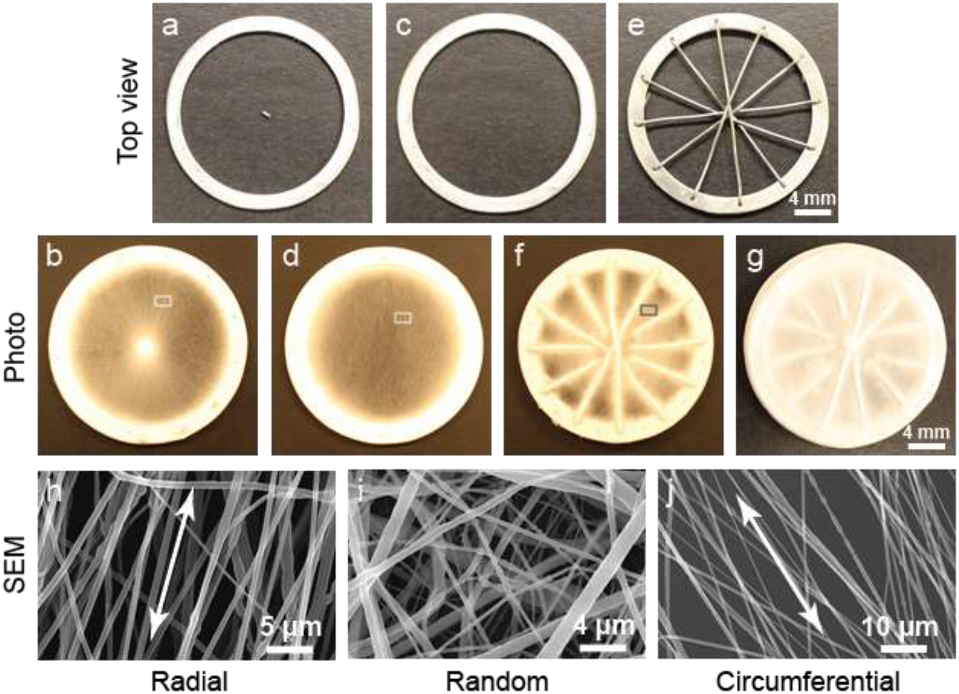
Fabrication and characterization of a TN substrate. Collector (a) used to fabricate radially oriented nanofibers (b). Collector (c) used to fabricate randomly oriented nanofibers (d). Collector (d) used to fabricate circumferentially oriented nanofibers (f). (g) Three layers were deposited one after another to prepare a TN substrate. (h) SEM image of oriented nanofibers in a radial substrate (b) indicated by a small rectangular region. (i) SEM image of nanofibers in a random substrate (d) indicated by a small rectangular region. (j) SEM image of oriented nanofibers in a circumferential substrate (f) indicated by a small rectangular region.
Scanning electron microscopy (SEM) images of nanofibers and their orientations in the individual layers were analyzed (Figure 1h–j). Nanofibers were aligned in the radial and circumferential layers, and randomly oriented in the random layer of a TN substrate. Alignments are shown by double-headed arrows. To determine the relative degree of fiber alignment, fast Fourier transform (FFT) analysis on the SEM images of fibrous layers was performed based on conversion of fiber orientation distribution in the images into frequency space (Figure S1, upper panel, Supplementary section). The frequency pixels are mostly distributed along a line normal to the fiber orientation, which means fibers were aligned in the layers. Applying an oval-profile, the radial intensity was summed and plotted against the angle of acquisition (Figure S1, lower panel, Supplementary section). The fibers in circumferential layers had narrower peak than the fibers in the radial layers i.e. the fibers in the circumferential layers were more aligned compared to the fibers in the radial layers. The nanofibers in all layers had a diameter of ~ 370 nm. The average pore size in the layers was greater than 10 μm, the average size of cells and it was expected to have sufficient cell infiltration into the TN substrate upon implantation.
3.2. Mold development, sample preparation and implantation
A mold with an apparent closed trileaflet-shaped cavity was designed. It had a lower part (Figure 2a) and an upper part (Figure 2b) and together formed the mold with a closed trileaflet-shaped cavity (shown by an arrow, Figure 2c). The opening of the cavity at the cylindrical surface of the mold represents the basal junction between each leaflet and the aorta. Three pinand-hole systems at the commissure sites were included in the design to prevent any relative rotation between the parts. Using this design, a mold was printed from ABS polymer – a biocompatible and non-biodegradable material (Figure 2d). To prepare a test implant sample, a TN substrate was placed on the lower part of the mold to keep the substrate center aligned with the mold center. The upper part of the mold was then placed on the substrate and hole-pin systems were locked. A biocompatible suture string was entered into the axial hole of the mold and knots in the string were made at two sides to hold both parts together axially. Before implantation, blood was extracted from a rat in which the sample would be implanted and then injected into the substrate lying inside the mold cavity to induce cell migration into the substrate upon implantation (Figure 2e). In the figure, the sample is seen in an upside down condition to prevent dripping of injected blood from the mold-cavity before implantation. Two samples (n=2) were implanted in each rat (Figure S2, Supplementary section) and thus, a total of ten samples (n=10) were implanted in five rats (n=5) for two months.
Figure 2:
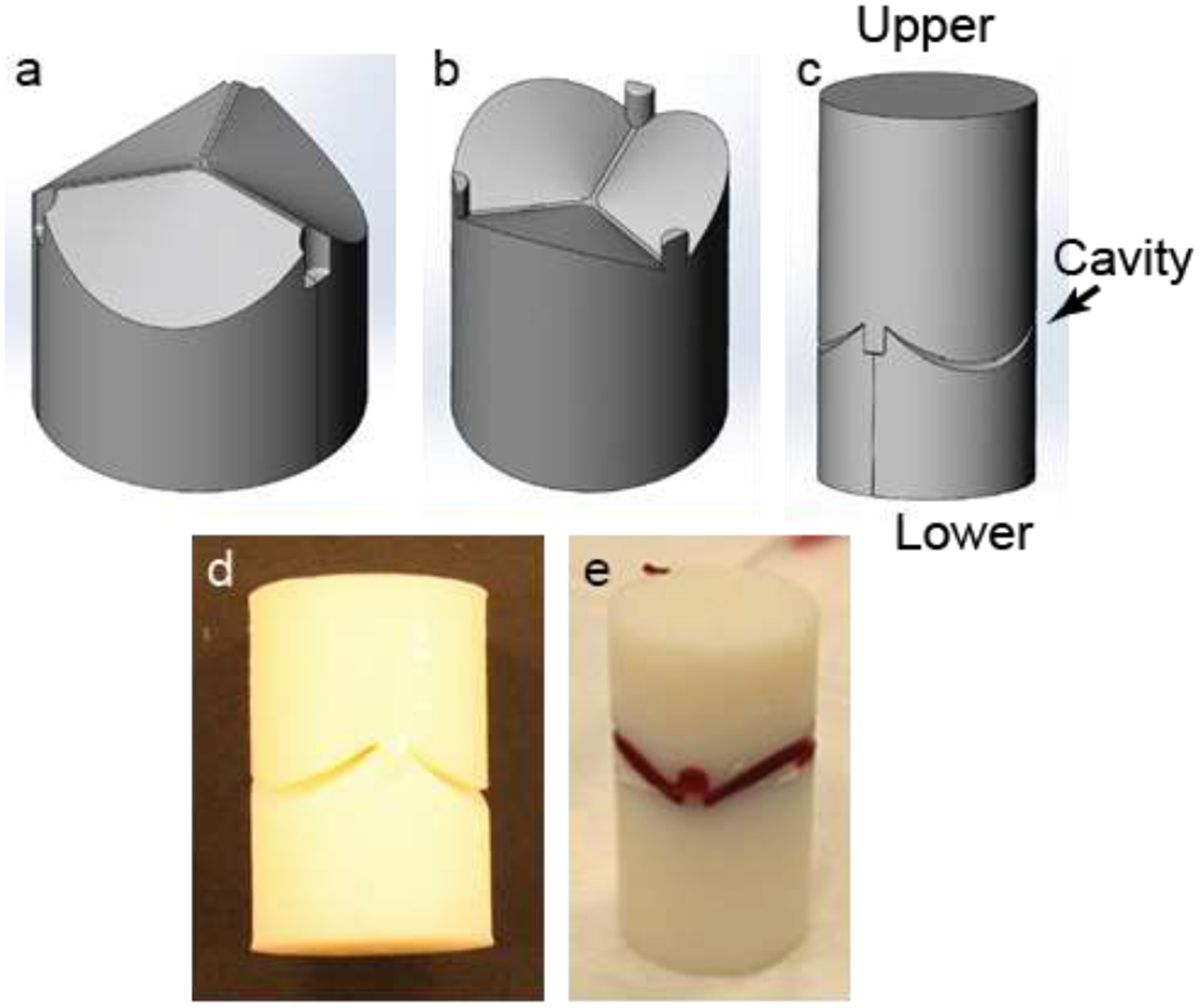
Mold used for substrate implantation. (a-c) Design of different mold parts. (d) A printed polymer-based mold with 18 mm diameter and 40 mm length. (e) A blood-stained substrate in a mold.
3.3. Explantation and morphology of the tissue constructs
After two months of implantation, the molds were explanted (Figure 3a). The developed tissue along the cylindrical surface of a mold was gently collected and used as a control tissue construct (CC) sample (Figure 3b). The collected CCs had no shape and were like a lump of tissue. The upper part of the mold was gently separated from the lower part and the tissue developed inside the mold cavity was collected and used as a test tissue construct (TC) sample (Figure 3c). From the figure, it seems that the TCs had a bowl shape; however, they had a closed trileaflet shape, which is not prominent in the figure. Nanofibrous spokes of TN substrates were clearly visible in the TCs. A total of ten CCs (n=10) and ten TCs (n=10) were collected and characterized.
Figure 3:
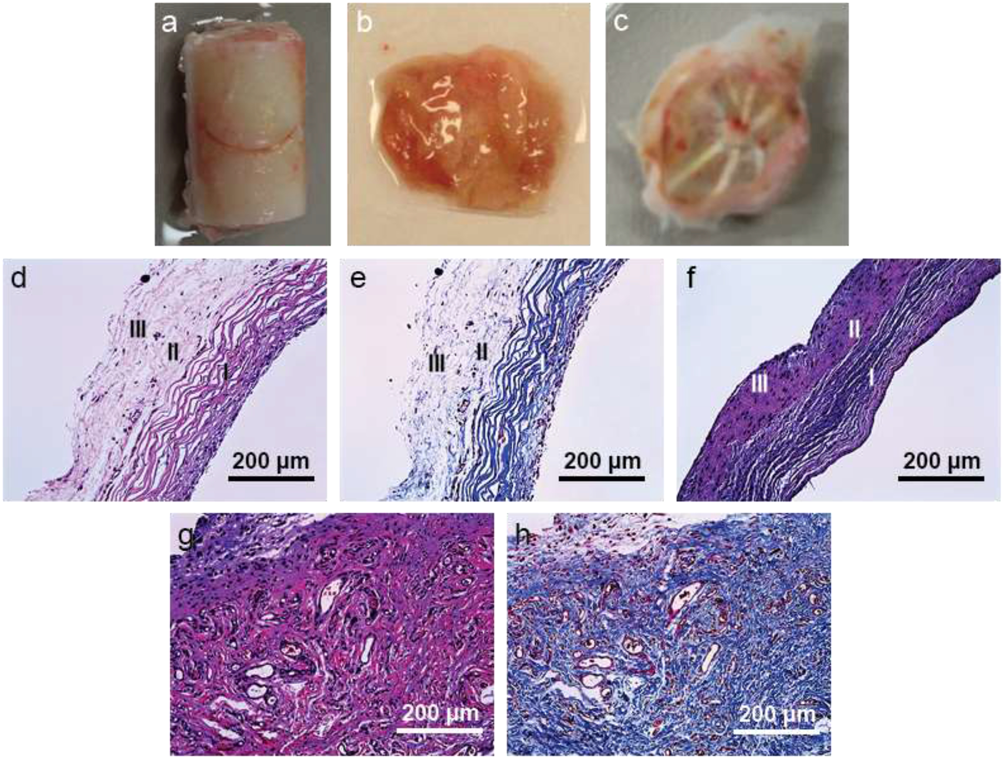
Explanted tissue and their morphological characterization. (a) Explanted tissue construct with a mold. (b) CC from the cylindrical surface of a mold. (c) TC from the mold cavity. (d) H&E stained image of a TC cross-sectionally. Staining shows presence of three layers – circumferential (I), random (II) and radial (III) layers in the construct. (e) Masson’s trichrome stained image of a TC cross-sectionally. Staining shows presence of three layers – circumferential (I), random (II) and radial (III) layers in the construct. (f) Masson’s trichrome stained image of a native valve leaflet cross-sectionally. There are three layer: circumferential (I), random (II) and radial (III) layers in the construct. (g) H&E stained image of a CC cross-sectionally. (h) Masson’s trichrome stained image of a CC cross-sectionally.
To examine the presence and orientations of the deposited extracellular matrix, especially collagen fibrils and cells in the TCs and CCs, constructs were stained histologically with hematoxylin and eosin (H&E) and Mason’s trichrome (MT) (Figure 3d–h). In the TCs, aligned circumferential layer (layer I) was distinctly visible (Figure 3d–e). Beyond this layer, random (layer II) and radial (layer III) layers could not be separated clearly. These two layers seemed less dense (in the images) compared to the circumferential layer because they were randomly and radially oriented (dots as alignment was perpendicular to the paper). To confirm the presence of three layers in the TCs, a native aortic valve leaflet from a pig was stained with MT (Figure 3f).
Morphologies of the TCs and the native leaflet sample were quite similar except the native leaflet tissue was more compact compared to the TCs. From now on, test tissue constructs are denoted as trilayered tissue constructs (TCs) due to presence of three layers. There were no particular orientations in the CCs (Figure 3g–h).
3.4. Tissue constructs analysis through TEM imaging
The orientation of deposited collagen fibrils in both CCs and TCs were examined further through transmission electron microscope (TEM). In the CCs, the collagen fibrils had no specific orientations (Figure 4a). The cells in the CCs also did not have any specific shape or orientation. Conversely, in the TCs, the collagen fibrils were oriented, possibly along the nanofibers of the TN substrates. The collagen fibrils in the TCs were circumferentially (Figure 4b), randomly (Figure 4c) and radially oriented (orientation is perpendicular to the paper) (Figure 4d) oriented in the respective three layers of the TCs. The cells in the TCs were also oriented along the circumferentially and radially oriented nanofibers.
Figure 4:
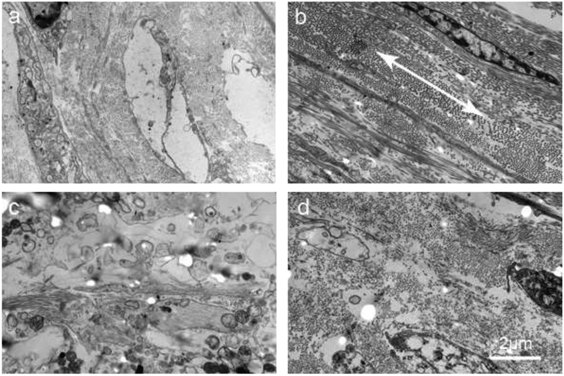
Transmission electron microscopy (TEM) images of tissue constructs. (a) TEM image of a CC cross-sectionally. (b) TEM image of the circumferential layer of a TC cross-sectionally. Double-headed arrow shows the direction of orientation. (c) TEM image of the random layer of a TC cross-sectionally. (d) TEM image of the radial layer of a TC cross-sectionally.
3.5. Tensile test
Tensile tests were performed on TN substrates, TCs and CCs to find the influence of nanofibers on tissue construct development. Tensile modulus of the TCs (2.24 ± 0.17 MPa) was almost 3 times higher than that of TN substrates (0.71 ± 0.13 MPa) and more than 1.5 times higher than that of CCs (1.37 ± 0.48) (Figure 5). Similarly, ultimate tensile strength (yield stress) of the TCs (0.53 ± 0.06 MPa) was higher than that of both TN substrates (0.43 ± 0.10 MPa) and CCs (0.36 ± 0.05 MPa). Orientation of the cells and their deposited ECM materials due to presence of oriented nanofibers in the TN substrates was certainly the cause of significantly higher tensile properties of TCs compared to that of CCs. In radial direction, tensile properties were not measured due to presence of nanofibrous spokes in radial direction which would prohibit in obtaining the actual tensile properties of only trilayered part in radial direction (Figure 1g and 3C). The tensile modulus and ultimate tensile strength (yield stress) of native heart valve leaflets in circumferential direction are ~ 7 MPa and 3.5 MPa, respectively [10], which are much higher than that of TCs in that direction.
Figure 5:
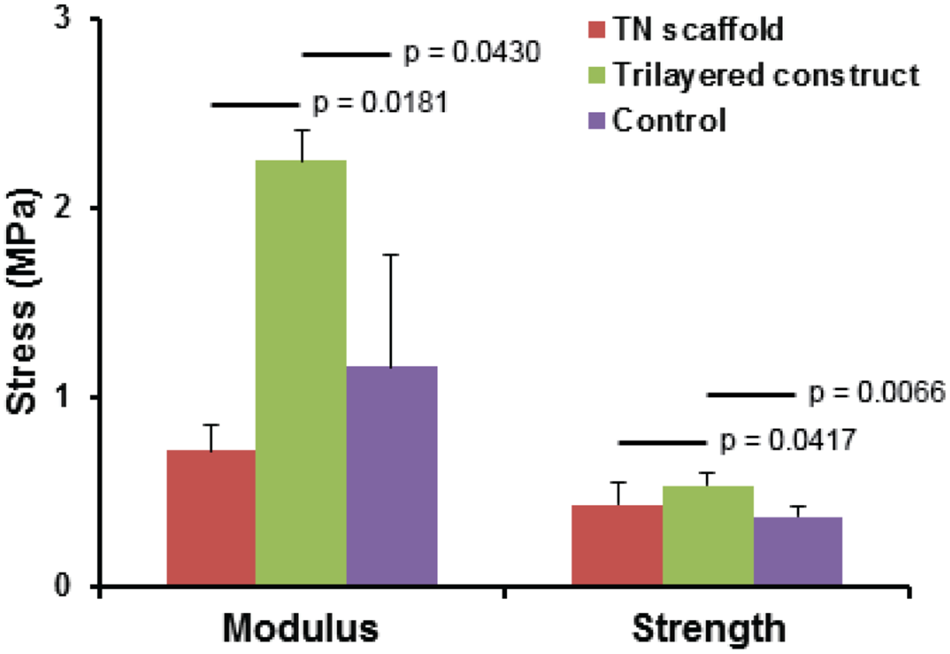
Tensile properties (modulus and ultimate strength) of TNs and TCs in their circumferential direction and of CCs.
3.6. Gene expression of infiltrated cells and their immunostaining
Vimentin and smooth muscle actin (α-SMA) markers are generally used to assess the phenotype(s) of valvular interstitial cells that reside in native valve leaflets [27, 28]. These markers were used to evaluate the gene expression of infiltrated cells in the TCs and CCs through real-time PCR. Infiltrated cells in CCs showed higher vimentin and α-SMA expression than in TCs (Figure 6a). In addition to these two markers, type-1 collagen expression of the cells in both tissue constructs was evaluated and similar results were observed. To find their protein expression, immunohistochemistry staining with vimentin and α-SMA antibody markers was performed. Presence of vimentin-expressed cells in both tissue constructs was greater than presence of α-SMA-expressed cells (Figure 6b–e). Both vimentin and α-SMA expression in circumferential layer was greater than that in other two layers in TCs.
Figure 6:
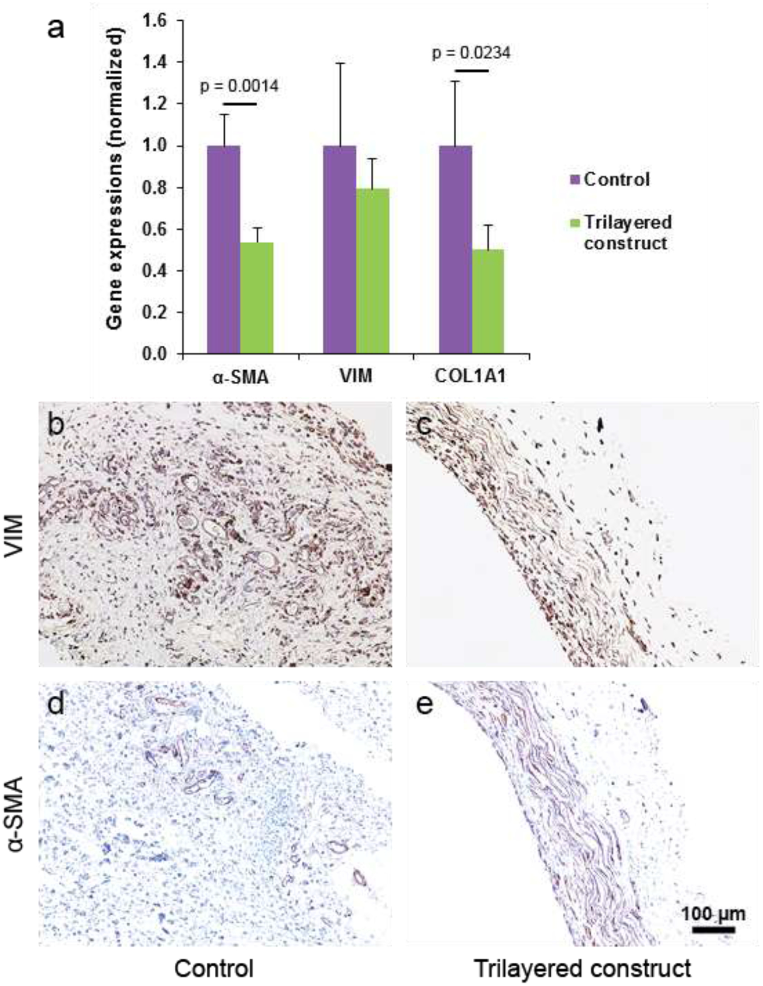
Gene expression analysis and immunohistochemical (IHC) staining of tissue constructs. (a) Gene expression of vimentin, α-SMA and type-I collagen markers in the cells present in the tissue constructs. (b-c) Images of CCs and TCs cross-sectionally from IHC staining with vimentin marker. (d-e) Images of CCs and TCs cross-sectionally from IHC staining with α-SMA marker.
3.7. Protein quantitation of tissue constructs and their histological and immunostaining
Presence of collagen, glycosaminoglycans (GAG) and elastin is important for the tissue constructs to function as a valve leaflet [29, 30]. Hence, quantitative measurements were done and compared with that of porcine native leaflets (Figure 7a). Deposited collagen in TCs and CCs were quite similar but less than that in native leaflets. Elastin deposition in TCs was higher than that in CCs but lower than that in native leaflets. Deposition of GAG in TCs was lower than that in both CCs and native leaflets.
Figure 7:
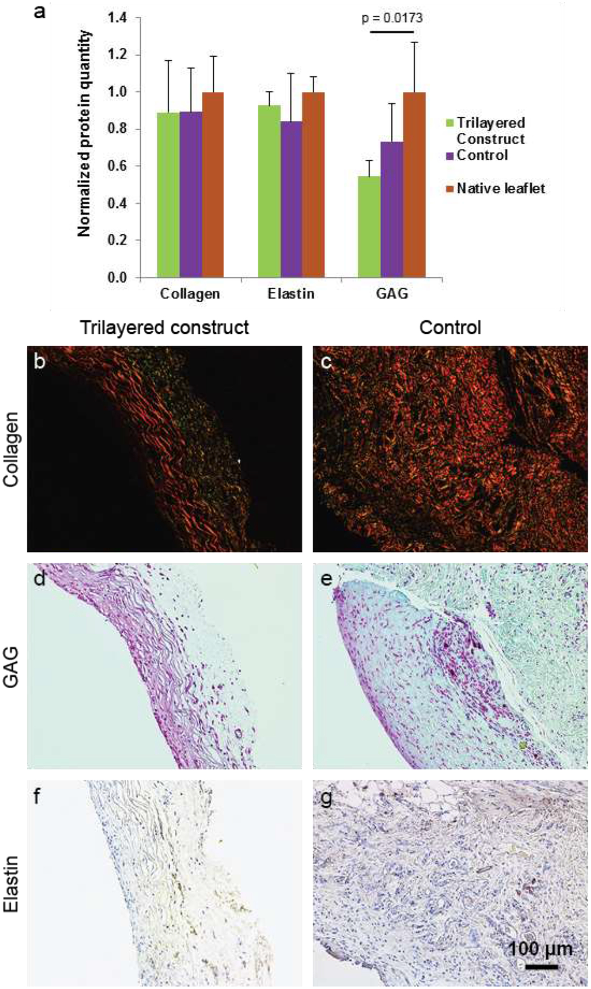
Histological and immunohistochemical (IHC) staining of both TCs and CCs for assay on ECM. (a) Quantification graph of those ECM materials present in both TCs, CCs and porcine native valve leaflets. (b-c) For collagen assay, the tissue were stained with picrosirius red and imaged in polarized light. (d-e) For GAG assay, tissues were stained with Safranin O. (f-g) IHC staining of tissue with elastin marker was performed for elastin assay. Quantification graph of those ECM materials present in TCs, CCs and porcine native valve leaflets.
A staining method was used to further assay their presence in the TCs and CCs. Tissue constructs stained with picrosirius red were imaged in polarized light to see the existence of collagen fibrils in tissue samples. In the TCs, color of collagen in the circumferential layer was reddish yellow, suggesting mature collagen, and that in the other two layers was mainly greenish yellow, suggesting less mature collagen (Figure 7b–c)[31]. Collagen in CCs was reddish yellow, suggesting mature collagen throughout the tissues.
Presence of GAG in the tissue constructs was assayed by staining them with Safranin O. More GAG was present in the circumferential layer than in the other two layers in TCs. GAG was present throughout CCs (Figure 7d–e). Similarly, presence of elastin was assayed by immunostaining tissue samples with elastin marker. Visually, presence of elastin in both TCs and CCs was much less than the presence of either collagen or GAG in those samples (Figure 7f–g).
4. Discussion
In heart valve tissue engineering, development of a functional leaflet tissue construct has prerogative for several reasons. First, heart valve diseases are mainly considered as diseases in the leaflets. Second, without an appropriate leaflet structure, the tissue construct may face retraction because the residing valvular interstitial cells in a native valve leaflet are sensitive to the morphology and structure of the leaflet. Third, a native leaflet has three diversely oriented layers — circumferentially, randomly and radially oriented fibrosa, spongiosa and ventricularis layers, respectively; mimicking this structure into a tissue construct is difficult [10, 12, 13]. In this study, a flat TN substrate mimicking the orientations of a native leaflet was prepared and used for in-vivo tissue engineering to assay the influence of oriented nanofibers on the development of a tissue structure, including orientation of infiltrated cells and their deposited ECM materials.
In our previous study, we performed in-vitro tissue engineering by seeding porcine valvular interstitial cells on flat TN substrates and observed positive outcomes [14]. However, for neotissue generation — especially generation of autologous neo-leaflet tissues that need to withstand systemic pressure — in-vivo tissue engineering is much more efficient than in-vitro tissue engineering[9]. Thus, in this study, we tried to develop tissue constructs through in-vivo tissue engineering by implanting the TN substrates subcutaneously in a rat model for two months.
Our current flat TN substrate cannot be modified to a perfect leaflet-shaped substrate, so we tried to give it a closed trileaflet shape (Figure 2a–b). To achieve it, molds with a closed trileaflet-shaped cavity were fabricated and the molds with a TN substrate inside the cavity were implanted subcutaneously in a rat model for in vivo tissue engineering. The explanted tissue-engineered constructs appeared to have a bowl shape, but minute observation revealed a closed trileaflet shape. Conversely, CCs had no shape. Thus, it can be interpreted that TCs had a closed trileaflet shape due to closed trileaflet shape of the substrates. As there were no constraints on the cells during in-vivo tissue engineering, there was no or very little retraction of the TCs after their release from the mold cavities [12, 13]. Thus, it is clear that to produce a perfect leaflet-shaped tissue construct, both the substrate and the mold cavity should have the leaflet shape so that the residing cells in the developing tissue construct do not face any constraints.
In the H&E- and MT-stained images, a trilayered structure with appropriate orientations was observed (Figure 3). TEM images of the constructs confirmed these orientations further (Figure 4). After implantation, the cells infiltrated into the substrates and aligned themselves along the nanofibers in each layer of the substrates; thus, their deposited ECM components were aligned along the nanofibers [32]. Alignment of cells and their deposited ECM materials are important for efficient function of a leaflet tissue construct. In previous research, constraints were used during in-vitro tissue engineering for the alignment of cells and their deposited ECM components [33, 34]. Unfortunately, after removal of constraints at the end of tissue development, the constructs showed retraction. In our tissue engineering method, cells infiltrated into the substrates and aligned themselves along the nanofibers so there were no constraints on the cells.
In clinical application, tissue-engineered leaflets in a heart valve should bear native pressure load (120/80 mm of Hg =16/11 kPa) [35]. Native valve leaflets with their tensile modulus of ~7 MPa bear this pressure load [10]. However, engineered leaflets with tensile modulus of ~ 3.49 MPa (circumferentially) have performed well in a heart valve replacement investigation in an animal model and showed improvement of their mechanical properties with cell infiltration and deposition of ECM materials [36, 37]. TCs developed in this study had a tensile modulus of ~ 2.24 MPa in circumferential direction, which is lower than that in previously applied engineered leaflets (~ 3.49 MPa). At this time, it is not known whether these TCs would be able to bear the physiological load. However, in our previous study, TN substrates in a fully closed state survived more than 70,000 cycles in an accelerated wear testing (AWT) system (frequency > 15 Hz) under dynamic physiologic load (120/80 mm of Hg) [14]. As the tensile properties of the TCs were higher than that of the TN substrates, it can be expected that the TCs would survive more cycles in this AWT system compared to the TN substrates. The TCs were not as compact as native valve leaflets (Figure 3e–f). Therefore, their mechanical properties can be improved by increasing compactness in two possible ways: 1) increasing the current implantation time period (2 months) and 2) implanting the substrates with only one part (either upper or lower) of the mold for two months, to increase the exposure of the substrates to in-vivo environment. In both cases, number of infiltrated cells in the substrates would be greater compared to findings in current study and more ECM materials would be deposited leading to more compactness of the tissue constructs. In our future study, the TN substrates should not have any nanofibrous spokes, so tensile properties of the TCs in radial direction can be measured. Further, the substrates will have leaflet shape instead of flat shape and their tensile properties in circumferential and radial directions will be similar to that of native leaflets. Our previous experience says that through in-vivo (subcutaneous) tissue engineering, neotissues cannot achieve tensile properties comparable to that of native leaflets with a limited period (2–3 months) but their tensile properties would be sufficient (modulus > 4 MPa) for heart valve replacement. After heart valve replacement with these neotissues, their mechanical properties will improve over time with cell infiltration and deposition of ECM materials and will be similar to that of native leaflets ultimately [36, 37].
Phenotype of residing cells in a tissue construct depicts different states of the construct including growing/remodeling state, quiescent state and diseased/damaged state [38]. In a native valve leaflet, the residing VICs show either quiescent fibroblast (vimentin) or active myofibroblast (vimentin and α-SMA) phenotype [27, 28]. Myofibroblast phenotype is related to non-quiescent states of a tissue, i.e., growing/remodeling state, diseased state and state due to the change in normal physiological environment surrounding the tissue [27, 28]. To determine the state of the tissue constructs, phenotype of cells in the constructs was examined through gene expression. Both CCs and TCs showed α-SMA expression (Figure 6a), which meant both tissue constructs were in growing state. Higher α-SMA expression in CCs compared to that in TCs seems to indicate that the molds resisted tissue growth. As substrates were placed in mold cavities, they were not completely (or directly) exposed to the in-vivo physiological environment; conversely, tissues grown on cylindrical surfaces of the molds were completely exposed to the in-vivo physiological environment. As the TCs were in growing state, more implantation time beyond two months would increase the compactness of the constructs leading to further improvement of their mechanical and biological properties. Vimentin and Col1A1 expression followed the pattern of α-SMA expression, possibly for the same reasons. Stained images of the constructs with vimentin and α-SMA antibody-markers showed the presence of vimentin and α-SMA protein signals (Figure 6b–e).
Histological and immunohistochemical staining images of the constructs showed the presence of collagen, glycosaminoglycans and elastin (Figure 7). Quantification study of these ECM materials showed that their relative quantities in TCs and native leaflets had no significant differences (Figure 7a). Previous research reports suggest that cellular adhesion to substrates and their interaction with substrates are affected by substrate morphology and its mechanical properties, which in turn influence ECM materials deposition [39, 40]. Quantitative comparison of the gene expression and deposited ECM materials seems to indicate that during the intermediate time of 2 months, cells in TCs were more active than those in CCs, leading to deposition of more ECM materials in TCs, and later, less cell activity in TCs. If these TCs are implanted as leaflets in a heart valve, it is expected that further cell infiltration (blood-borne cells and cells from sinus/aorta)into the constructs would occur. Cells would align themselves and deposit ECM materials further inside the constructs, leading to improvement of their functional efficiency [36, 41]. Notably, fiber orientations in the substrates could not influence production of any layer-specific protein deposition, i.e., collagen in circumferential layer, GAG in random layer and elastin in radial layer, which exists in a native leaflet. Possibly, a dynamic physiological flow environment is required for layer-specific protein deposition [42].
The developed TCs had a crucial positive outcome: three layers with native orientations — the aim of this study. However, for any real application they face several limitations: they did not have a perfect leaflet shape, they had fibrous spokes and their mechanical properties were lower than that of a native leaflet. These limitations can be resolved by appropriate designing of the trilayered substrate. Thus, considering the positive outcome obtained in this study, it is possible to develop an autologous native leaflet-shaped trilayered construct that can be used to generate a heart valve for heart valve replacement, which is our future goal.
5. Conclusion
By applying electrospinning technique, we prepared a TN substrate mimicking the orientations of three layers of a native valve leaflet. The substrate was placed inside a closed trileaflet-shaped cavity in a mold and then implanted subcutaneously in a rat model for in-vivo tissue engineering of a tissue construct. The construct was characterized morphologically, mechanically and biologically. The construct had a trilayered structure mimicking the orientations of three layers of a native valve leaflet. Nanofibers present in the substrate influenced the mechanical properties of the tissue construct. Different ECM components including collagen, glycosaminoglycans and elastin deposited in the tissue construct were quite equivalent quantitatively to that in a native leaflet. Outcomes of this study indicate that it is possible to develop a leaflet-shaped functional tissue construct.
Supplementary Material
Acknowledgment
This work is supported by the HH Sheikh Hamed bin Zayed Al Nahyan Program in Biological Valve Engineering and the National Institutes of Health (NIH #K99HL134823, NIH# R00HL134823).
Footnotes
Disclosure
None
References
- [1].Rayner J, Coffey S, Newton J, Prendergast BD. Aortic valve disease. International journal of clinical practice. 2014. [DOI] [PubMed] [Google Scholar]
- [2].Nkomo VT, Gardin JM, Skelton TN, Gottdiener JS, Scott CG, Enriquez-Sarano M. Burden of valvular heart diseases: a population-based study. Lancet. 2006;368:1005–11. [DOI] [PubMed] [Google Scholar]
- [3].Tillquist MN, Maddox TM. Cardiac crossroads: deciding between mechanical or bioprosthetic heart valve replacement. Patient Preference and Adherence. 2011;5:91–9. [DOI] [PMC free article] [PubMed] [Google Scholar]
- [4].Rabkin-Aikawa E, Mayer JE Jr., Schoen FJ. Heart valve regeneration. Advances in biochemical engineering/biotechnology. 2005;94:141–79. [DOI] [PubMed] [Google Scholar]
- [5].Harris C, Croce B, Cao C. Tissue and mechanical heart valves. Annals of cardiothoracic surgery. 2015;4:399-. [DOI] [PMC free article] [PubMed] [Google Scholar]
- [6].Mirnajafi A, Zubiate B, Sacks MS. Effects of cyclic flexural fatigue on porcine bioprosthetic heart valve heterograft biomaterials. ournal of Biomedical Materials Research Part A. 2010;94A:205–13. [DOI] [PMC free article] [PubMed] [Google Scholar]
- [7].Manji RA, Zhu LF, Nijjar NK, Rayner DC, Korbutt GS, Churchill TA, et al. Glutaraldehydefixed bioprosthetic heart valve conduits calcify and fail from xenograft rejection. Circulation. 2006;114:318–27. [DOI] [PubMed] [Google Scholar]
- [8].VeDepo MC, Detamore MS, Hopkins RA, Converse GL. Recellularization of decellularized heart valves: Progress toward the tissue-engineered heart valve. Journal of tissue engineering. 2017;8:2041731417726327. [DOI] [PMC free article] [PubMed] [Google Scholar]
- [9].Nakayama Y, Takewa Y, Sumikura H, Yamanami M, Matsui Y, Oie T, et al. In-body tissue-engineered aortic valve (Biovalve type VII) architecture based on 3D printer molding. J Biomed Mater Res B Appl Biomater. 2015;103:1–11. [DOI] [PubMed] [Google Scholar]
- [10].Masoumi N, Annabi N, Assmann A, Larson BL, Hjortnaes J, Alemdar N, et al. Tri-layered elastomeric scaffolds for engineering heart valve leaflets. Biomaterials. 2014;35:7774–85. [DOI] [PMC free article] [PubMed] [Google Scholar]
- [11].Jana S, Simari RD, Spoon DB, Lerman A. Drug delivery in aortic valve tissue engineering. J Control Release. 2014;196:307–23. [DOI] [PubMed] [Google Scholar]
- [12].van Loosdregt IA, Argento G, Driessen-Mol A, Oomens CW, Baaijens FP. Cell-mediated retraction versus hemodynamic loading - A delicate balance in tissue-engineered heart valves. J Biomech. 2014;47:2064–9. [DOI] [PubMed] [Google Scholar]
- [13].van Vlimmeren MA, Driessen-Mol A, Oomens CW, Baaijens FP. Passive and active contributions to generated force and retraction in heart valve tissue engineering. Biomech Model Mechanobiol. 2012;11:1015–27. [DOI] [PubMed] [Google Scholar]
- [14].Jana S, Lerman A. Behavior of valvular interstitial cells on trilayered nanofibrous substrate mimicking morphologies of heart valve leaflet. Acta Biomater. 2019;85:142–56. [DOI] [PMC free article] [PubMed] [Google Scholar]
- [15].Tseng H, Puperi DS, Kim EJ, Ayoub S, Shah JV, Cuchiara ML, et al. Anisotropic poly(ethylene glycol)/polycaprolactone hydrogel-fiber composites for heart valve tissue engineering. Tissue Eng Part A. 2014;20:2634–45. [DOI] [PMC free article] [PubMed] [Google Scholar]
- [16].Masoumi N, Larson BL, Annabi N, Kharaziha M, Zamanian B, Shapero KS, et al. Electrospun PGS:PCL Microfibers Align Human Valvular Interstitial Cells and Provide Tunable Scaffold Anisotropy. Adv Healthc Mater. 2014;3:929–39. [DOI] [PMC free article] [PubMed] [Google Scholar]
- [17].Cooper A, Jana S, Bhattarai N, Zhang M. Aligned chitosan-based nanofibers for enhanced myogenesis. Journal of Materials Chemistry. 2010;20:8904–11. [Google Scholar]
- [18].Kievit FM, Cooper A, Jana S, Leung MC, Wang K, Edmondson D, et al. Aligned chitosanpolycaprolactone polyblend nanofibers promote the migration of glioblastoma cells. Advanced Healthcare Materials. 2013;2:1651–9. [DOI] [PMC free article] [PubMed] [Google Scholar]
- [19].Leung M, Cooper A, Jana S, Tsao CT, Petrie TA, Zhang M. Nanofiber-based in vitro system for high myogenic differentiation of human embryonic stem cells. Biomacromolecules. 2013;14:4207–16. [DOI] [PubMed] [Google Scholar]
- [20].Woodruff MA, Hutmacher DW. The return of a forgotten polymer—Polycaprolactone in the 21st century. Progress in Polymer Science. 2010;35:1217–56. [Google Scholar]
- [21].Jana S, Lerman A, Simari RD. In Vitro Model of a Fibrosa Layer of a Heart Valve. ACS Appl Mater Interfaces. 2015;7:20012–20. [DOI] [PubMed] [Google Scholar]
- [22].Edmondson D, Cooper A, Jana S, Wood D, Zhang M. Centrifugal electrospinning of highly aligned polymer nanofibers over a large area. Journal of Materials Chemistry. 2012;22:18646–52. [Google Scholar]
- [23].Jana S, Zhang M. Fabrication of 3D aligned nanofibrous tubes by direct electrospinning. Journal of Materials Chemistry B. 2013;1:2575–81. [DOI] [PubMed] [Google Scholar]
- [24].Jana S, Lerman A. Effect of an underlying substrate in a nanofibrous membrane system on cultured cells. Biomedical Physics & Engineering Express. 2016;2:045001(1–13). [Google Scholar]
- [25].Jana S, Hennessy R, Franchi F, Young M, Hennessy R, Lerman A. Regeneration ability of valvular interstitial cells from diseased heart valve leaflets. RSC Advances. 2016;6:113859–70. [Google Scholar]
- [26].Khorramirouz R, Go JL, Noble C, Jana S, Maxson E, Lerman A, et al. A novel surgical technique for a rat subcutaneous implantation of a tissue engineered scaffold. Acta histochemica. 2018;120:282–91. [DOI] [PMC free article] [PubMed] [Google Scholar]
- [27].Wang H, Leinwand LA, Anseth KS. Cardiac valve cells and their microenvironment--insights from in vitro studies. Nature reviews Cardiology. 2014;11:715–27. [DOI] [PMC free article] [PubMed] [Google Scholar]
- [28].Wang H, Tibbitt MW, Langer SJ, Leinwand LA, Anseth KS. Hydrogels preserve native phenotypes of valvular fibroblasts through an elasticity-regulated PI3K/AKT pathway. Proc Natl Acad Sci U S A. 2013;110:19336–41. [DOI] [PMC free article] [PubMed] [Google Scholar]
- [29].Misfeld M, Sievers HH. Heart valve macro- and microstructure. Philosophical transactions of the Royal Society of London Series B, Biological sciences. 2007;362:1421–36. [DOI] [PMC free article] [PubMed] [Google Scholar]
- [30].Hinton RB, Yutzey KE. Heart valve structure and function in development and disease. Annual review of physiology. 2011;73:29–46. [DOI] [PMC free article] [PubMed] [Google Scholar]
- [31].Patel B, Xu Z, Pinnock CB, Kabbani LS, Lam MT. Self-assembled Collagen-Fibrin Hydrogel Reinforces Tissue Engineered Adventitia Vessels Seeded with Human Fibroblasts. Scientific reports. 2018;8:3294-. [DOI] [PMC free article] [PubMed] [Google Scholar]
- [32].Jana S, Levengood SKL, Zhang M. Anisotropic Materials for Skeletal-Muscle-Tissue Engineering. Advanced materials (Deerfield Beach, Fla). 2016;28:10588–612. [DOI] [PMC free article] [PubMed] [Google Scholar]
- [33].Mol A, Driessen NJB, Rutten MCM, Hoerstrup SP, Bouten CVC, Baaijens FPT. Tissue engineering of human heart valve leaflets: A novel bioreactor for a strain-based conditioning approach. Annals of Biomedical Engineering. 2005;33:1778–88. [DOI] [PubMed] [Google Scholar]
- [34].Neidert MR, Tranquillo RT. Tissue-engineered valves with commissural alignment. Tissue Engineering. 2006;12:891–903. [DOI] [PubMed] [Google Scholar]
- [35].Balachandran K, Sucosky P, Yoganathan AP. Hemodynamics and mechanobiology of aortic valve inflammation and calcification. International journal of inflammation. 2011;2011:263870. [DOI] [PMC free article] [PubMed] [Google Scholar]
- [36].Syedain ZH, Bradee AR, Kren S, Taylor DA, Tranquillo RT. Decellularized tissue-engineered heart valve leaflets with recellularization potential. Tissue Eng Part A. 2013;19:75969. [DOI] [PMC free article] [PubMed] [Google Scholar]
- [37].Syedain ZH, Meier LA, Reimer JM, Tranquillo RT. Tubular heart valves from decellularized engineered tissue. Ann Biomed Eng. 2013;41:2645–54. [DOI] [PMC free article] [PubMed] [Google Scholar]
- [38].Orgogozo V, Morizot B, Martin A. The differential view of genotype-phenotype relationships. Frontiers in genetics. 2015;6:179-. [DOI] [PMC free article] [PubMed] [Google Scholar]
- [39].Hinderer S, Seifert J, Votteler M, Shen N, Rheinlaender J, Schaffer TE, et al. Engineering of a bio-functionalized hybrid off-the-shelf heart valve. Biomaterials. 2014;35:2130–9. [DOI] [PubMed] [Google Scholar]
- [40].Kolewe ME, Park H, Gray C, Ye X, Langer R, Freed LE. 3D structural patterns in scalable, elastomeric scaffolds guide engineered tissue architecture. Advanced materials (Deerfield Beach, Fla). 2013;25:4459–65. [DOI] [PMC free article] [PubMed] [Google Scholar]
- [41].Serruys PW, Fau Miyazaki Y- Fau Katsikis A, Katsikis A- Fau Abdelghani M, Abdelghani M- Fau Leon MB, Leon Mb- Fau Virmani R, Virmani R- Carrel T, et al. Restorative valve therapy by endogenous tissue restoration: tomorrow’s world? Reflection on the EuroPCR 2017. session on endogenous tissue restoration. [DOI] [PubMed] [Google Scholar]
- [42].Combs MD, Yutzey KE. Heart Valve Development Regulatory Networks in Development and Disease. Circulation Research. 2009;105:408–21. [DOI] [PMC free article] [PubMed] [Google Scholar]
Associated Data
This section collects any data citations, data availability statements, or supplementary materials included in this article.