Abstract
Background
Lewinnek’s recommendation for orienting the cup in THA is criticized because it involves a static assessment of the safe zone and because it does not consider stem geometry. A revised concept of the safe zone should consider those factors, but to our knowledge, this has not been assessed.
Questions/purposes
(1) To determine the shape, size, and location of target zones for combined cup and stem orientation for a straight stem/hemispheric cup THA to maximize the impingement-free ROM and (2) To determine whether and how these implant positions change as stem anteversion, neck-shaft angle, prosthetic head size and target range of movements are varied.
Methods
A three-dimensional computer-assisted design model, in which design geometry was expressed in terms of parameters, of a straight stem/hemispheric cup hip prosthesis was designed, its design parameters modified systematically, and each prosthesis model was implanted virtually at predefined component orientations. Functional component orientation referencing to body planes was used: cups were abducted from 20° to 70°, and anteverted from -10° to 40°. Stems were rotated from -10° to 40° anteversion, neck-shaft angles varied from 115° to 143°, and head sizes varied from 28 to 40 mm. Hip movements up to the point of prosthetic impingement were tested, including simple flexion/extension, internal/external rotation, ab/adduction, combinations of these, and activities of daily living that were known to trigger dislocation. For each combination of parameters, the impingement-free combined target zone was determined. Maximizing the size of the combined target zone was the optimization criterion.
Results
The combined target zones for impingement-free cup orientation had polygonal boundaries. Their size and position in the diagram changed with stem anteversion, neck-shaft angle, head size, and target ROM. The largest target zones were at neck-shaft angles from 125° to 127°, at stem anteversions from 10° to 20°, and at radiographic cup anteversions between 17° and 25°. Cup anteversion and stem anteversion were inverse-linearly correlated supporting the combined-anteversion concept. The range of impingement-free cup inclinations depended on head size, stem anteversion, and neck-shaft angle. For a 127°-neck-shaft angle, the lowest cup inclinations that fell within the target zone were 42° for the 28-mm and 35° for the 40-mm head. Cup anteversion and combined version depended on neck-shaft angle. For head size 32-mm cup, anteversion was 6° for a 115° neck-shaft angle and 25° for a 135°-neck-shaft angle, and combined version was 15° and 34° respectively.
Conclusions
The shape, size, and location of the combined target zones were dependent on design and implantation parameters of both components. Changing the prosthesis design or changing implantation parameters also changed the combined target zone. A maximized combined target zone was found. It is mandatory to consider both components to determine the accurate impingement-free prosthetic ROM in THA.
Clinical Relevance
This study accurately defines the hypothetical impingement-free, design-specific component orientation in THA. Transforming it into clinical precision may be the case for navigation and/or robotics, but this is speculative, and as of now, unproven.
Introduction
Correct cup and stem positioning is essential in THA; however, a consensus about the correct position of these components has not been reached and remains a subject of debate [10, 16, 24, 56, 72]. Lewinnek’s safe zone for cup positioning [50], which is based on radiographic and empiric data about dislocations, has been accepted for a long time, but it has been criticized more recently [1, 30, 73, 85]. Its critics raise at least two concerns. First, the original study showed that even THAs with cups positioned in the safe zone sometimes dislocated [1], and second, controlling the cup’s orientation alone appears to be insufficient [31], especially when solely referencing the anterior pelvic plane. Beyond that, a more-individual positioning regarding femoral anatomy, pelvic tilt, the spino-pelvic relationship, and the interplay between the cup and stem seem important to consider in a surgeon’s positioning strategy [1, 30, 72].
McKibbin [53] introduced the term combined version for assessing the growing dysplastic hips to combine acetabular and femoral neck versions (McKibbin’s index). Typically, high femoral anteversion and low acetabular anteversion or even retroversion develop in the hips of infants [93]. Later on, the combined version concept was introduced into THA [70] and quantified for a specific hip prosthesis [95].
More investigations about the functional positioning of both components applying three-dimensional (3-D) geometry and comprehensive kinematic analyses confirmed that the interplay between the cup and stem determines the functional prosthetic ROM [6, 26, 33, 39, 88, 99]. Although theoretical, these studies gave prosthesis-based directions on how to functionally position the cup and stem, not only to prevent dislocation or impingement but also to reduce the risk of complications such as wear, squeaking, as well as edge and peak loading [4, 27, 28, 52, 73, 91]. Functional referencing (relying on functional guidelines such as the functional pelvic plane or body planes), although less common, may be superior to morphologic referencing with respect to joint stability [89]. Nevertheless, morphologic referencing (referring to anatomic landmarks such as the anterior pelvic plane, transverse acetabular ligament [2, 10], iliac bone, and posterior femoral condyles) is in wide use clinically [5, 7, 23, 24, 74, 77, 90, 97, 100]. Changing the cup’s functional orientation without changing its morphologic orientation led to a higher dislocation rate in one study [8]. Identifying the body planes is necessary for functional referencing. This is a challenging task, although it is less difficult in patients in supine position and more difficult in patients in the lateral decubitus [76, 78].
Finding an accurate, functional, component orientation for an individual patient and a specific prosthesis requires a multifactorial approach. Our approach looks for design parameters and implantation orientations of the implants that enable impingement-free prosthetic joint motions as determined by activities of daily living [21, 46, 55, 66, 67] while considering anatomic restraints. Ideally, a prosthesis system should come with recommended prosthesis-specific (technical) targets provided by the distributor because the prosthesis’ design determines the kinematic performance of a prosthesis system. Then it would be at the surgeon’s discretion to adapt these targets to patient-specific factors, such as changes in pelvic tilt [3, 20, 26, 45, 48, 54, 61, 69, 74, 101], changes because of limitations in the lower spine [8, 13, 30, 32, 34, 38, 47, 62, 71, 79, 84], incidental pelvic reorientation after THA [11, 47, 51, 61, 68], and other changes after surgery [65, 83, 87]. However, to our knowledge, no prosthesis-specific targets have been published. We wished to demonstrate the technical feasibility of developing such targets for a hypothetical implant system, but one that uses implant geometry that is employed in common practice: a straight stem and a fully hemispherical acetabular shell.
We therefore sought (1) To determine the shape, size, and location of target zones for combined cup and stem orientation for a straight stem/hemispheric cup THA to maximize the impingement-free ROM and (2) To determine whether and how these implant positions change as stem anteversion, neck-shaft angle, prosthetic head size, and target range of movements are varied.
Materials and Methods
A kinematic analysis was performed using a 3-D geometric model of a total hip prosthesis consisting of a fully hemispherical acetabular shell, and a standard straight stem with a round, conically shaped neck. All relevant design parameters, such as the inner and outer diameter of the cup, head diameter, trunnion design, neck diameter and neck cross-sectional profile, head-to-neck ratio, orientation of the neck expressed by the neck-shaft angle and stem anteversion, cup radiographic anteversion, and cup radiographic inclination were used as parameters in the model. Thus, different straight stem designs were modeled and tested (Table 1). The model was created in Maple R16 Software (Maplesoft, Waterloo, Canada) for batch computation. Two algorithms were established: one was a collision detection algorithm that analyzed joint motion until primary impingement occurred, and the other was a more analytic algorithm that calculated compatible cup positions for predefined hip movements. The second algorithm was the computational representation of the target ROM concept, meaning that the target motion of the femur was preset, and cup orientations allowing this motion were calculated (Fig. 1A-B).
Table 1.
Tested design and implantation parameters
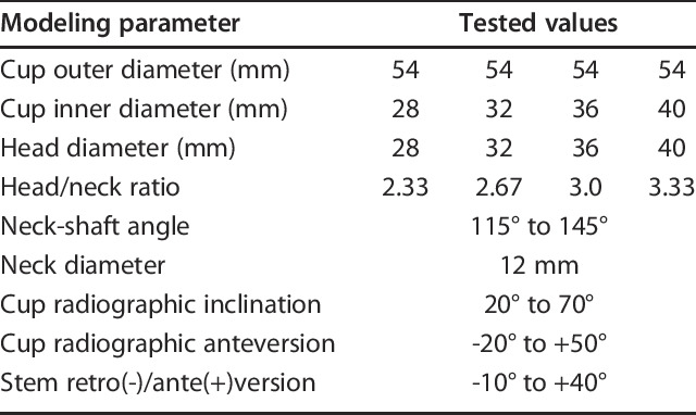
Fig. 1.
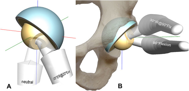
These images show prosthetic impingement in a combined extension/external rotation (A) and a flexion/internal rotation maneuver (B), viewed posterosuperiorly (A) and anterolaterally (B) (body axes: red = mediolateral, green = AP, blue = superioinferior, Flx = Flexion, Ext = Extension, IR = internal rotation, ER = external rotation)
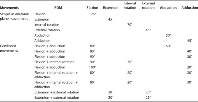
The analysis generated iso-lines that revealed zones for cup orientations compatible to these predefined stem target motions (Fig. 2). For example, the Flx125°-line divides the diagram in a lower-left and an upper-right region. The region on the upper-right of the Flx125°-line denotes all impingement-free cup positions at 125° hip flexion while on the lower-left all impinging cup positions are located. The region below the Ext30°-line denotes all impingement-free cup positions at 30° hip extension and so on. The intersecting combination of all these regions like in the set theory designated the combined target zone together with its polygonal boundary (Fig. 2). All cup orientations within this zone fulfilled all criteria to reach the predefined target ROMs (Table 2). Stem anteversion, head size and neck-shaft angle were the parameters of the diagram. We used Excel (Office 2016, Microsoft Corp, Redmond, WA, USA) to generate charts, means and SDs, correlations and regression analyses. Target zone sizes were calculated applying the formula for the area of irregular polygons (xi, yi are the coordinates of the polygons’ vertices, n is the number of vertices):
Fig. 2.
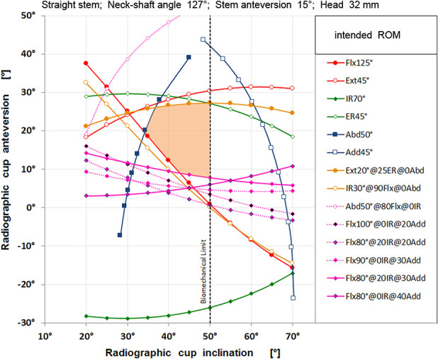
The red shaded area shows the combined target zone for a straight stem with a neck-shaft angle of 127°, stem anteversion of 15°, and head diameter of 32 mm. Cups oriented within this zone allowed all listed movements without prosthetic impingement. Cup inclination is limited to 50° for biomechanical reasons.
Table 2.
ROM tested
 Simple in-anatomic plane movements and also combined movements were analyzed. There was a focus on combined movements that are known to cause dislocation and are commonly used to test hip stability intraoperatively such as combined adduction + flexion + internal rotation and extension + external rotation [12, 58]. We also considered the ceiling effect due to bone-on-bone impingement for femoral heads of 32 mm or greater in flexion [18]. Nevertheless, these predefined hip movements were somewhat arbitrary and hence, they arbitrarily affected the shape and size of the combined target zone.
The radiographic definition was used for identifying the orientation of the acetabular components [57]. All orientations referred to the body planes: These are the coronal, sagittal, and axial planes that define the body’s coordinate system. In particular, the movements and the orientations of the cup and the stem were referenced to this body coordinate system [37].
A non-orthogonal coordinate system was applied to the hip according to the recommendations of the International Society of Biomechanics [36, 98]. All movements started in the neutral position. The mediolateral axis (the flexion/extension axis) was affixed to the pelvis while the AP-axis (the abduction/adduction axis) was the floating axis. This AP-axis rotated around the mediolateral axis during flexion and extension. The longitudinal axis of the leg was also floating and rotated with flexion and extension and adduction and abduction. The sitting position was defined like this: 80° femoroacetabular flexion and 10° posterior pelvic tilt resulting in a 90° angle between thigh and trunk [30].
A standard straight femoral stem was implanted keeping its shaft co-linear with the intramedullary axis of the proximal femur. Hence, the shaft axis was flexed 5° and adducted 5° with respect to the body planes. This axis served as the rotational axis for stem version. Tests were performed from -10° of retroversion to 40° of stem anteversion in 5° increments (the minus sign [-] denotes retroversion). The following cup orientations were tested: radiographic inclination from 20° to 70° and radiographic anteversion from -20° to 50° (the minus sign [-] denotes retroversion).
The neck-shaft angle varied from 115° to 143°, in 4° increments over the entire range and 2° increments between 119° and 139°. Head sizes were 28, 32, 36 and 40 mm. The slightly conically shaped round neck yielded head-to-neck ratios ranging from 2.3 for the 28-mm, 2.67 for the 32-mm, 3.0 for the 36-mm, to 3.33 for the 40-mm-head (Table 1).
To facilitate comparison the same chart layout as Lewinnek’s was used to visualize the combined target zone (Fig. 2). A total of 572 diagrams each containing 19 test movements and 121 tested component orientations were produced and analyzed.
The optimization process searched for the largest combined target zone as a function of radiographic cup anteversion, radiographic cup inclination, stem anteversion, neck-shaft angle, head size, and head-to-neck ratio. We chose this optimization criterion because it included the highest number of valid positioning combinations and offers the surgeon the highest flexibility for adjusting both components while still offering the patient the intended impingement-free ROM.
Additionally, the optimization process searched for the lowest cup inclination aiming at improved tribology and increased jumping distance for enhanced joint stability [63, 75]. Furthermore, combined version was calculated for neck-shaft angles from 115° to 143° using linear regression analysis.
Results
The shapes of the combined target zones for each stem anteversion were polygonal (Fig. 2). By rotating stem anteversion to -5° (meaning 5° retroversion) the size of the combined target zone was reduced, its contour changed, and the zone moved toward the top of the diagram (Fig. 3), whereas by increasing stem anteversion to 40° its size was also reduced, its contour also changed, but it moved into the opposite direction (Fig. 4). Taking each diagram of each stem anteversion and stacking all of them sequentially provided the 3-D target space (Fig. 5). The largest combined target zones were found for neck-shaft angles ranging from 122° to 130° with peaks at 125° to 127° (Fig. 6). Neck-shaft angles below 121° or above 131° provided smaller combined target zones. Larger prosthetic heads led to larger combined target zones, but the peak position remained at the 125° to 127° neck-shaft-angle corridor.
Fig. 3.
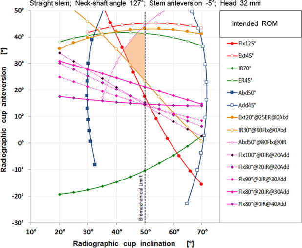
Putting the stem into -5° retroversion yielded other iso-lines and a smaller shaded combined target zone of a different shape which is located in the upper part of the diagram.
Fig. 4.
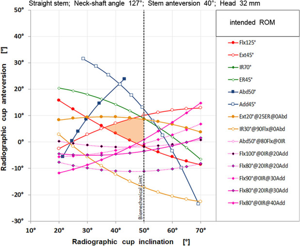
Putting the stem into 40° anteversion yielded other iso-lines and a smaller shaded combined target zone of a different shape which is located in the lower part of the diagram.
Fig. 5.
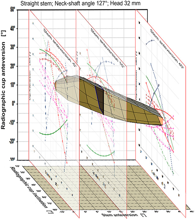
Stacking the two-dimensional graphs of all stem anteversions yielded a three-dimensional target space determining stem anteversion, cup anteversion, and inclination (2-D graphs for -5°-, 15°- and 40°-stem anteversion are displayed only, neck-shaft angle is 127°).
Fig. 6.
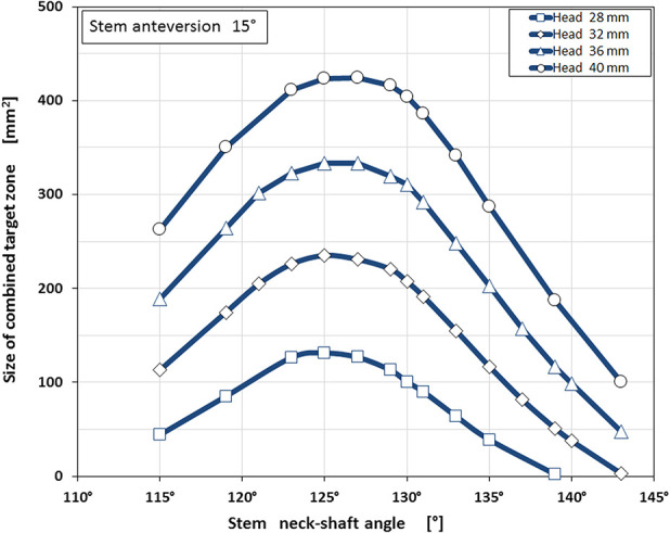
The size of the combined target zone was dependent on the neck-shaft angle. The largest zones were found for neck-shaft angles from 122° to 130° (head sizes from 28 mm to 40 mm, stem anteversion 15°).
Functional stem anteversions from 5° to 25° provided the largest combined target zones. This means that every stem version within this wide range fulfills the optimization criterion of maximizing the size of the combined target zone. (Fig. 7).
Fig. 7.
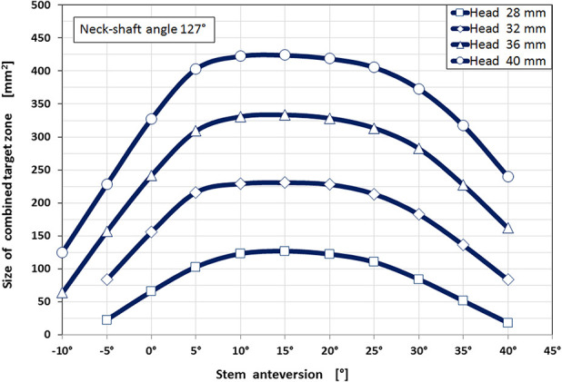
The largest combined target zones were found for stem anteversions from 5° to 25° for all head sizes from 28 mm to 40 mm.
Radiographic cup anteversions from 15° to 25° showed the largest combined target zones, with a relative sharp decline in the size of the combined target zone when the cup anteversion increased above 31° (Fig. 8). Cup anteversion also depended on the neck-shaft angle: Changing the neck-shaft angle required the cup anteversion to be adjusted to keep the hip in the target zone (Fig. 9). For example, a neck-shaft angle of 115° required 5° of cup anteversion, while a 135° neck-shaft angle required 25° of cup anteversion. Likewise, when substituting a lateralizing (more varus, 123°) stem for a 135° neck-shaft angle stem, the cup had to be reoriented from 18° to 25° anteversion to achieve the largest combined target zone.
Fig. 8.
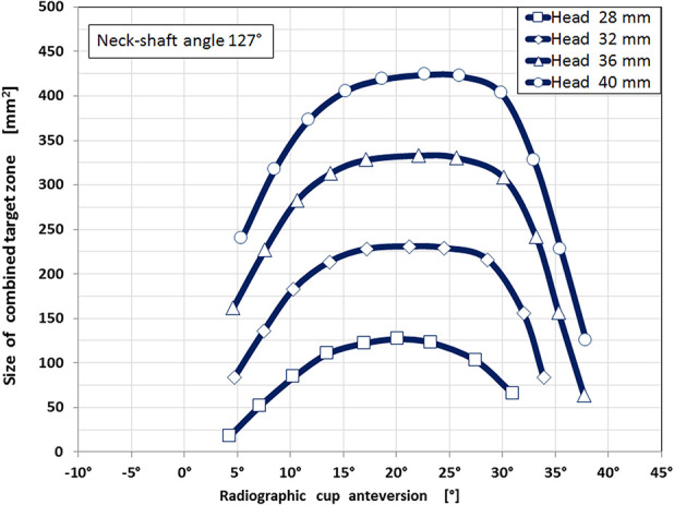
The largest combined target zones were found for radiographic cup anteversion from 15° to 29°. The size of the combined target zone was substantially smaller for cup anteversions below 11° and above 31°.
Fig. 9.
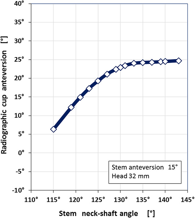
Cup anteversion was dependent on neck-shaft angle. Greater neck-shaft angles required greater cup anteversion. There was a ceiling effect showing an asymptotic leveling at 25° cup anteversion (head size 32 mm, stem anteversion 15°).
Cup inclination was not dependent on target zone size. Instead, cup inclination was sensitive to cup anteversion, neck-shaft angle, and head size. The lowest radiographic cup inclination was in stem anteversions between 15° and 25° (Fig. 10) and in neck-shaft angles from 125° to 130° (Fig. 11). Lowest cup inclinations were 42° for a 28-mm head, 40° for a 32-mm head, 37° for a 36-mm head, and 35° for a 40-mm head. The upper limit for cup inclination was intentionally set to 50° because cup positions more vertical than that are associated with other problems, in particular accelerated polyethylene wear, edge loading, and reduced jumping distance [19, 86, 92].
Fig. 10.
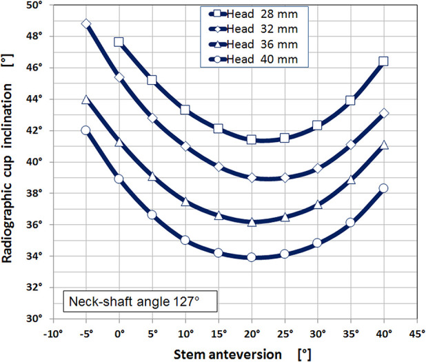
Cup inclination was dependent on stem’s anteversion and head size. Lowest compatible cup inclinations corresponded to 15° to 25° stem anteversion. By increasing the head diameter lower cup inclination could be chosen.
Fig. 11.
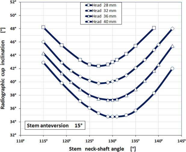
Cup inclination was dependent on stem’s neck-shaft angle and head size. Lowest compatible cup inclinations corresponded to 125° to 133° neck-shaft angle. Again, by increasing the head diameter lower cup inclination could be chosen.
Changing stem anteversion required cup anteversion to be adjusted in the opposite direction, that is, increasing stem anteversion called for a reduction in cup anteversion and vice versa. The linear regression analysis for a 127° neck-shaft-angle stem showed this equation: Cup Anteversion + 0.68*Stem Anteversion = 31.3°, the coefficient of determination R2 was 0.9969 (Fig. 12). This correlation is called combined version. The contribution of stem anteversion to the combined version value was only 68% compared with 100% of cup anteversion. Therefore, it is more effective to adjust the cup than the stem to satisfy this equation. Changing the neck-shaft angle also changed combined version. For example, in a straight stem with a neck-shaft angle of 121°, the combined version was 24°, while it was 33° for a stem with a 135° neck-shaft angle (Fig. 13). Therefore, the combined version also was dependent on prosthesis design and was not the same for all prosthesis designs.
Fig. 12.
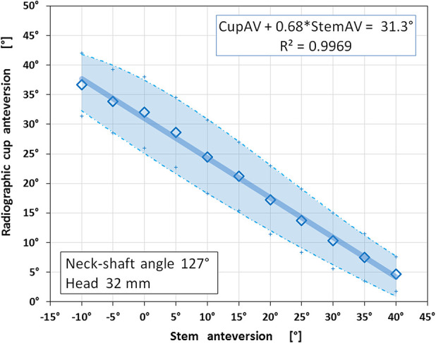
Cup anteversion and stem anteversion were correlated inverse-linearly. Low cup anteversion combined best with high-stem anteversion and vice versa supporting the combined version concept. The shaded area outlines the safety margin for component orientations that fulfill the intended ROMs (Table 2 ) (neck-shaft angle is 127°).
Fig. 13.
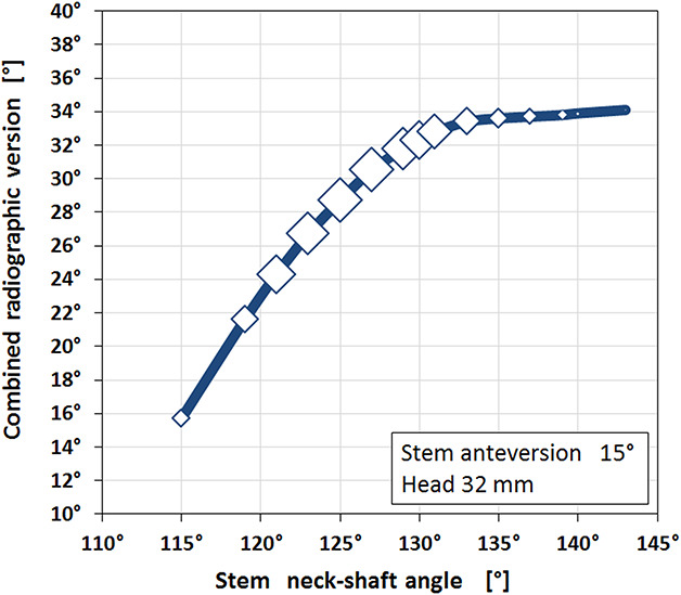
Combined version was dependent on neck-shaft angle. Greater neck-shaft angles required greater combined versions. There was a ceiling effect showing an asymptotic leveling at 34° of combined version. The marker size represents the relative size of the combined target zone showing the largest zones from 123° to 130° neck-shaft angles corresponding to 25° to 32° combined radiographic version (head size is 32 mm, stem anteversion is 15°).
The design that provided the largest combined target zones using a 32 mm head was a straight stem with a 127° neck-shaft angle that was implanted at 15° stem anteversion and was combined with a cup implanted at 40° cup inclination and 20° radiographic anteversion resulting in a combined version of 31°. When the head size was increased, the corresponding lowest possible cup inclination decreased: Cup inclination was 42° for a 28-mm head, 40° for a 32-mm head, 38° for a 36-mm head, and 36° for a 40-mm head.
Discussion
Impingement-free component orientation is a cornerstone for enhanced joint stability in THA. This study identified a multifactorial, dynamic interplay between cup and stem that must be considered when aiming to maximize the impingement-free ROM. This interplay involves both design and implantation parameters, such as head size, head/neck-ratio, neck-shaft angle, stem anteversion, cup inclination, and anteversion. Hence, considering both components is of upmost importance [31]. An accurate best-fit combination of component orientations providing the largest combined target zone was identified (Fig. 5). Changing one or more component orientations or design parameters results in the need for the other parameters. The combined target zone is a guide for how to perform these adjustments to achieve the widest impingement-free ROM possible.
Limitations
The study has several limitations. First, it is theoretical in nature and second it addresses prosthetic impingement only. On one hand, being theoretical is a big advantage because any design or any component orientation or any prosthetic joint movement can be tested virtually in the computer-aided design system. On the other hand, the scope of all test parameters had to be limited to the range that is actually used in clinical practice. This means the parameters should include realistic numbers. For example, for stem anteversion the lowest value was -10° and the highest was 40°; it would not make sense to test 90° stem anteversion even though the algorithm would process it. The hip movements selected for testing were predefined based on available evidence [46, 55, 67]. Although this set of movements included various combined flexing/extending + internal/external rotating + ab/adducting movements that are known to trigger dislocation, the combined target zones are still limited to the parameters tested and movements that diminish the target zones even further are possible.
Obviously, by addressing prosthetic impingement only, bone-on-bone or implant-one-bone or soft tissue impingement were not covered. Furthermore, patient-specific parameters like sex, age, BMI, or height were not included in the modeling. This has been done intentionally since the goal was to test just the impingement-free prosthetic ROM of a straight stem/hemispheric cup type prosthesis. As is known, a THA needs more factors to be successful, including meticulous surgical technique, consideration of relevant biomechanical aspects during preoperative planning [25, 42], attention to systemic risk factors, and adequate physiotherapy. Finally, we note that orienting the components is only one step in prosthesis implantation; containment, that is, achieving as much bone coverage as possible [94], and component fixation [96] are additional important aspects.
Target Zones for Cup and Stem Orientation
We developed a computer model to determine the target zones for cup and stem orientation and implant design in a hypothetical THA implant of a parameterized geometry (that is, expressing implant geometry in terms of changing design parameters) so as to maximize impingement-free ROM. First, we found that for a 127° neck-shaft angle, 15° stem anteversion, 32 mm femoral head, 2.67 head-neck ratio, and a hemispherical shell, the impingement-free targets were 40° for cup inclination, 20° for cup anteversion, and 31° for combined version. We also found tolerance ranges for each component orientation.
Lewinnek’s recommendations for the cup are close to these results, provided that a 127°-neck-shaft-angle stem is used and the functional stem anteversion is adjusted to 20°. Therefore, when putting a 127°-straight stem into 20° anteversion, the surgeon should continue to apply Lewinnek’s recommendation for cup placement [50]. But there are important points to consider: Our target zone was smaller than Lewinnek’s safe zone and one that was estimated by another recent modeling study [27]. In particular, putting the cup into lower inclination and lower anteversion is not recommended because a cup at 30° inclination and at 5° anteversion was outside the polygonal shape of the combined target zone that we found (Fig. 2). A rectangular safe zone, such as the one posited by Lewinnek et al. [50], would therefore leave a surgeon (and his or her patient) vulnerable to an alignment error that could result in impingement or dislocation. Indeed, adjusting cup and stem orientation in tandem is an important detail in THA, and the Lewinnek safe-zone does not adequately make this clear. Furthermore, we confirmed the important inverse-linear correlation between stem anteversion and cup anteversion (Fig. 12). This inverse-linear regression is related to the concept of combined version and has been demonstrated for one specific prosthesis design [95], and it also has been confirmed by other investigators [6, 39, 41, 99]. Its clinical impact—improving THA stability—has been demonstrated in clinical studies for primary and also for revision surgery [22, 52, 60, 64]. We found that the combined target zone is located at a higher (Fig. 3) or lower location in the diagram depending on stem anteversion (Fig. 4).
How Implant Positions Varied with Changes in Component Design
By increasing the head size and the head/neck ratio, the target zone size also increased, meaning that the range for orienting the hemispheric cup was wider. Hence, prosthetic impingement was less likely to occur when we modeled a THA using a larger head with a larger head/neck ratio, and consequently the risk for dislocation might be reduced when using implants with those design features [15]. Clinical experience supports the stabilizing impact of larger heads [40]. However, there are potential concerns with larger femoral heads, such as an increased corrosion risk at the head-neck trunnion [9] or wear [19], and so the surgeon needs to consider the potential trade-offs of these implant-selection choices. The combined target zone expanded to higher and lower cup anteversion but also to lower cup inclination. The clinical conclusion of the latter observation is that the cup should be implanted at the lowest inclination possible, which will make the jumping distance higher [63, 75] and will improve tribology [4, 52]. In addition, we observed that when the head size changed, the neck-shaft angle, stem anteversion, and cup anteversion did not have to be changed, and the combined version remained the same.
Neck-shaft angles between 122° and 130° yielded the largest target zones. Stems with equal to or less than 115° or greater than 135° neck-shaft angles provided substantially smaller target zones. Neck-shaft angle also determined the cup inclination. Lowest cup inclination was possible for 127° to 131° neck-shaft angles. Neck-shaft angle also influenced cup anteversion (Fig. 6) and combined version (Fig. 10), demonstrating that combined version is not a constant value for all prostheses but was dependent on design and implantation parameters [41, 64]. In other words, combined version is also a prosthesis-specific parameter.
Clinical Relevance
Preventing dislocation in THA is an important goal. Although hip instability is multifactorial, it seems important to reduce the risk of prosthetic impingement. If a THA joint is unstable, despite adopting the components to orientations as presented here, it is very likely that one or more other causes are triggering instability, and these might need correction. It should also be noted that individual changes in pelvic tilt intra- or postoperatively do affect functional cup orientation [5, 8] and should be considered during surgery [35, 47, 76, 78, 101].
Conclusions
We determined the multidimensional interrelationship of impingement-free component orientation using a hypothetical hip prosthesis representing a straight-stem type prosthesis. We determined design-specific recommendations for cup and stem orientation to maximize an impingement-free target zone. We also calculated adjustments to those orientations when the position of one or both components was changed (Fig. 5). The analysis provided recommendations on how to reach the largest ROM for a prosthesis with design parameters familiar to many surgeons (straight stem, hemispherical shell). Transformation of these results into precise component implantation during surgery may benefit from additional tools like navigation and/or robotics [14, 17, 29, 43, 44, 49, 59, 80, 81, 82]; however, this is speculative and as of now, unproven. Future clinical studies might show if such prosthesis- and patient-adjusted component orientations will help to enhance THA stability in our patients.
Acknowledgments
I thank my mentor, Prof. Dr.med. Erwin Morscher, MD, for igniting my interest for THA and for continuing discussions.
Footnotes
All ICMJE Conflict of Interest Forms for authors and Clinical Orthopaedics and Related Research® editors and board members are on file with the publication and can be viewed on request.
The author certifies that he has no commercial associations (consultancies, stock ownership, equity interest, patent/licensing arrangements, etc.) that might pose a conflict of interest in connection with the submitted article.
The author certifies that his institution approved the reporting of this investigation and that all investigations were conducted in conformity with ethical principles of research.
This work was performed at Kantonsspital Baselland, Switzerland, and at Medical Faculty University of Basel, Basel, Switzerland.
References
- 1.Abdel MP, von Roth P, Jennings MT, Hanssen AD, Pagnano MW. What safe zone? The vast majority of dislocated THAs are within the Lewinnek safe zone for acetabular component position. Clin Orthop Relat Res. 2016;474:386-391. [DOI] [PMC free article] [PubMed] [Google Scholar]
- 2.Abe H, Sakai T, Hamasaki T, Takao M, Nishii T, Nakamura N, Sugano N. Is the transverse acetabular ligament a reliable cup orientation guide? Computer simulation in 160 hips. Acta Orthop. 2012;83:474-480. [DOI] [PMC free article] [PubMed] [Google Scholar]
- 3.Ala Eddine T, Migaud H, Chantelot C, Cotten A, Fontaine C, Duquennoy A. Variations of pelvic anteversion in the lying and standing positions analysis of 24 control subjects and implications for CT measurement of position of a prosthetic cup. Surg Radiol Anat. 2001;23:105-110. [DOI] [PubMed] [Google Scholar]
- 4.Ardestani MM, Amenábar Edwards PP, Wimmer MA. Prediction of polyethylene wear rates from gait biomechanics and implant positioning in total hip replacement. Clin Orthop Relat Res. 2017;475:2027-2042. [DOI] [PMC free article] [PubMed] [Google Scholar]
- 5.Babisch JW, Layher F, Amiot LP. The rationale for tilt-adjusted acetabular cup navigation. J Bone Joint Surg Am. 2008;90:357-365. [DOI] [PubMed] [Google Scholar]
- 6.Barsoum WK, Patterson RW, Higuera C, Klika AK, Krebs VE, Molloy R. A computer model of the position of the combined component in the prevention of impingement in total hip replacement. J Bone Joint Surg Br. 2007;89:839–845. [DOI] [PubMed] [Google Scholar]
- 7.Batailler C, Weidner J, Wyatt M, Dalmay F, Beck M. Position of the greater trochanter and functional femoral antetorsion: which factors matter in the management of femoral antetorsion disorders? Bone Joint J. 2018;100:712–719. [DOI] [PubMed] [Google Scholar]
- 8.Bedard NA, Martin CT, Slaven SE, Pugely AJ, Mendoza-Lattes SA, Callaghan JJ. Abnormally High Dislocation Rates of Total Hip Arthroplasty After Spinal Deformity Surgery. J Arthroplasty. 2016;31:2884–2885. [DOI] [PubMed] [Google Scholar]
- 9.Berstock JR, Whitehouse MR, Duncan CP. Trunnion corrosion: what surgeons need to know in 2018. Bone Joint J . 2018. January;100-B(1 Suppl A):44-49. [DOI] [PMC free article] [PubMed] [Google Scholar]
- 10.Beverland DE, O’Neill CKJ, Rutherford M, Molloy D, Hill JC. Placement of the acetabular component. Bone Joint J. 2016;98:37–43. [DOI] [PubMed] [Google Scholar]
- 11.Blondel B, Parratte S, Tropiano P, Pauly V, Aubaniac J-M, Argenson JN. Pelvic tilt measurement before and after total hip arthroplasty. Orthop Traumatol Surg Res . 2009;95:568–572. [DOI] [PubMed] [Google Scholar]
- 12.Brown TD, Callaghan JJ. Impingement in total hip replacement: mechanisms and consequences. Curr Orthop. 2008;22:376–391. [DOI] [PMC free article] [PubMed] [Google Scholar]
- 13.Buckland AJ, Puvanesarajah V, Vigdorchik J, Schwarzkopf R, Jain A, Klineberg EO, Hart RA, Callaghan JJ, Hassanzadeh H. Dislocation of a primary total hip arthroplasty is more common in patients with a lumbar spinal fusion. Bone Joint J. 2017;99:585–591. [DOI] [PubMed] [Google Scholar]
- 14.Buller LT, McLawhorn AS, Romero JA, Sculco PK, Mayman DJ. Accuracy and precision of acetabular component placement with imageless navigation in obese patients. J Arthroplasty. 2019;34:693–699. [DOI] [PubMed] [Google Scholar]
- 15.Burroughs BR, Hallstrom B, Golladay GJ, Hoeffel D, Harris WH. Range of motion and stability in total hip arthroplasty With 28-, 32-, 38-, and 44-mm femoral head sizes. J Arthroplasty. 2005;20:11–19. [DOI] [PubMed] [Google Scholar]
- 16.Charnley J. Low Friction Arthroplasty of the Hip: Theory and Practice . Berlin, Heidelberg: Springer Berlin Heidelberg; 1979. [Google Scholar]
- 17.Chow J, Pearce S, Cho K, Walter W. Direct anterior approach using navigation improves accuracy of cup position compared to conventional posterior approach. Cureus. 2017;9:e1482. [DOI] [PMC free article] [PubMed] [Google Scholar]
- 18.Cinotti G, Lucioli N, Malagoli A, Calderoli C, Cassese F. Do large femoral heads reduce the risks of impingement in total hip arthroplasty with optimal and non-optimal cup positioning? Int Orthop. 2011;35:317–323. [DOI] [PMC free article] [PubMed] [Google Scholar]
- 19.Daines BK, Dennis DA. The importance of acetabular component position in total hip arthroplasty. Orthop Clin North Am . 2012;43:e23-34. [DOI] [PubMed] [Google Scholar]
- 20.DiGioia AM, Hafez MA, Jaramaz B, Levison TJ, Moody JE. Functional pelvic orientation measured from lateral standing and sitting radiographs. Clin Orthop Relat Res. 2006;453:272–276. [DOI] [PubMed] [Google Scholar]
- 21.Dimitriou D, Tsai T-Y, Li J-S, Nam KW, Park KK, Kwon Y-M. In vivo kinematic evaluation of total hip arthroplasty during stair climbing: total Hip Step-up. J Orthop Res. 2015;33:1087–1093. [DOI] [PubMed] [Google Scholar]
- 22.Dorr LD, Malik A, Dastane M, Wan Z. Combined anteversion technique for total hip arthroplasty. Clin Orthop Relat Res. 2009;467:119–127. [DOI] [PMC free article] [PubMed] [Google Scholar]
- 23.Durgin CF, Spratley EM, Satpathy J, Jiranek WA, Wayne JS. Novel potential marker for native anteversion of the proximal femur: potential marker for proximal femoral native anteversion. J Orthop Res. 2017;35:1724–1731. [DOI] [PubMed] [Google Scholar]
- 24.Eftekhary N, Shimmin A, Lazennec JY, Buckland A, Schwarzkopf R, Dorr LD, Mayman D, Padgett D, Vigdorchik J. A systematic approach to the hip-spine relationship and its applications to total hip arthroplasty. Bone Joint J. 2019;101:808–816. [DOI] [PubMed] [Google Scholar]
- 25.Eggli S, Pisan M, Müller ME. The value of preoperative planning for total hip arthroplasty. J Bone Joint Surg Br. 1998;80:382-90. [DOI] [PubMed] [Google Scholar]
- 26.Eilander W, Harris SJ, Henkus HE, Cobb JP, Hogervorst T. Functional acetabular component position with supine total hip replacement. Bone Joint J. 2013;95:1326–1331. [DOI] [PubMed] [Google Scholar]
- 27.Elkins JM, Callaghan JJ, Brown TD. The 2014 Frank Stinchfield Award: The ‘landing zone’ for wear and stability in total hip arthroplasty is smaller than we thought: a computational analysis. Clin Orthop Relat Res. 2015;473:441–452. [DOI] [PMC free article] [PubMed] [Google Scholar]
- 28.Elkins JM, O’Brien MK, Stroud NJ, Pedersen DR, Callaghan JJ, Brown TD. Hard-on-hard total hip impingement causes extreme contact stress concentrations. Clin Orthop Relat Res. 2011;469:454–463. [DOI] [PMC free article] [PubMed] [Google Scholar]
- 29.Elson L, Dounchis J, Illgen R, Marchand RC, Padgett DE, Bragdon CR, Malchau H. Precision of acetabular cup placement in robotic integrated total hip arthroplasty. Hip Int. 2015;25:531–536. [DOI] [PubMed] [Google Scholar]
- 30.Esposito CI, Carroll KM, Sculco PK, Padgett DE, Jerabek SA, Mayman DJ. Total hip arthroplasty patients with fixed spinopelvic alignment are at higher risk of hip dislocation. J Arthroplasty. 2018;33:1449–1454. [DOI] [PubMed] [Google Scholar]
- 31.Esposito CI, Gladnick BP, Lee Y, Lyman S, Wright TM, Mayman DJ, Padgett DE. Cup position alone doesn predict risk of dislocation after hip arthroplasty. J Arthroplasty. 2015;30:109–113. [DOI] [PMC free article] [PubMed] [Google Scholar]
- 32.Esposito CI, Miller TT, Kim HJ, Barlow BT, Wright TM, Padgett DE, Jerabek SA, Mayman DJ. Does degenerative lumbar spine disease influence femoroacetabular flexion in patients undergoing total hip arthroplasty? Clin Orthop Relat Res . 2016;474:1788–1797. [DOI] [PMC free article] [PubMed] [Google Scholar]
- 33.Esposito CI, Miller TT, Lipman JD, Carroll KM, Padgett DE, Mayman DJ, Jerabek SA. Biplanar low-dose radiography is accurate for measuring combined anteversion after total hip arthroplasty. HSS J. 2020 Feb;16(1):23-29. [DOI] [PMC free article] [PubMed] [Google Scholar]
- 34.Furuhashi H, Togawa D, Koyama H, Hoshino H, Yasuda T, Matsuyama Y. Repeated posterior dislocation of total hip arthroplasty after spinal corrective long fusion with pelvic fixation. Eur Spine J. 2017;26:100–106. [DOI] [PubMed] [Google Scholar]
- 35.Grammatopoulos G, Alvand A, Monk AP, Mellon S, Pandit H, Rees J, Gill HS, Murray DW. Surgeons’ accuracy in achieving their desired acetabular component orientation. J Bone Joint Surg Am. 2016;98:e72. [DOI] [PubMed] [Google Scholar]
- 36.Grood E, Suntay W. A joint coordinate system for the clinical description of three-dimensional motions: Application to the knee. J Biomech Eng. 1983;105:136–144. [DOI] [PubMed] [Google Scholar]
- 37.Hamill J, Knutzen K, Derrick T. Biomechanical Basis of Human Motion, 4th ed. Lippincott Williams & Wilkins; 2015. [Google Scholar]
- 38.Heckmann N, McKnight B, Stefl M, Trasolini NA, Ike H, Dorr LD. Late dislocation following total hip arthroplasty: Spinopelvic imbalance as a causative factor. J Bone Joint Surg Am. 2018;100:1845–1853. [DOI] [PubMed] [Google Scholar]
- 39.Hisatome T, Doi H. Theoretically optimum position of the prosthesis in total hip arthroplasty to fulfill the severe range of motion criteria due to neck impingement. J Orthop Sci. 2011;16:229–237. [DOI] [PubMed] [Google Scholar]
- 40.Howie DW, Holubowycz OT, Middleton R. Large femoral heads decrease the incidence of dislocation after total hip arthroplasty: a randomized controlled trial. J Bone Joint Surg Am. 2012;20;94:1095-102. [DOI] [PubMed] [Google Scholar]
- 41.Hsu J, de la Fuente M, Radermacher K. Calculation of impingement-free combined cup and stem alignments based on the patient-specific pelvic tilt. J Biomech . 2019;82:193–203. [DOI] [PubMed] [Google Scholar]
- 42.Imai H, Miyawaki J, Kamada T, Takeba J, Mashima N, Miura H. Preoperative planning and postoperative evaluation of total hip arthroplasty that takes combined anteversion. Eur. J Orthop Surg Traumatol. 2016;26:493–500. [DOI] [PMC free article] [PubMed] [Google Scholar]
- 43.Inaba Y, Kobayashi N, Ike H, Kubota S, Saito T. The current status and future prospects of computer-assisted hip surgery. J Orthop Sci. 2016;21:107–115. [DOI] [PubMed] [Google Scholar]
- 44.Jolles BM, Genoud P, Hoffmeyer P. Computer-assisted cup placement techniques in total hip arthroplasty improve accuracy of placement. Clin Orthop Relat Res . 2004;426:174–179. [DOI] [PubMed] [Google Scholar]
- 45.Kanawade V, Dorr LD, Wan Z. Predictability of acetabular component angular change with postural shift from standing to sitting position. J Bone Joint Surg Am . 2014;96:978–986. [DOI] [PubMed] [Google Scholar]
- 46.Kapandji IA. Physiology of the Joints. Vol 2, Lower Limb. 6th ed, London: Churchill Livingstone; 2010. [Google Scholar]
- 47.Kyo T, Nakahara I, Miki H. Factors predicting change in pelvic posterior tilt after THA. Orthopedics. 2013;36:e753–e759. [DOI] [PubMed] [Google Scholar]
- 48.Lazennec JY, Rousseau MA, Brusson A, Folinais D, Amel M, Clarke I, Pour AE. Total hip prostheses in standing, sitting and squatting positions: An overview of our 8 years practice using the EOS imaging technology. Open Orthop J . 2015;9:26–44. [DOI] [PMC free article] [PubMed] [Google Scholar]
- 49.Lee S, Kim JY, Hong J, Baek SH, Kim SY. CT-based navigation system using a patient-specific instrument for femoral Component positioning: An experimental in vitro study with a Sawbone model. Yonsei Med J . 2018;59:769-780. [DOI] [PMC free article] [PubMed] [Google Scholar]
- 50.Lewinnek GE, Lewis JL, R Tarr R, Compere CL, Zimmerman JR. Dislocations after total hip-replacement arthroplasties. J Bone Joint Surg Am. 1978;60:217-220. [PubMed] [Google Scholar]
- 51.Maratt JD, Esposito CI, McLawhorn AS, Jerabek SA, Padgett DE, Mayman DJ. Pelvic tilt in patients undergoing total hip arthroplasty: When does it matter? J Arthroplasty. 2015;30:387–391. [DOI] [PMC free article] [PubMed] [Google Scholar]
- 52.Mayeda BF, Haw JG, Battenberg AK, Schmalzried TP. Femoral-acetabular mating: the effect of femoral and combined anteversion on cross-linked polyethylene wear. J Arthroplasty. 2018;33:3320–3324. [DOI] [PubMed] [Google Scholar]
- 53.McKibbin B. Anatomical factors in the stability of the hip joint in the newborn. J Bone Joint Surg Br. 1970;52:148–159. [PubMed] [Google Scholar]
- 54.Miki H, Kyo T, Sugano N. Anatomical hip range of motion after implantation during total hip arthroplasty with a large change in pelvic inclination. J Arthroplasty. 2012;27:1641-1650. [DOI] [PubMed] [Google Scholar]
- 55.Mulholland SJ, UP Wyss. Activities of daily living in non-Western cultures: range of motion requirements for hip and knee joint implants: Int J Rehabil Res . 2001;24:191–198. [DOI] [PubMed] [Google Scholar]
- 56.Murphy WS, Klingenstein G, Murphy SB, Zheng G. Pelvic tilt is minimally changed by total hip arthroplasty. Clin Orthop Relat Res . 2013;471:417–421. [DOI] [PMC free article] [PubMed] [Google Scholar]
- 57.Murray DW. The definition and measurement of acetabular orientation. J Bone Joint Surg Br . 1993;75:228–232. [DOI] [PubMed] [Google Scholar]
- 58.Nadzadi ME, Pedersen DR, Yack HJ, Callaghan JJ, Brown TD. Kinematics, kinetics, and finite element analysis of commonplace maneuvers at risk for total hip dislocation. J Biomech. 2003;36:577–591. [DOI] [PubMed] [Google Scholar]
- 59.Najarian BC, Kilgore JE, Markel DC. Evaluation of component positioning in primary total hip arthroplasty using an imageless navigation device compared with traditional methods. J Arthroplasty . 2009;24:15–21. [DOI] [PubMed] [Google Scholar]
- 60.Nakashima Y, Hirata M, Akiyama M, Itokawa T, Yamamoto T, Motomura G, Ohishi M, Hamai S, Iwamoto Y. Combined anteversion technique reduced the dislocation in cementless total hip arthroplasty. Int Orthop. 2014;38:27–32. [DOI] [PMC free article] [PubMed] [Google Scholar]
- 61.Nishiwaki T, Hata R, Oya A, Nakamura M, Matsumoto M, Kanaji A. Pelvic tilt displacement before and after artificial hip joint replacement surgery. J Arthroplasty . 2018;33:925–930. [DOI] [PubMed] [Google Scholar]
- 62.Ochi H, Baba T, Homma Y, Matsumoto M, Nojiri H, Kaneko K. Importance of the spinopelvic factors on the pelvic inclination from standing to sitting before total hip arthroplasty. Eur Spine J. 2016;25:3699–3706. [DOI] [PubMed] [Google Scholar]
- 63.Ohmori T, Kabata T, Kajino Y, Inoue D, Taga T, Yamamoto T, Takagi T, Yoshitani J, Ueno T, Ueoka K, Tsuchiya H. Effect of changing femoral head diameter on bony and prosthetic jumping angles. Eur J Orthop Surg Traumatol. 2019;29:625–632. [DOI] [PubMed] [Google Scholar]
- 64.Ohmori T, Kabata T, Kajino Y, Taga T, Hasegawa K, Inoue D, Yamamoto T, Takagi T, Yoshitani J, Ueno T, Tsuchiya H. Differences in range of motion with the same combined anteversion after total hip arthroplasty. Int Orthop . 2018;42:1021–1028. [DOI] [PubMed] [Google Scholar]
- 65.Okanoue Y, Ikeuchi M, Takaya S, Izumi M, Aso K, Kawakami T. Chronological changes in functional cup position at 10 years after total hip arthroplasty. Hip Int . 2017;27:477–482. [DOI] [PubMed] [Google Scholar]
- 66.Patel AB, Wagle RR, Usrey MM, Thompson MT, Incavo SJ, Noble PC. Guidelines for implant placement to minimize impingement during activities of daily living after total hip arthroplasty. J Arthroplasty . 2010;25:1275-1281. [DOI] [PubMed] [Google Scholar]
- 67.Pedersen DR, Callaghan JJ, Brown TD. Activity-dependence of the “safe zone” for impingement versus dislocation avoidance. Med Eng Phys. 2005;27:323–328. [DOI] [PubMed] [Google Scholar]
- 68.Perfetti DC, Schwarzkopf R, Buckland AJ, Paulino CB, Vigdorchik JM. Prosthetic dislocation and revision after primary total hip arthroplasty in lumbar fusion patients: a propensity score matched-pair analysis. J Arthroplasty. 2017;32:1635-1640. [DOI] [PubMed] [Google Scholar]
- 69.Pierrepont J, Hawdon G, Miles BP, Connor BO, Baré J, Walter LR, Marel E, Solomon M, McMahon S, Shimmin AJ. Variation in functional pelvic tilt in patients undergoing total hip arthroplasty. Bone Joint J . 2017;99:184–191. [DOI] [PubMed] [Google Scholar]
- 70.Ranawat CS. Modern techniques of cemented total hip arthroplasty. Techniques Orthoped. 1991;6:17–25. [Google Scholar]
- 71.Ranawat CS, Ranawat AS, Lipman JD, White PB, Meftah M. Effect of spinal deformity on pelvic orientation from standing to sitting position. J Arthroplasty . 2016;31:1222–1227. [DOI] [PubMed] [Google Scholar]
- 72.Reina N, Putman S, Desmarchelier R, Sari Ali E, Chiron P, Ollivier M, Jenny JY, Waast D, Mabit C, de Thomasson E, Schwartz C, Oger P, Gayet LE, Migaud H, Ramdane N, Fessy MH. Can a target zone safer than Lewinnek’s safe zone be defined to prevent instability of total hip arthroplasties? Case-control study of 56 dislocated THA and 93 matched controls. Orthop Traumatol Surg Res. 2017;103:657–661. [DOI] [PubMed] [Google Scholar]
- 73.Robinson RP, Simonian PT, Gradisar IM, Ching RP. Joint motion and surface contact area related to component position in total hip arthroplasty. J Bone Joint Surg Br. 1997;79:140-146. [DOI] [PubMed] [Google Scholar]
- 74.Ross JR, Tannenbaum EP, Nepple JJ, Kelly BT, Larson CM, Bedi A. Functional acetabular orientation varies between supine and standing radiographs: implications for treatment of femoroacetabular impingement. Clin Orthop Relat Res. 2015;473:1267–1273. [DOI] [PMC free article] [PubMed] [Google Scholar]
- 75.Sariali E, Lazennec JY, Khiami F, Catonné Y. Mathematical evaluation of jumping distance in total hip arthroplasty: influence of abduction angle, femoral head offset, and head diameter. Acta Orthop. 2009;80:277-82. [DOI] [PMC free article] [PubMed] [Google Scholar]
- 76.Schloemann DT, Edelstein AI, Barrack RL. Changes in acetabular orientation during total hip arthroplasty. Bone Joint J. 2019;101:45–50. [DOI] [PubMed] [Google Scholar]
- 77.Seki M, Yuasa N, Ohkuni K. Analysis of optimal range of socket orientations in total hip arthroplasty with use of computer-aided design simulation. J Orthop Res . 1998;16:513–517. [DOI] [PubMed] [Google Scholar]
- 78.Shah SM, Walter WL, Ngo J. Is the pelvis stable during supine total hip arthroplasty? Acta Orthop Belg . 2017;83:81–86. [PubMed] [Google Scholar]
- 79.Sing DC, Barry JJ, Aguilar TU, Theologis AA, Patterson JT, Tay BK, Vail TP, Hansen EN. Prior lumbar spinal arthrodesis increases risk of prosthetic-related complication in total hip arthroplasty. J Arthroplasty . 2016;31:227-232. [DOI] [PubMed] [Google Scholar]
- 80.Spencer-Gardner L, Pierrepont J, Topham M, Baré J, McMahon S, Shimmin AJ. Patient-specific instrumentation improves the accuracy of acetabular component placement in total hip arthroplasty. Bone Joint J . 2016;98:1342–1346. [DOI] [PubMed] [Google Scholar]
- 81.Steppacher SD, Kowal JH, Murphy SB. Improving cup positioning using a mechanical navigation instrument. Clin Orthop Relat Res. 2011;469:423–428. [DOI] [PMC free article] [PubMed] [Google Scholar]
- 82.Sugano N, Takao M, Sakai T, Nishii T, Miki H, Nakamura N. Comparison of mini-incision total hip arthroplasty through an anterior approach and a posterior approach using navigation. Orthop Clin North Am. 2009;40:365–370. [DOI] [PubMed] [Google Scholar]
- 83.Taki N, Mitsugi N, Mochida Y, Akamatsu Y, Saito T. Change in pelvic tilt angle 2 to 4 years after total hip arthroplasty. J Arthroplasty . 2012;27:940–944. [DOI] [PubMed] [Google Scholar]
- 84.Tamura S, Takao M, Sakai T, Nishii T, Sugano N. Spinal factors influencing change in pelvic sagittal inclination from supine position to standing position in patients before total hip arthroplasty. J Arthroplasty. 2014;29:2294–2297. [DOI] [PubMed] [Google Scholar]
- 85.Tezuka T, Heckmann ND, Bodner RJ, Dorr LD. Functional safe zone is superior to the Lewinnek safe zone for total hip arthroplasty: Why the Lewinnek safe zone is not always predictive of stability. J Arthroplasty. 2019;34:3–8. [DOI] [PubMed] [Google Scholar]
- 86.Tian J, Sun L, Hu R, Han W, Tian X. Long-term Results of primary hip arthroplasty with cup inclination angle bigger than fifty degrees. J Clin Orthop Trauma. 2018 Apr-Jun;9(2):133-136. [DOI] [PMC free article] [PubMed] [Google Scholar]
- 87.Tiberi JV, Antoci V, Malchau H, Rubash HE, Freiberg AA, Kwon YM. What is the fate of total hip arthroplasty (THA) acetabular component orientation when evaluated in the standing position? J Arthroplasty. 2015;30:1555–1560. [DOI] [PubMed] [Google Scholar]
- 88.Turley GA, Griffin DR, Williams MA. Effect of femoral neck modularity upon the prosthetic range of motion in total hip arthroplasty. Med Biol Eng Comput . 2014;52:685–694. [DOI] [PMC free article] [PubMed] [Google Scholar]
- 89.Uemura K, Takao M, Otake Y, Koyama K, Yokota F, Hamada H, Sakai T, Sato Y, Sugano N. Can anatomic measurements of stem anteversion angle be considered as the functional anteversion angle? J Arthroplasty. 2018;33:595–600. [DOI] [PubMed] [Google Scholar]
- 90.Uemura K, Takao M, Sakai T, Nishii T, Sugano N. The validity of using the posterior condylar line as a rotational reference for the femur. J Arthroplasty . 2016;31:302–306. [DOI] [PubMed] [Google Scholar]
- 91.Walter WL, O’Toole GC, Walter WK, Ellis A, Zicat BA. Squeaking in ceramic-on-ceramic hips. J Arthroplasty . 2007;22:496–503. [DOI] [PubMed] [Google Scholar]
- 92.Wan Z, Boutary M, Dorr LD. The influence of acetabular component position on wear in total hip arthroplasty. J Arthroplasty. 2008;23:51-56. [DOI] [PubMed] [Google Scholar]
- 93.Wells J, Nepple JJ, Crook K, Ross JR, Bedi A, Schoenecker P, Clohisy JC. Femoral morphology in the dysplastic hip: three-dimensional characterizations with CT. Clin Orthop Relat Res . 2017;475:1045–1054. [DOI] [PMC free article] [PubMed] [Google Scholar]
- 94.Widmer KH. Containment versus impingement: finding a compromise for cup placement in total hip arthroplasty. Int Orthop . 2007;31:29–33. [DOI] [PMC free article] [PubMed] [Google Scholar]
- 95.Widmer KH, Zurfluh B. Compliant positioning of total hip components for optimal range of motion. J Orthop Res . 2004;22:815–821. [DOI] [PubMed] [Google Scholar]
- 96.Widmer KH, Zurfluh B, Morscher EW.Load transfer and fixation mode of press-fit acetabular sockets. J Arthroplasty . 2002;17:926-35. [DOI] [PubMed] [Google Scholar]
- 97.Worlicek M, Weber M, Craiovan B, Wörner M, Völlner F, Springorum HR, Grifka J, Renkawitz T. Native femoral anteversion should not be used as reference in cementless total hip arthroplasty with a straight, tapered stem: a retrospective clinical study. BMC Musculoskelet Disord . 2016;17:399. [DOI] [PMC free article] [PubMed] [Google Scholar]
- 98.Yoon YS, Hodgson AJ, Tonetti J, Masri BA, Duncan CP. Resolving inconsistencies in defining the target orientation for the acetabular cup angles in total hip arthroplasty. Clin Biomech. 2008;23:253–259. [DOI] [PubMed] [Google Scholar]
- 99.Yoshimine F. The safe-zones for combined cup and neck anteversions that fulfill the essential range of motion and their optimum combination in total hip replacements. J Biomech. 2006;39:1315–1323. [DOI] [PubMed] [Google Scholar]
- 100.Yoshitani J, Kabata T, Kajino Y, Ueno T, Ueoka K, Yamamuro Y, Tsuchiya H. Anatomic stem inserted according to native anteversion could reproduce the native anterior distance of the femoral head and decrease bony impingement in total hip arthroplasty. Int Orthop . 2020;44:245-251 [DOI] [PubMed] [Google Scholar]
- 101.Zhu J, Wan Z, Dorr LD. Quantification of pelvic tilt in total hip arthroplasty. Clin Orthop Relat Res. 2010;468:571–575. [DOI] [PMC free article] [PubMed] [Google Scholar]


