Abstract
Transrectal ultrasound (TRUS)-guided systematic biopsy, the current gold standard for the detection of prostate cancer, suffers from low sensitivity for clinically significant cancer. The use of diagnostic multiparametric MRI has increased the relevance of targeted biopsy techniques such as MRI-TRUS fusion biopsy and direct (in-bore) MRI-guided biopsy, which have higher detection rate for clinically significant cancer. Although primarily used in patients who remain at high clinical suspicion for prostate cancer despite a negative systematic biopsy, with the increasing use of upfront diagnostic MRI, these biopsies are expected to replace routine systematic biopsies. This pictorial essay aims to enhance our understanding of the concepts of these biopsy techniques so that they can be performed safely and provide maximum diagnostic yield.
Keywords: Prostate cancer, Systematic biopsy, Targeted biopsy, Fusion biopsy, In-bore biopsy
INTRODUCTION
Prostate cancer is the second most common cancer in men worldwide (1). Unlike other cancers, non-targeted systematic transrectal ultrasound (TRUS)-guided biopsy has remained the gold standard for the detection of prostate cancer in the past three decades. TRUS-guided systematic biopsy has low sensitivity for cancers in the apex and anterolateral peripheral zone as well as in high-volume glands (2). Due to its high intrinsic contrast and multiparametric capabilities, magnetic resonance imaging (MRI) has been extensively used to localize early prostate cancer. Many urologists now prefer to perform upfront diagnostic MRI to categorize the risk of clinically significant prostate cancer and reserve biopsies for lesions with a Prostate Imaging Reporting and Data System score of 3 or more. MRI has also been used for targeting biopsies, primarily in patients with a negative TRUS biopsy result who remain at high clinical suspicion of clinically significant prostate cancer. Compared to TRUS-guided biopsy, MRI-guided biopsy (fusion and in-bore techniques) increases the detection rate of clinically significant cancers and reduces the number of required biopsy cores (3). Large trials such as the PROMIS and PRECISION have validated the increased detection rate of clinically significant cancers for MRI-guided biopsy with an associated reduction in the overdiagnosis of clinically insignificant cancers (4, 5). MRI-TRUS fusion biopsy enables accurate real-time targeting and biopsy site documentation. In-bore MRI-guided biopsy provides the advantage of direct targeting and confirmation of needle placement prior to sampling (6). This article describes the various MRI-targeted biopsy techniques in a pictorial representation to increase our understanding of the concepts and procedures of these techniques.
Biopsy Indications and Planning
Prostate biopsy is currently recommended for men aged 50–69 years with elevated serum prostate specific antigen (PSA) levels (> 3 ng/mL) or abnormal digital rectal examination findings (nodules, induration, and asymmetry) (7). For patients with a prior negative biopsy result, the indications for repeat biopsy are persistent rise in serum PSA, suspicious digital rectal examination findings, or presence of atypical small acinar proliferation (8).
The patient is generally instructed to take a single oral dose of ciprofloxacin as a prophylactic antibiotic a few hours before the procedure (9). Additional anaerobic coverage with tinidazole or clindamycin may be provided if required. A cleansing enema may be provided on the morning of the biopsy.
MRI-TRUS Fusion Biopsies
Cognitive Fusion Biopsy
Using this technique, the radiologist reviews the previously acquired MR images and determines the location of the target lesion relative to normal anatomical landmarks or other fiducials. While performing TRUS, the operator cognitively determines the target lesion site using these fiducials and performs tissue sampling. This biopsy method does not require sophisticated equipment and is relatively inexpensive. The recent FUTURE trial revealed no significant differences in the detection rates of clinically significant prostate cancers between cognitive fusion, software fusion, and MR in-bore biopsies (10). However, some researchers have reported that cognitive fusion is inferior compared to software-based fusion technology since it can miss a significant number of prostate cancers (11, 12). Thus, the validity of cognitive fusion biopsy is debatable. The consensus statement of the American Urological Association (AUA) and Society of Abdominal Radiology (SAR) justifies cognitive fusion biopsies in resource-poor settings but recommends software fusion wherever the expertise and facility are available (13).
Software-Assisted Fusion Biopsy
Several commercial software-assisted MRI-TRUS fusion biopsy platforms are currently available with minor differences in the procedural techniques (Table 1). However, all systems essentially comprise five key steps (Fig. 1). Since the experience of the authors is with the Artemis™ (Eigen, Grass Valley, CA, USA) system, the procedural description in the subsequent sections is primarily based on the same.
Table 1. Summary of Currently Available MRI-TRUS Fusion Biopsy Platforms and Basic Differences in Their Workflow.
| Fusion Biopsy System | TRUS Technique | Probe-Tracking Method | Biopsy Route | Fusion Method |
|---|---|---|---|---|
| Artemis™ (Eigen) | Mechanically stabilized sweep | Mechanical arm with encoders | TR, TP | Elastic |
| BiopSee™(Pi Medical) | Motorized sweep | Stepper with encoders | TR, TP | Rigid |
| RVS™ (Hitachi) | Freehand sweep | Electromagnetic | TR, TP | Rigid |
| UroNav™ (Invivo) | Freehand sweep | Electromagnetic | TR, TP | Elastic |
| Urostation™ (Koelis) | 3D probe | TRUS-TRUS registration | TR, TP | Elastic |
| Virtual Navigator™ (Esaote) | Freehand sweep | Electromagnetic | TR | Rigid |
TP = transperineal, TR = transrectal, TRUS = transrectal ultrasound, 3D = three-dimensional
Fig. 1. Step-by-step workflow of software-assisted MRI–TRUS fusion biopsy.
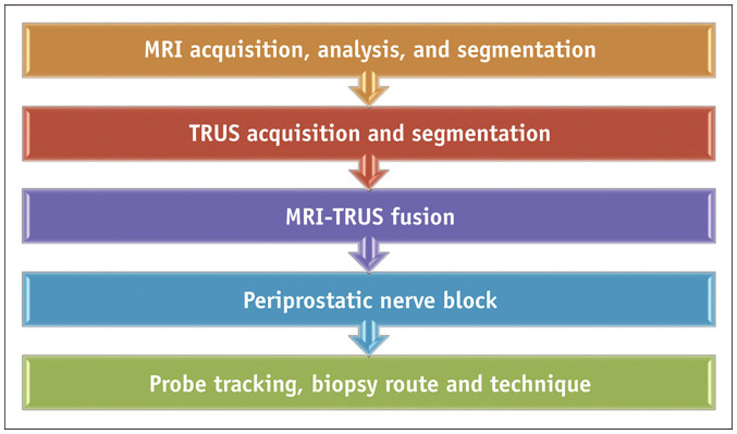
TRUS = transrectal ultrasound
Step 1: MRI Acquisition and Segmentation
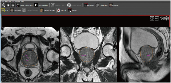
First, the acquired MR images are uploaded onto a segmentation software for mapping the suspicious lesion. The radiologist segments the prostate gland and the target lesion separately on the T2-weighted axial images. The adequacy of the segmented volume can also be verified on the sagittal and coronal images (Fig. 2). The segmented volumes are then fed to the fusion biopsy system.
Fig. 2. Prostate and target lesion segmentation on Profuse™ (Eigen), proprietary segmentation software available with Artemis™ (Eigen) platform.
Radiologist separately segments prostate gland (outlined in yellow) and target lesion (outlined in pink) on axial T2-weighted images (left panel). Adequacy of segmentation can also be verified on synchronized coronal and sagittal images (middle and right panels).
Step 2: TRUS Acquisition and Segmentation
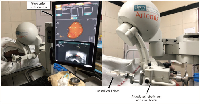
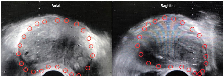
The fusion biopsy system consists of a workstation with monitor, an articulated robotic arm, and a transducer holder (Fig. 3). Subsequently, the transducer attached to the articulated arm is used to perform a mechanically stabilized real-time TRUS sweep of the gland and the prostate is segmented manually (Fig. 4).
Fig. 3. Artemis™ MRI–TRUS fusion biopsy system.
System consists of workstation with monitor, articulated robotic arm, and holder to which TRUS transducer is attached.
Fig. 4. Prostate gland segmentation of TRUS volume.
Transducer attached to articulated arm is used to perform mechanically stabilized craniocaudal sweep of gland. Prostate gland (red outline) is then manually segmented on axial and sagittal TRUS images.
Step 3: MRI-TRUS Fusion
The system fuses the MRI and TRUS volumes and presumptively identifies the location of the target lesion on the ultrasound images (Fig. 5). Software-based fusion can be rigid (RVS™ , Hitachi, Tokyo, Japan; Virtual Navigator™ , Esaote, Florence, Italy) or non-rigid (Artemis™ ; Urostation™ , Koelis, Meylan, France; UroNav™ , Invivo, Gainesville, FL, USA). These methods compensate for the differences in orientation and position of the prostate gland between the TRUS and MRI acquisitions. While rigid fusion compensates only for the rotational and translational differences in the orientation of the gland, the technically superior non-rigid fusion method also compensates for the geometrical differences in the gland between the MRI and TRUS volumes (14). Once the fusion is complete, the biopsy can be performed.
Fig. 5. System fuses MRI (bottom left panel) and TRUS (bottom right panel) volumes and presumptively identifies location of target lesion on US images.
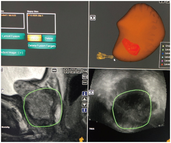
3D US volume is generated with lesion labeled on it (top right panel). US = ultrasound, 3D = three-dimensional
Step 4: Periprostatic Nerve Block
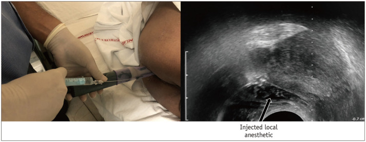
The periprostatic nerve block is provided by injecting the local anesthetic into the echogenic triangle between the base of the prostate and the seminal vesicle. Approximately 5 mL of local anesthetic (1% lignocaine) is injected on each side (15) (Fig. 6).
Fig. 6. Periprostatic nerve block.
Local anesthesia is provided by injecting 1% lignocaine into echogenic triangle between base of prostate and seminal vesicle. Approximately 5 mL is injected on each side.
Step 5: Real-Time Probe Navigation and Biopsy
Real-time sampling is performed with the aid of probe-tracking technology that provides real-time navigation (Figs. 7, 8). For this purpose, the Artemis™ uses angle-sensing position encoders attached to the mechanical arm. A 26-cm-long 18-gauge automatic spring-loaded biopsy gun is used to obtain the tissue cores. For all fusion biopsies, the AUA-SAR recommendation suggests obtaining two spatially distributed samples from the target lesion in addition to systematic 12-core sampling (13). The biopsy samples are separately labeled with location descriptors before dispatching. The fusion biopsy platforms also enable recording the location of biopsy cores for future reference.
Fig. 7. Probe-tracking technology of Artemis™ fusion biopsy system.
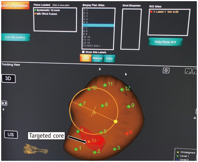
Various cores to be obtained are marked numerically. Nos. 1–12 denote sites for systematic biopsy, whereas no. 13 represents core to be obtained from target lesion (labeled in red), which was mapped onto 3D US volume after fusion with segmented magnetic resonance image. Probe-tracking technology enables real-time navigation of probe towards target site. Artemis™ uses angle-sensing position encoders attached to mechanical arm for probe tracking.
Fig. 8. Real-time TRUS image set for biopsy.
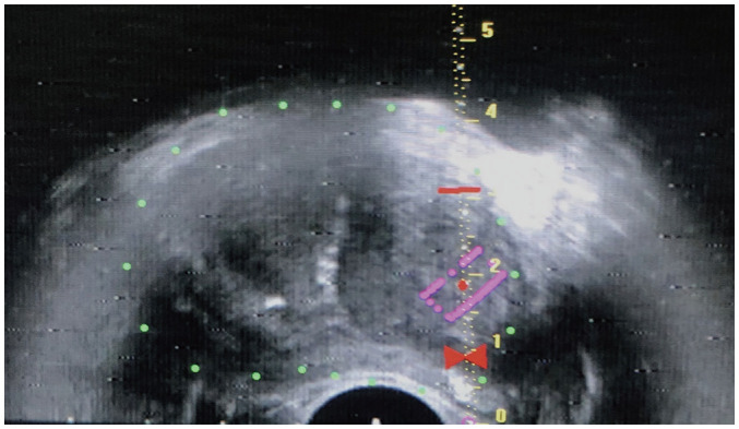
System displays scale and red bowtie. Target lesion is outlined in purple. Bowtie indicates site for needle tip positioning immediately prior to firing. Red horizontal bar is set at 2 cm from bowtie, which is throw-length of biopsy gun. These markers ensure accurate positioning and sampling of target lesion, and prevent overshooting of biopsy needle.
Direct (In-Bore) MRI-Guided Biopsy
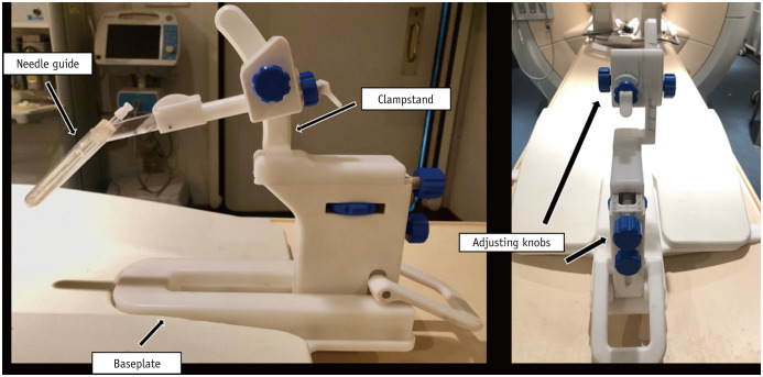
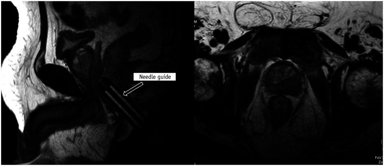
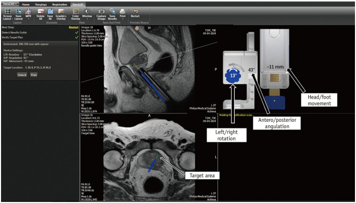
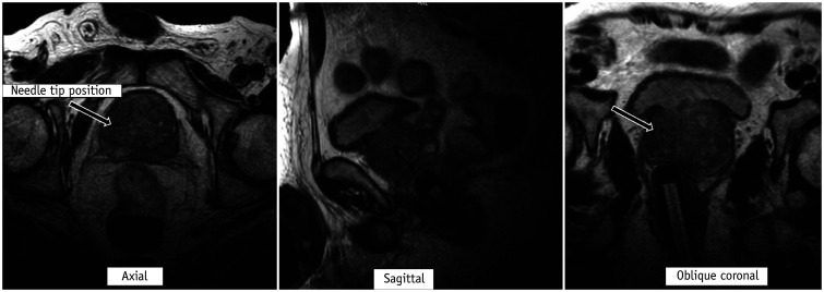
In the direct (in-bore) technique, the radiologist performs the biopsy by direct visualization of the target area. The final position of the needle within the target is confirmed before the biopsy gun is fired. The most common platform used is the DynaTRIM™ (Invivo). The biopsy system consists of a baseplate, clamp stand, adjusting knobs, and a needle sleeve with an attachment site for the needle guide (Fig. 9). The patient is positioned prone on the table, and a phased-array coil is placed on the dorsal aspect. The needle guide is gently introduced into the rectum. A preliminary T2-weighted image is acquired in the axial and sagittal planes to locate the needle guide (Fig. 10). The target area is subsequently marked on the DynaCad™ (Invivo) software, which calculates the coordinates of the target lesion relative to the needle guide (Fig. 11). The needle guide is then positioned in accordance with the values generated by the software by adjusting the knobs for left/right rotation, anteroposterior angulation, and head/foot movement. Once the needle guide is appropriately positioned, an 18-gauge double-shot core-biopsy gun is inserted through the needle guide and triggered. Repeat T2-weighted axial, sagittal, and oblique coronal images parallel to the needle and guide are acquired to confirm correct placement of the needle slot within the target site (Fig. 12). The biopsy gun is then fired and the tissue is sampled. Unlike fusion biopsy, with in-bore biopsy, additional systematic biopsies need not be performed.
Fig. 9. DynaTRIM™ (Invivo) in-bore MRI–guided biopsy system.
System consists of baseplate, clamp stand, adjusting knobs, and needle sleeve with attachment site for needle guide.
Fig. 10. Needle guide localization on preliminary T2-weighted images.
T2-weighted images are acquired in axial and sagittal planes to locate needle guide.
Fig. 11. Biopsy planning on DynaCad™ (Invivo) software, which calculates coordinates of target lesion relative to needle guide.
Software generates values to which knobs are adjusted for left/right rotation, antero/posterior angulation, and head/foot movement so that needle guide is correctly placed for biopsy.
Fig. 12. Confirmation of needle slot placement on T2-weighted images prior to firing.
Once needle guide is appropriately positioned, 18-gauge double-shot core-biopsy gun is inserted through needle guide and triggered. Repeat T2-weighted axial, sagittal, and oblique coronal images parallel to needle and guide are then acquired to confirm correct placement of needle slot (arrow) within target site.
Limitations
Sampling errors can occur in fusion biopsy due to improper segmentation of the gland or lesion or from misregistration during fusion itself. Thus, fusion biopsy requires a relatively steep learning curve (16, 17). Although in-bore MRI-guided biopsy enables accurate needle placement within the target lesion, it is not free of manual errors in interpretation and targeting. This technique also takes a significant toll on precious MRI gantry time, which could be otherwise used for routine diagnostic purposes (18).
CONCLUSION
MRI-guided (fusion and in-bore) biopsies provide a higher detection rate for clinically significant prostate cancer and increase the percentage of positive cores. Although currently used in patients who remain at high clinical suspicion of prostate cancer despite a negative TRUS-guided systematic biopsy, with the increasing use of upfront diagnostic MRI, these biopsies are foreseen to replace standard systematic biopsies. A thorough knowledge of the principles of the various targeted biopsy techniques is essential to obtaining maximum diagnostic yield and performing these procedures safely.
Footnotes
Conflicts of Interest: The authors have no potential conflicts of interest to disclose.
References
- 1.Prostate cancer statistics. World Cancer Research Fund Web site. [Accesse October 8, 2019]. https://www.wcrf.org/dietandcancer/cancer-trends/prostate-cancer-statistics. Published August 22, 2018.
- 2.Bonekamp D, Jacobs MA, El-Khouli R, Stoianovici D, Macura KJ. Advancements in MR imaging of the prostate: from diagnosis to interventions. Radiographics. 2011;31:677–703. doi: 10.1148/rg.313105139. [DOI] [PMC free article] [PubMed] [Google Scholar]
- 3.Schoots IG, Roobol MJ, Nieboer D, Bangma CH, Steyerberg EW, Hunink MG. Magnetic resonance imaging-targeted biopsy may enhance the diagnostic accuracy of significant prostate cancer detection compared to standard transrectal ultrasound-guided biopsy: a systematic review and meta-analysis. Eur Urol. 2015;68:438–450. doi: 10.1016/j.eururo.2014.11.037. [DOI] [PubMed] [Google Scholar]
- 4.Ahmed HU, El-Shater Bosaily A, Brown LC, Gabe R, Kaplan R, Parmar MK, et al. Diagnostic accuracy of multi-parametric MRI and TRUS biopsy in prostate cancer (PROMIS): a paired validating confirmatory study. Lancet. 2017;389:815–822. doi: 10.1016/S0140-6736(16)32401-1. [DOI] [PubMed] [Google Scholar]
- 5.Kasivisvanathan V, Rannikko AS, Borghi M, Panebianco V, Mynderse LA, Vaarala MH, et al. MRI-targeted or standard biopsy for prostate-cancer diagnosis. N Engl J Med. 2018;378:1767–1777. doi: 10.1056/NEJMoa1801993. [DOI] [PMC free article] [PubMed] [Google Scholar]
- 6.Verma S, Choyke PL, Eberhardt SC, Oto A, Tempany CM, Turkbey B, et al. The current state of MR imaging-targeted biopsy techniques for detection of prostate cancer. Radiology. 2017;285:343–356. doi: 10.1148/radiol.2017161684. [DOI] [PMC free article] [PubMed] [Google Scholar]
- 7.Prostate cancer risk management programme (PCRMP): benefits and risks of PSA testing (guidance). GOV.UK Web site. [Accessed October 8, 2019]. https://www.gov.uk/government/publications/prostate-cancer-risk-management-programme-psa-test-benefits-and-risks/prostate-cancer-risk-management-programme-pcrmp-benefits-and-risks-of-psa-testing. Published March 29, 2016.
- 8.Heidenreich A, Bellmunt J, Bolla M, Joniau S, Mason M, Matveev V, et al. EAU guidelines on prostate cancer. Part 1: screening, diagnosis, and treatment of clinically localised disease. Eur Urol. 2011;59:61–71. doi: 10.1016/j.eururo.2010.10.039. [DOI] [PubMed] [Google Scholar]
- 9.Fiuk JV, Holland BC, Dynda DI, Alanee SR. Antibiotics prophylaxis before prostate biopsy in practice: review of online clinical guidelines. Urol Ann. 2015;7:279–280. doi: 10.4103/0974-7796.152954. [DOI] [PMC free article] [PubMed] [Google Scholar]
- 10.Wegelin O, Exterkate L, van der, Kummer JA, Vreuls W, de Bruin PC, et al. The FUTURE trial: a multicenter randomised controlled trial on target biopsy techniques based on magnetic resonance imaging in the diagnosis of prostate cancer in patients with prior negative biopsies. Eur Urol. 2019;75:582–590. doi: 10.1016/j.eururo.2018.11.040. [DOI] [PubMed] [Google Scholar]
- 11.Cool DW, Zhang X, Romagnoli C, Izawa JI, Romano WM, Fenster A. Evaluation of MRI-TRUS fusion versus cognitive registration accuracy for MRI-targeted, TRUS-guided prostate biopsy. AJR Am J Roentgenol. 2015;204:83–91. doi: 10.2214/AJR.14.12681. [DOI] [PubMed] [Google Scholar]
- 12.Yamada Y, Shiraishi T, Ueno A, Ueda T, Fujihara A, Naitoh Y, et al. Magnetic resonance imaging-guided targeted prostate biopsy: comparison between computer-software-based fusion versus cognitive fusion technique in biopsy-naïve patients. Int J Urol. 2020;27:67–71. doi: 10.1111/iju.14127. [DOI] [PubMed] [Google Scholar]
- 13.Rosenkrantz AB, Verma S, Choyke P, Eberhardt SC, Eggener SE, Gaitonde K, et al. Prostate magnetic resonance imaging and magnetic resonance imaging targeted biopsy in patients with a prior negative biopsy: a consensus statement by AUA and SAR. J Urol. 2016;196:1613–1618. doi: 10.1016/j.juro.2016.06.079. [DOI] [PMC free article] [PubMed] [Google Scholar]
- 14.Das CJ, Razik A, Sharma S, Verma S. Prostate biopsy: when and how to perform. Clin Radiol. 2019;74:853–864. doi: 10.1016/j.crad.2019.03.016. [DOI] [PubMed] [Google Scholar]
- 15.Li M, Wang Z, Li H, Yang J, Rao K, Wang T, et al. Local anesthesia for transrectal ultrasound-guided biopsy of the prostate: a meta-analysis. Sci Rep. 2017;7:40421. doi: 10.1038/srep40421. [DOI] [PMC free article] [PubMed] [Google Scholar]
- 16.Gaziev G, Wadhwa K, Barrett T, Koo BC, Gallagher FA, Serrao E, et al. Defining the learning curve for multiparametric magnetic resonance imaging (MRI) of the prostate using MRI-transrectal ultrasonography (TRUS) fusion-guided transperineal prostate biopsies as a validation tool. BJU Int. 2016;117:80–86. doi: 10.1111/bju.12892. [DOI] [PubMed] [Google Scholar]
- 17.Meng X, Rosenkrantz AB, Huang R, Deng FM, Wysock JS, Bjurlin MA, et al. The institutional learning curve of magnetic resonance imaging-ultrasound fusion targeted prostate biopsy: temporal improvements in cancer detection in 4 years. J Urol. 2018;200:1022–1029. doi: 10.1016/j.juro.2018.06.012. [DOI] [PubMed] [Google Scholar]
- 18.Kuru TH, Herden J, Zugor V, Akbarov I, Pfister D, Porres D, et al. How to perform image-guided prostate biopsy: in-bore and fusion approaches. Eur Urol Focus. 2016;2:151–153. doi: 10.1016/j.euf.2016.03.016. [DOI] [PubMed] [Google Scholar]


