

Abstract
Purpose:
When designing a collimation system for pencil beam spot scanning proton therapy, a decision must be made whether or not to rotate, or focus, the collimator to match beamlet deflection as a function of off-axis distance. If the collimator is not focused, the beamlet shape and fluence will vary as a function of off-axis distance due to partial transmission through the collimator. In this work, we quantify the magnitude of these effects and propose a focused dynamic collimation system (DCS) for use in proton therapy spot scanning.
Methods:
This study was done in silico using a model of the Miami Cancer Institute’s (MCI) IBA Proteus Plus system created in Geant4-based TOPAS. The DCS utilizes rectangular nickel trimmers mounted on rotating sliders that move in synchrony with the pencil beam to provide focused collimation at the edge of the target. Using a simplified setup of the DCS, simulations were performed at various off-axis locations corresponding to beam deflection angles ranging from 0° to 2.5°. At each off-axis location, focused (trimmer rotated) and unfocused (trimmer not rotated) simulations were performed. In all simulations, a 4 cm water equivalent thickness range shifter was placed upstream of the collimator, and a voxelized water phantom that scored dose was placed downstream, each with 4 cm airgaps.
Results:
Increasing the beam deflection angle for an unfocused trimmer caused the collimated edge of the beamlet profile to shift 0.08–0.61 mm from the baseline 0° simulation. There was also an increase in low-dose regions on the collimated edge ranging from 14.6% to 192.4%. Lastly, the maximum dose, Dmax, was 0–5% higher for the unfocused simulations. With a focused trimmer design, the profile shift and dose increases were all eliminated.
Conclusions:
We have shown that focusing a collimator in spot scanning proton therapy reduces dose at the collimated edge compared to conventional, unfocused collimation devices and presented a simple, mechanical design for achieving focusing for a range of source-to-collimator distances.
Keywords: beam trimmer, beam trimming, collimation, dose conformity, focus, focused collimation, focused collimators, focusing, lateral conformity, lateral penumbra, Monte Carlo, proton, proton therapy, proton therapy spot scanning, PTSS, spot scanning, TOPAS, trimmer, trimming
1. INTRODUCTION
Proton therapy spot scanning (PTSS) is a technique that uses a magnetically deflected beam to deliver an intensity-modulated dose distribution within a volume.1 Compared to the passive scattering or uniform scanning methods, PTSS does not require patient-specific apertures or compensators, reducing neutron production and integral dose to the patient.2–5 For PTSS delivered without collimation, the achievable lateral dose conformity is dependent on the pencil beam spot size, which can be represented by the standard deviation of the Gaussian function that represents the pencil beam’s lateral intensity distribution in air at isocenter (σair), and the spread of the beam in the patient due to multiple Coulomb scattering.6 At high energies used to treat deep-seated targets, the lateral penumbra at tumor depth is primarily dominated by multiple Coulomb scattering within the patient; at low energies used to treat shallow targets, the lateral penumbra is dominated by σair.7 The σair parameter is further increased by the inclusion of a range shifter to treat superficial targets. Range shifters are necessary for the treatment of very shallow targets because the minimum beam energy for clinical cyclotrons is typically around 70 MeV, which corresponds to a depth in water of 4 cm.
It has been shown that for brain and head and neck sites, a smaller σair leads to a more conformal dose distribution and reduces the normal tissue complication probabilities resulting from proton therapy.8–10 Although achievable spot sizes are shrinking due to improved beam focusing systems, the lateral dose fall-off remains one of the limiting factors impacting dose conformity.11 To achieve clinically acceptable lateral dose conformity for sensitive organs such as the brain, collimating hardware such as a patient-specific aperture or a multi-leaf collimator (MLC) is recommended.12,13 When considering aperture-based systems, the size and shape of the aperture are fixed for each beam angle and therefore collimation is only provided for the largest cross-sectional target area. This leads to the tissue corresponding to some energy layers receiving little to no benefit from the collimation. The use of MLCs in general can solve the problems associated with apertures, such as the ability to collimate individual energy layers, and to remove the need for patient-specific hardware for each beam angle.
A DCS is under development to improve lateral conformity for PTSS. The DCS consists of two pairs of orthogonal nickel collimating trimmers that move in synchrony with the proton pencil beam to intercept and effectively “trim” the pencil beam at the edge of the target (Fig. 1).14 The DCS is designed to be mounted to a proton nozzle, minimizing the air gap between the collimators and the patient. A design question arose during DCS development: At the cost of increasing complexity, should the collimators be focused to match the deflection of the beam for off-axis locations? If the collimator is not focused to match the deflection of the proton pencil beam, a fraction of protons will strike the collimator at the inner face, instead of the top of the collimator (Fig. 2). This leads to partial transmission through the collimator, creating an unwanted transmission tail along the collimated edge and reducing overall achievable conformity. While focused collimation is not novel in radiation therapy, this is the first investigation of the design of a focused collimator for PTSS. Focused collimation has been implemented in some photon therapy systems, including MLCs developed by Siemens and ViewRay that improve the collimation at the leaf ends of a divergent, broad photon beam.15,16 Focused collimation has also been implemented in passively scattered proton beams using divergent-cut apertures and were shown to reduce dose by 9.5% near the field edges compared to normal, flat-cut apertures.17 Although the previous study was done with scattered protons, we expect that focused collimation for PTSS will improve achievable dose conformity based on the same physical and geometric principles. As well, we hope to further investigate these effects on PTSS and extend the principles of the static, focused aperture into a DCS.
Fig. 1.

A model of the dynamic collimation system demonstrating how trimmer blades increase conformity by reducing the lateral penumbra of the beam spot. Trimmers are in gold and the rotation guide is in blue. Orange and blue arrows show direction of trimmer movement.
Fig. 2.

Proton flight paths for an unfocused (left) and focused (right) trimmer setup. The focused trimmer collimates the deflected protons equally, while the unfocused trimmer allows for partial transmission.
We hypothesize that if collimators for PTSS are not focused, the increased dose at the collimated edge and the resulting achievable dose conformity will be inferior to that of a focused collimator. In this work, we quantify the magnitude of these effects and propose a focused DCS that combines the energy layer-specific collimation capability of an MLC-type system and the focused collimation effects of divergent apertures.
2. MATERIALS AND METHODS
2.A. Beam model
This study was done in silico using a model of the Miami Cancer Institute’s (MCI) IBA Proteus Plus system created in Geant4-based TOPAS.18–20 The MCI beamline has a nominal energy range of 70–226.5 MeV with achievable σair ranging from 7 to 3 mm at isocenter, respectively, with scanning magnet source-to-axis distances (SADs) of 219.5 and 182.5 cm. To approximate the behavior of a scanning pencil beam that utilizes sequential steering magnets, a single point source was placed at a virtual SAD of 201 cm, between the physical SADs. A point source with an asymmetric intensity distribution was used to model the off-axis intensity distributions of the proton beamlet. The initial energy and energy spread were modeled using Gaussian functions, and all simulations were compared against commissioning measurements taken at MCI.
2.B. Design of the DCS
There has been some debate in recent literature about the optimal sequence of the collimator and range shifter in the beamline for minimizing lateral penumbra in PTSS. These investigations have shown that the combination of materials and thicknesses of the collimator and range shifter will determine the optimal sequence of these components in the beamline.13,21,22 To determine the optimal order of these components for the DCS, Monte Carlo simulations were performed with a simplified model of the DCS consisting of a 3 cm thick nickel collimator and a 4 cm thick polyethylene range shifter. The two components were separated by an air gap of 4 cm and a voxelized water phantom was placed 4 cm downstream of either the trimmer or the range shifter, depending on the configuration. Simulations were performed in two configurations: COL-DS, in which the collimator was placed downstream of the range shifter [Fig. 3(a)], and COL-US, in which the collimator was placed upstream of the range shifter [Fig. 3(b)]. Both configurations simulated used the same components and airgaps. The COL-DS configuration was shown to reduce lateral penumbra (80–20%) by 15–30% depending on the energy, with lower energies affected more, compared to the COL-US configuration (Fig. 4).23 For this reason, we opted to use the COL-DS configuration in our design.
Fig. 3.

(a) Diagram illustrating the simplified dynamic collimation system configuration (collimator downstream of the range shifter) used in simulations, not to scale. This setup corresponds to the 0 degree baseline simulation. (b) Diagram of collimator upstream configuration.
Fig. 4.
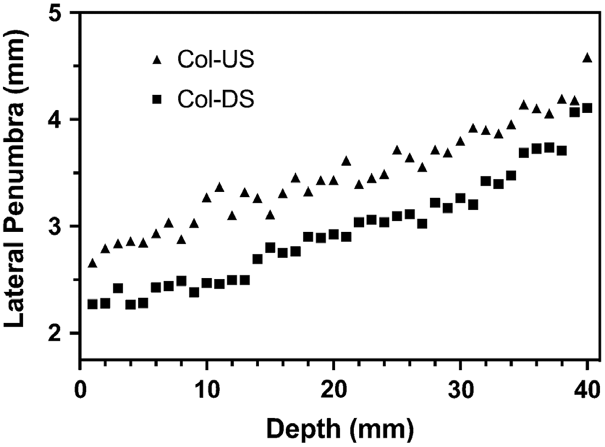
Lateral penumbra from 100 MeV protons at depth for collimator downstream (Col-DS) and collimator upstream (Col-US) configurations.
Regarding material selection for the DCS and range shifter, major considerations were given to minimizing secondary neutron production and the preservation of spot size (σair) for range shifted beams. Nickel was chosen as the collimator material due to its low secondary neutron generation in therapeutic-energy proton beams and widespread availability, reducing the integral dose and likelihood for secondary malignancy.24 Polyethylene was selected for the range shifter because it has the smallest scattering cross section of all the suitable plastics, preserving small spot sizes and dose conformity.25,26
2.C. Unfocused simulations
To evaluate the effect of an unfocused trimmer, a baseline simulation was first performed. The 0° deflection baseline simulation was performed at a beam energy of 100 MeV with the trimmer face aligned 1.5 mm from the beam axis, representing a realistic minimum clinical offset (i.e., maximum trimming). This offset was determined from a separate study and ensures that any small variation in trimmer position will not dramatically impact the resulting beamlet with regards to fluence or beamlet shape. Additional simulations were performed at various off-axis locations corresponding to beam deflection angles ranging from 0° to 2.5°, as listed in Table I. The off-axis locations were calculated based on the physical SAD to the center of the y-axis scanning magnet of the MCI beamline. Although the majority of these simulations were done with a 100 MeV beam, we have included a simulation from a 160 MeV beam for completeness. For simplicity, we grouped the simulations by angle, not off-axis trimmer position, to decouple the simulations from any one proton delivery system. As the trimmer is moved further off-axis, the deflection angle of the beam must be increased since the scanning magnets are at a fixed SAD from isocenter and the magnitude of the deflection angles will vary based on the design of the proton delivery system. As both the beam and the trimmer scan across the field of view (FOV) in synchrony, the central plane of the trimmer face was kept at a constant1.5 mm offset from the beam axis for all off-axis locations (Fig. 5).
Table I.
Beam deflection angles and corresponding off-axis positions for the Y trimmer positions.
| Deflection angle (°) | 0 | 0.25 | 0.5 | 0.75 | 1.0 | 1.25 | 1.5 | 1.75 | 2.0 | 2.25 | 2.5 |
| Y trimmer position (mm) | 1.5 | 9.03 | 16.55 | 24.08 | 31.61 | 39.13 | 46.66 | 54.18 | 61.70 | 69.22 | 76.64 |
Fig. 5.

Diagram of the constant 1.5 mm offset between beamlet center (dashed line) and central plane of trimmer (dot-dash lines). The vertical blue dot-dash lines represent the isocenter axis.
2.D. Focused hardware design
Focusing the DCS trimmers necessitates that they travel in a pendulous arc with a radius that matches the distance from the scanning magnets to the plane of the trimmer, or source-to-collimator distance (SCD). However, developing a prototype that yields such a pendulous motion requires significant custom-ordered parts and the radius of curvature cannot easily be adjusted once manufactured. Rather than moving in a pendulous arc, another option is to develop a system that can rotate the trimmer while simultaneously linearly translating across the FOV to match the beam deflection angle. We chose this option because it can be designed and machined using off-the-shelf hardware and is modular in design such that it can easily be adjusted to match the divergence angle for a wide range of SADs. This is especially important because PTSS systems use two sets of magnets, requiring separate tuning for each pair of trimmers dedicated to each axis.
Our design mounts the trimmers on a rotating platform that is guided by a pair of linear sliders, allowing for simultaneous rotation and translation (Fig. 6). The rotation is achieved via a lever arm attached to the trimmers that follows a custom milled guide rail. The guide rail is a simple straight slot that is milled at a very slight (~0.75°) angle from the horizontal plane. As the trimmer translates linearly, the arm attached to the trimmer follows the path of the guide rail, either slightly raising or lowering the arm, causing the trimmer to rotate. The lever arm is designed such that the pin that follows the guide rail is located at a 45° angle from the axis of rotation, allowing for uniform rotation in both directions. This design allows for easy modification, via adjustment of the angle of the guide rail, to accommodate the beam deflection angles of a wide range of PTSS systems.
Fig. 6.

(a) A single trimmer (gold) mounted on bearings to allow for rotation, shown at four positions to show movement. The lever arm (blue) on top follows the guide rail and rises as it translates from the left to right, rotating the trimmer. Note, the actual DCS will have two trimmers mounted on each axis. (b) Alternate angle of a single trimmer to show context.
Attached to the lever arm pin is a ball bearing to reduce wear from friction with the guide rail. To reduce the chances of the bearing seizing, the guide rail slot was milled 0.1 mm larger than the outer diameter of the bearing. This manufacturing tolerance in the guide rail introduces an error of ±0.1° in the trimmer rotation and is evaluated in the sensitivity analysis section.
2.E. Focused simulations
The focused simulations were identical to the unfocused simulations, except the trimmer was rotated to match the beam deflection angle, as if the trimmer was rotated by the hardware solution described in the previous section. All simulations were completed with the same beam energy of 100 MeV at the same off-axis positions as the unfocused simulations; the dose and standard deviation were scored in an identical voxelized water phantom. A single, 2.5° deflection, 160 MeV proton simulation was also included to show that this behavior continues into higher therapeutic energies.
2.F. Sensitivity analysis
For the previous focused simulations, the trimmer angle perfectly matched the beam deflection angle across the entire range of off-axis points performed. In practice, the trimmer and beam deflection may not be perfectly matched due to the finite manufacturing tolerance and variations in the SCD. Since the trimmer rotation is tuned to match the beam deflection angle for a unique SCD, telescoping proton therapy nozzles to minimize air gap12 will change the SCD, causing the trimmers to become slightly unfocused and possibly reducing the effectiveness of collimation.
To investigate the sensitivity of the focusing on the dose distributions, we varied the SCD by ±10 cm and calculated new trimmer rotation angles across the off-axis points. We chose a 20 cm range because that encompasses any expected variations when using the DCS clinically. Due to the geometry, the sensitivity of the trimmer rotation angle increases as the beam is scanned away from the center, prompting separate sensitivity simulation groups. The first group was for the trimmer at a 1.5° rotation or 46.66 mm from isocenter. At this position, a ±10 cm change in the SCD yielded a ±0.1° change in rotation angle. The second group was for a trimmer at a 2.5° rotation or 76.74 mm from isocenter, yielding a ±0.15° change in rotation angle. For a worst-case scenario, we simulated the same trimmer as the second group, but with the manufacturing tolerance of 0.1° added for a ±0.25° change in rotation angle.
3. RESULTS
3.A. Beam model
The source model was validated against both integral depth dose and lateral profile commissioning measurements made at MCI. For each nominal beam energy, integral depth dose measurements were used to estimate the energy spectrum using iterative methods, where simulations with differing spectra were performed until desired agreement metrics were met and simulation uncertainties were below 0.1%. Metrics of interest were the depth of the Bragg peak, the depth of the distal 80%, and an overall gamma pass rate. For nominal beam energies at MCI ranging from 70 to 160 MeV, the average gamma pass rate was 99.39% at the 1%/1 mm criterion. The asymmetric angular divergence was incorporated into the model through the development of a source that samples from measurements made at isocenter and back-projects to the point source location. Figure 7 illustrates the agreement between this model and the commissioning measurements from MCI.
Fig. 7.

(a) Integral depth dose curves (IDDs) of Monte Carlo model results overlaid with commissioning measurements. (b) 100 MeV lateral intensity X profile at isocenter overlaid with measurements. (c) 100 MeV lateral intensity Y profile at isocenter overlaid with measurements. (d) Y axis lateral agreement at four different planes. (e) Off-axis spot agreement at isocenter.
3.B. Simulations
All simulations yielded a maximum uncertainty of 1.49% at the maximum dose point and all profiles were taken at the proximal surface of a voxelized water phantom with a 0.25 mm dose grid. All dose profiles shown are created by summing the voxels across the center of the beamlet (3 mm band) in the direction opposite of the collimation to improve statistics, unless noted otherwise.
3.C. Unfocused
The most noticeable issue that appeared in the unfocused trimmer simulations was a shift in the collimated edge of the beamlet ranging from 0.08 to 0.61 mm, depending on the beam deflection angle [Figs. 8(a), 8(c) and Table II). In addition, the magnitude of the transmission tail at the collimated edge increased with the deflection angle, from a 14.6% to 192.4% local increase over the baseline simulation (Fig. 9; Table II). Lastly, there was a slight increase in the relative Dmax, up to 5%, for the unfocused simulations as compared to the baseline. These same issues also appear in the 160 MeV simulations, but with some small differences in the magnitudes due to the higher proton energy [Fig. 8(c)].
Fig. 8.

(a) Lateral surface dose profile from a 2.5° unfocused trimmer and a 0° as reference from 100 MeV beam. (b) The same setup, but the trimmer is focused. Error bars shown are one standard deviation. (c) Lateral surface dose profile from a 2.5° unfocused trimmer and a 0° as reference from 160 MeV beam. (d) The same setup, but the trimmer is focused.
Table II.
Beam deflection angles and the resulting beamlet shift and dose tail increase with standard deviation included
| Deflection angle (°) | 0.25 | 0.5 | 0.75 | 1.0 | 1.25 | 1.5 | 1.75 | 2.0 | 2.25 | 2.5 |
| Beamlet shift (mm) | 0.08 | 0.14 | 0.21 | 0.26 | 0.34 | 0.37 | 0.43 | 0.48 | 0.51 | 0.61 |
| Dose tail increase ± SD (%) | 14.6 ± 3.3 | 33.0 ± 7.3 | 50.50 ± 11.1 | 76.20 ± 16.5 | 93.40 ± 20.0 | 102.4 ± 21.5 | 136.3 ± 28.8 | 156.9 ± 33.1 | 177.2 ± 36.9 | 192.4 ± 40.2 |
Fig. 9.

(a) Lateral surface dose profiles of a focused and unfocused 2.5° beam deflection. Profiles are normalized to the unfocused Dmax and shifted to match at the 50% dose line on the collimated edge. (b) Zoomed in profile of the collimated edge with point-to-point dose change plotted. Dotted lines are one standard deviation.
3.D. Focused
Our simulations demonstrated that through focusing the collimator, the lateral dose profile of a 2.5° deflection matched the baseline un-deflected, 0° beam [Figs. 8(b) and 8(d)]. For both energies, the relative beamlet shift, the transmission tail, and the small increase at Dmax were all mitigated when the trimmer was focused. Focusing the collimator was able to achieve these results for all angles of deflection.
3.E. Sensitivity analysis
For all three groups of sensitivity simulations, 1.25° ± 0.1°, 2.5° ± 0.15°, and 2.5° ± 0.25°, there were no statistically significant differences in the dose at the collimated edge (Fig. 10).
Fig. 10.

Sensitivity of focusing on dose distributions. (a) Lateral profiles of a focused 2.5° trimmer and slightly unfocused 2.25° trimmer. (b) Zoomed in profile of the collimated edge. Sensitivity of the focusing design is negligible until surpassing 0.25° angle mismatch. Upper error bars indicate one standard deviation.
4. DISCUSSION
As the beam deflection angle increased for off-axis spots in the unfocused setup, there was an increasing amount of partial transmission due to mismatched beam deflection and trimmer angles. This unwanted transmission through the trimmer caused the penumbra of the dose profile on the trimmed edge to shift away from the collimator [Figs. 8(a) and 8(c)]. Although the maximum distance shifted, 0.6 mm, is small relative to dose voxel resolution, it is on par with spot placement accuracy of spot scanning systems27. If the relative beamlet shift was the only discrepancy in the dose profiles, focusing the collimators may not be necessary. Such behavior could be mitigated by implementing a collimator offset table in the treatment planning software (TPS). The slight increase in Dmax can be attributed to additional and unintentional proton fluence reaching the phantom due to scattering on the inner face of the unfocused trimmer.17 This change in the dose profile could also be accounted for in the TPS with a fluence correction. Although these additions to the TPS could resolve the issues of the relative beamlet shift and change in Dmax, the transmission tail present on the collimated edge cannot be easily accounted for in a pencil beam algorithm. In addition, this transmission tail contributes to the undesired dose outside of the target volume that this collimation approach seeks specifically to minimize. While we chose to simulate a relatively low therapeutic energy because those beamlets would benefit most from collimation in general, it was the higher energy, 160 MeV, where the unfocused trimmer had the largest effect on the transmission tail. The higher energy allowed for more protons to penetrate the face of the trimmer, increasing the partial transmission, resulting in the larger tail.
The combination of all these effects prompted the investigation and design of a focused collimation system. With a focused collimator, all off-axis points and beam deflection angles produce identical beam spots across the entire surface of the phantom [Figs 8(b) and (d)]. While these results have been promising so far, we must also consider the additional complexity associated with the construction of a focusing mechanism. Favorably, sensitivity study simulations revealed that the dose along the collimated edge is not significantly degraded in the presence of realistic manufacturing tolerances and reasonable variation in the SCD. It is not until the mismatched angles surpass ±0.25° that the dose along the collimated edge starts to show differences (Fig. 10).
Proton spot scanning gantries are becoming increasingly compact due to technological improvements and the desire to minimize space occupied in clinics. While compact gantries are logistically beneficial, the scanning magnets must be closer to the patient, shrinking the SADs and causing the beam deflection angles to increase. This is consequential, as we have demonstrated that increasing the deflection angle amplifies the unwanted effects created from an unfocused collimator. This makes the focused design of the DCS even more critical to minimize the lateral penumbra for compact gantries of the future.
5. CONCLUSION
We have shown that focusing a collimator in PTSS reduces dose at the collimated edge compared to conventional, unfocused collimation devices and presented a simple, mechanical design for achieving focusing for a range of SCDs.
ACKNOWLEDGMENTS
Research reported in this manuscript was supported by the National Cancer Institute of the National Institutes of Health under award number R37CA226518. DEH, RTF, and PMH are co-inventors on a patent that has been licensed to IBA.
Contributor Information
Theodore J. Geoghegan, Department of Radiation Oncology, University of Iowa Hospitals and Clinics, 200 Hawkins Drive, Iowa City, IA 52242, USA.
Nicholas P. Nelson, Department of Medical Physics, University of Wisconsin, 1111 Highland Avenue, Madison, WI 53705, USA
Ryan T. Flynn, Department of Radiation Oncology, University of Iowa Hospitals and Clinics, 200 Hawkins Drive, Iowa City, IA 52242, USA
Patrick M. Hill, Department of Human Oncology, University of Wisconsin, 600 Highland Avenue, Madison, WI 53792, USA
Suresh Rana, Department of Radiation Oncology, Miami Cancer Institute, Baptist Health South Florida, 8900 N. Kendall Drive, Miami, FL 33176, USA.
Daniel E. Hyer, Department of Radiation Oncology, University of Iowa Hospitals and Clinics, 200 Hawkins Drive, Iowa City, IA 52242, USA
REFERENCES
- 1.Lomax A Intensity modulation methods for proton radiotherapy. Phys Med Biol. 1999;44:185–205. [DOI] [PubMed] [Google Scholar]
- 2.Arjomandy B, Sahoo N, Zhu XR, et al. An overview of the comprehensive proton therapy machine quality assurance procedures implemented at the University of Texas M. D. Anderson Cancer Center Proton Therapy Center-Houston. Med Phys. 2009;36:2269–2282. [DOI] [PubMed] [Google Scholar]
- 3.Farr JB, Mascia AE, Hsi WC, et al. Clinical characterization of a proton beam continuous uniform scanning system with dose layer stacking. Med Phys. 2008;35:4945–4954. [DOI] [PMC free article] [PubMed] [Google Scholar]
- 4.Brenner DJ, Hall EJ. Secondary neutrons in clinical proton radiotherapy: a charged issue. Radiother Oncol. 2008;86:165–170. [DOI] [PubMed] [Google Scholar]
- 5.Durante M, Loeffler JS. Charged particles in radiation oncology. Nat Rev Clin Oncol. 2010;7:37–43. [DOI] [PubMed] [Google Scholar]
- 6.Safai S, Bortfeld T, Engelsman M. Comparison between the lateral penumbra of a collimated double-scattered beam and uncollimated scanning beam in proton radiotherapy. Phys Med Biol. 2008;53:1729–1750. [DOI] [PubMed] [Google Scholar]
- 7.Engelsman M, Schwarz M, Dong L. Physics controversies in proton therapy. Semin Radiat Oncol. 2013;23:88–96. [DOI] [PubMed] [Google Scholar]
- 8.van de Water TA, Lomax AJ, Bijl HP, Schilstra C, Hug EB, Langendijk JA. Using a reduced spot size for intensity-modulated proton therapy potentially improves salivary gland-sparing in oropharyngeal cancer. Int J Radiat Oncol. 2012;82:e313–e319. [DOI] [PubMed] [Google Scholar]
- 9.Moignier A, Gelover E, Smith BR, et al. Toward improved target conformity for two spot scanning proton therapy delivery systems using dynamic collimation. Med Phys. 2016;43:1421–1427. [DOI] [PMC free article] [PubMed] [Google Scholar]
- 10.Wang D, Dirksen B, Hyer DE, et al. Impact of spot size on plan quality of spot scanning proton radiosurgery for peripheral brain lesions. Med Phys. 2014; 41:121705. [DOI] [PubMed] [Google Scholar]
- 11.Bues M, Newhauser WD, Titt U, Smith AR. Therapeutic step and shoot proton beam spot-scanning with a multi-leaf collimator: a Monte Carlo study. Radiat Prot Dosim. 2005;115:164–169. [DOI] [PubMed] [Google Scholar]
- 12.Daartz J, Bangert M, Buss ıre MR, Engelsman M, Kooy HM. Characterization of a mini-multileaf collimator in a proton beamline. Med Phys. 2009;36(5):1886–1894. [DOI] [PubMed] [Google Scholar]
- 13.Winterhalter C, Lomax A, Oxley D, Weber DC, Safai S. A study of lateral fall-off (penumbra) optimisation for pencil beam scanning (PBS) proton therapy. Phys Med Biol. 2018;63:025022. [DOI] [PubMed] [Google Scholar]
- 14.Hyer DE, Hill PM, Wang D, Smith BR, Flynn RT. A dynamic collimation system for penumbra reduction in spot-scanning proton therapy: proof of concept. Med Phys. 2014;41:091701. [DOI] [PubMed] [Google Scholar]
- 15.Li H, Mutic S, Low D, et al. TH-AB-BRA- 01: a novel doubly-focused multileaf collimator design for mr-guided radiation therapy. Med Phys. 2016;43:3853–3853. [Google Scholar]
- 16.Das IJ, Desobry GE, McNeeley SW, Cheng EC, Schultheiss TE. Beam characteristics of a retrofitted double-focused multileaf collimator. Med Phys. 1998;25:1676–1684. [DOI] [PubMed] [Google Scholar]
- 17.Zhao T, Cai B, Sun B, Grantham K, Mutic S, Klein E. Use of diverging apertures to minimize the edge scatter in passive scattering proton therapy. J Appl Clin Med Phys. 2015;16:367–372. [DOI] [PMC free article] [PubMed] [Google Scholar]
- 18.Perl J, Shin J, Schümann J, Faddegon B, Paganetti H. TOPAS: An innovative proton Monte Carlo platform for research and clinical applications. Med Phys. 2012;39:6818–6837. [DOI] [PMC free article] [PubMed] [Google Scholar]
- 19.Gelover E, Wang D, Hill PM, et al. A method for modeling laterally asymmetric proton beamlets resulting from collimation. Med Phys. 2015;42:1321–1334. [DOI] [PMC free article] [PubMed] [Google Scholar]
- 20.Agostinelli S, Allison J, Amako K. Geant4—a simulation toolkit. Nucl Instrum Methods Phys Res A. 2003;506:250–303. [Google Scholar]
- 21.Bäumer C, Janson M, Timmermann B, Wulff J. Collimated proton pencil-beam scanning for superficial targets: impact of the order of range shifter and aperture. Phys Med Biol. 2018;63:085020. [DOI] [PubMed] [Google Scholar]
- 22.Winterhalter C, Lomax AJ, Oxley D, Weber DC, Safai S. Comment on “Collimated proton pencil-beam scanning for superficial targets: impact of the order of range shifter and aperture”. Phys Med Biol. 2018;63(20):208001. [DOI] [PubMed] [Google Scholar]
- 23.Geoghegan T, Gutierrez A, Flynn R, Wang D, Hyer D. Determining optimal collimator and range shifter sequence for a proton dynamic collimation system. San Antonio, TX: American Association of Physicists in Medicine; 2018. [Google Scholar]
- 24.Smith BR, Hyer DE, Hill PM, Culberson WS. Secondary neutron dose from a dynamic collimation system during intracranial pencil beam scanning proton therapy: a monte carlo investigation. Int J Radiat Oncol Biol Phys. 2019;103:241–250. [DOI] [PubMed] [Google Scholar]
- 25.Kanematsu N, Koba Y, Ogata R. Evaluation of plastic materials for range shifting, range compensation, and solid-phantom dosimetry in carbon-ion radiotherapy. Med Phys. 2013;40:041724. [DOI] [PubMed] [Google Scholar]
- 26.Shen J, Liu W, Anand A, et al. Impact of range shifter material on proton pencil beam spot characteristics. Med Phys. 2015;42:1335–1340. [DOI] [PMC free article] [PubMed] [Google Scholar]
- 27.Li H, Sahoo N, Poenisch F, et al. Use of treatment log files in spot scanning proton therapy as part of patient-specific quality assurance. Med Phys. 2013;40:021703. [DOI] [PMC free article] [PubMed] [Google Scholar]