Abstract
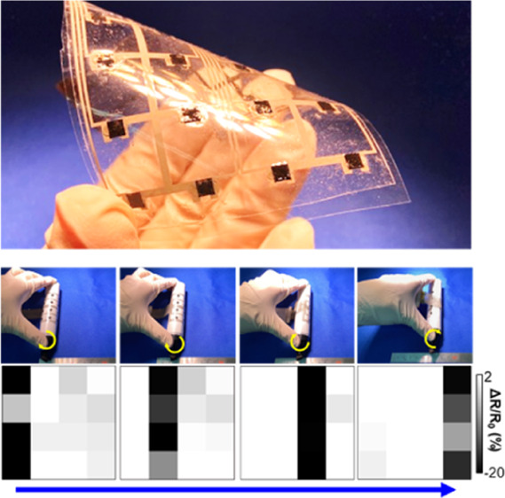
In artificial intelligence and deep learning applications, data collection from a variety of objects is of great interest. One way to support such data collection is to use very thin, mechanically flexible sensor sheets, which can cover an object without altering the original shape. This study proposes a thin, macroscale, flexible, tactile pressure sensor array fabricated by a simple process for economical device applications. Using laser-induced graphene, a transfer process, and a printing method, a relatively stable, reliable, macroscale, thin (∼300 μm), flexible, tactile pressure sensor is realized. The detectable pressure range is about tens to hundreds of kPa. Then, as a proof-of-concept, the uniformity, sensitivity, repeatability, object mapping, finger pressure distribution, and pressure mapping are demonstrated under bending conditions. Although many flexible, tactile pressure sensors have been reported, the proposed structure has the potential for macroscale, thin, flexible, tactile pressure sensor sheets because of the simple and easy fabrication process.
1. Introduction
In the next phase of the “Internet of Things (IoT)” society, the ability to analyze tremendous information data from a variety of objects will be instrumental in predicting trends and enhancing human life. To collect vast amounts of datasets from objects, including nonplanar surfaces, conformally attached macroscale, flexible, and stretchable sensor sheets are of great interest as alternatives to conventional inflexible sensor chips. In fact, mechanically flexible sensors have been proposed for applications of wearable devices,1−6 robotics,7−9 electronic skins,10−18 environmental monitoring,19 and others20−22 by integrating diverse sensors on a film such as tactile pressure, strain, temperature, and chemical sensors. Flexible pressure sensors are important components in many applications. For example, they monitor the pressure distribution in a vehicle that requires human/object motion detection and fluid dynamics such as a car or an airplane.
In these applications, macroscale, flexible sensor sheets, which can cover the large object conformally, are required. However, such devices have size limitations and are cost prohibitive because the fabrication process involves clean room facilities, including a vacuum deposition system.7,10,12,13,15,23 To overcome this challenge, some material transfer, printing, and laser ablation techniques have been proposed to form active materials on a macroscale, flexible film.14,19,24,25 In particular, macroscale, flexible, tactile pressure sensor arrays have been widely developed as resistive, capacitive, and piezoelectric type sensors.8,26−30 Although different potential fabrication processes have been proposed, practical products of macroscale, flexible pressure sensor arrays have not been released to date. Because of this reason, another efficient fabrication process may be required to move forward to building practical device applications.
In this study, we propose a macroscale, very thin, tactile pressure sensor array to monitor the pressure distribution on various surfaces without disturbing the original shape by developing a simple fabrication process. Unlike conventional inflexible sensor chips, which must be affixed to an object with a design change, very thin film-based flexible sensor arrays can be located in any place with a negligible change in shape. This conformal and very thin covering of the sensor over the object is advantageous for applications where a shape change due to attaching a sensor is detrimental. A high-pressure range can be detected although the sensor sheet is thin (∼300 μm). Furthermore, a simple macroscale fabrication method is proposed using a laser-induced graphene (LIG) layer, transfer method, and printing techniques, resulting in good scalability. After characterizing the fundamental tactile pressure properties, finger pressure mapping on a pen and roller pressure distribution monitoring are demonstrated as proofs-of-concept for applications in the rehabilitation field.
2. Results and Discussion
Figure 1 shows the detailed fabrication process and photos of polydimethylsiloxane (PDMS) films with LIG layers and the tactile pressure device laminated by PDMS onto polyethylene terephthalate (PET) films. Because the sensor sheet is very flexible, it can easily cover various surfaces without drastically changing the object shape. It should be noted that large-scale (6 × 6 cm2) sensor sheets can be readily fabricated using simple transfer and screen-printing processes.
Figure 1.
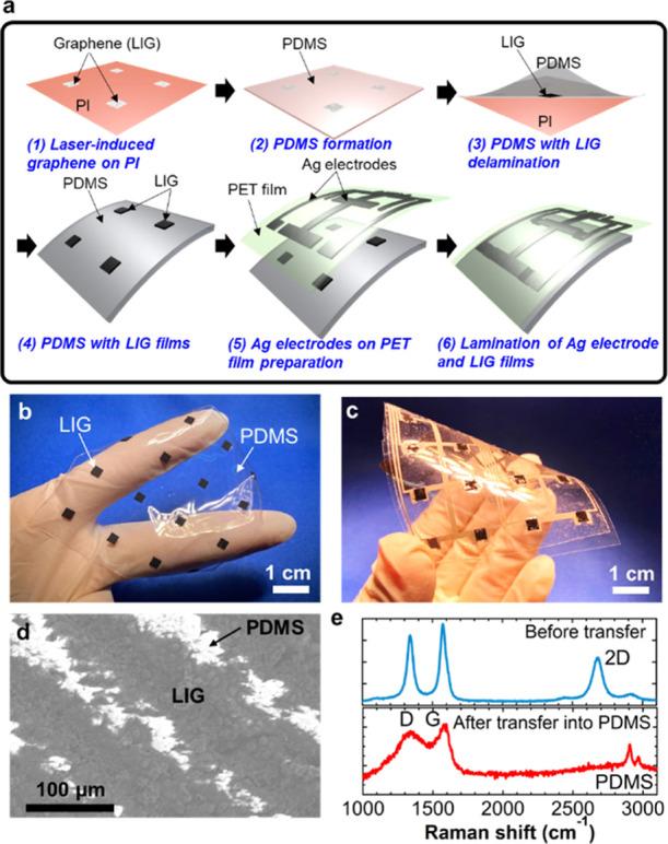
(a) Fabrication process for flexible, tactile pressure sensor sheets. Photos of (b) the LIG-embedded PDMS thin film and (c) the tactile pressure sensor sheet. (d) SEM image of the surface of the LIG-embedded PDMS film. (e) Raman spectroscopy of the LIG film before and after transferring onto PDMS.
2.1. LIG
Scanning electron microscopy (SEM) was used to investigate the LIG film transferred onto the PDMS substrate (Figure 1d). The LIG film had a periodic line structure with a distance of about 100 μm because of the laser scanning step. This structure was a consequence of our laser machine. Because of random LIG formation, the LIG surface after transfer was also rough. The LIG-embedded PDMS surface had a wave structure, where the height of the LIG region in PDMS was higher than that of the non-LIG region. This height difference was about 50 μm. This waved surface realized a contact area difference as a function of the applied pressure. The detailed mechanism is discussed later. For the transferred LIG layer, the Raman spectrum displayed peaks at 1350 cm–1 (D-band) and 1580 cm–1 (G-band) (Figure 1e). Although the distinctive 2D peak (2700 cm–1) of graphene was observed before transferring the LIG films on the polyimide (PI) films onto PDMS, this peak disappeared after transferring, indicating that the transferred LIG layers are randomly located and contain many defects.
2.2. Sensing Mechanism
The contact area dependence corresponding to the contact resistance was used to detect tactile pressure as a resistive-type sensor. Figure 2a schematically depicts images with and without tactile pressure over a sensor. When a pressure is applied to the sensor, the contact area between LIG and Ag electrodes increases because of deformation of the LIG-PDMS layer, which decreases the contact resistance R1 compared to the initial resistance R0 (i.e., R1 < R0). Because the LIG-PDMS surface has a waved structure, the contact area is largely changed by deforming the LIG-PDMS structure. Hence, an applied pressure can be detected by measuring the change in the contact resistance.
Figure 2.
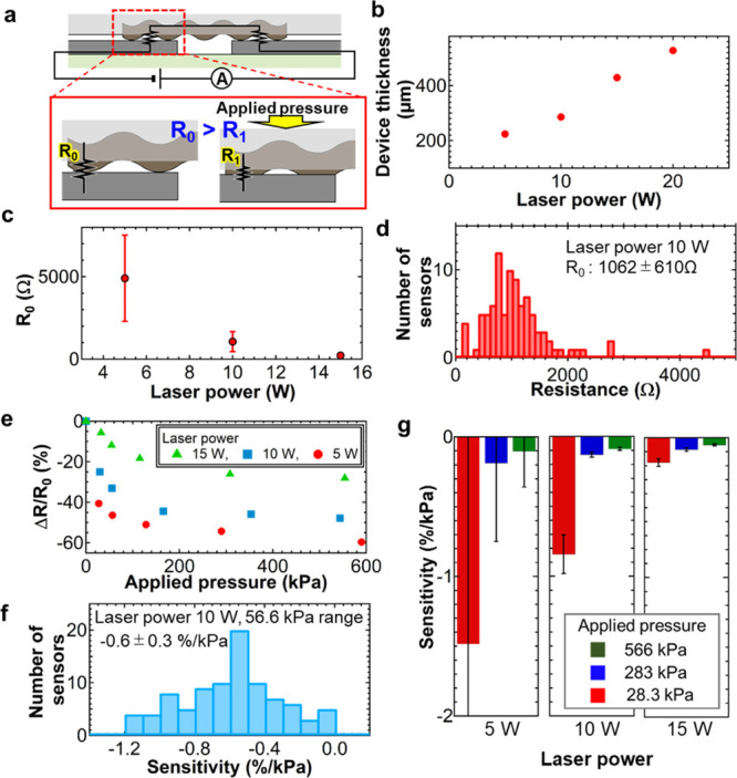
(a) Schematics of the sensing mechanism. (b) Total device thickness and (c) initial resistance of the sensor as functions of the laser power to form the LIG film. (d) Initial sensor resistance distributions at 10 W laser power. (e) Sensor resistance change ratio at different laser powers as a function of the applied pressure. (f) Sensor sensitivity distribution extracted at 56.6 kPa applied pressure at 10 W laser power. (g) Sensitivity at three applied pressure ranges (28.3, 283, and 566 kPa) for three different laser powers.
2.3. Flexible, Tactile Pressure Sensors
The total device thickness is discussed as a function of the laser power for LIG formation. Increasing the laser power increases the LIG thickness. To transfer all LIG layers onto the PDMS film, the film must be thicker than the LIG layer thickness. Consequently, the total device thickness changes linearly with the laser power at a rate of ∼43.5 μm/W starting at 5 W laser power (i.e., ∼215 μm at 10 W and ∼302 μm at 20 W) (Figure 2b).
The initial resistance without applied pressure of the sensor was measured. The initial resistance decreases as the laser power increases because of the change in the thickness of the LIG film (Figure 2c). Importantly, the initial resistance value corresponds to the reproducibility. This is because the resistance value relies on the LIG nanostructure contact in the PDMS film. The probability of poor electrical connections is higher for a low-density LIG film at a low laser power condition. The resistance distribution for the sample at 10 W is 1062 ± 610 Ω (Figure 2d), whereas that at 5 W is 4901 ± 2616 Ω.
To extract the sensor sensitivity at different applied pressures, Figure 2e shows the resistance change ratio, which is expressed by ΔR/R0, where ΔR is the resistance difference between R1 and R0. The resistance largely decreases in the lower pressure range below 100 kPa, regardless of the laser power condition, whereas the resistance change is much smaller in the higher pressure range (i.e., >100 kPa). In this structure, ∼30 kPa is the minimum pressure to detect tactile pressure stably. Because the resistance-change trends in lower and higher pressure ranges differ, the sensitivities extracted by the linear fitting are separated by these ranges (∼28, ∼280, and ∼560 kPa). The sensitivity distribution at 56.6 kPa and 10 W laser power depicts that the sensitivity is about −0.6 ± 0.3%/kPa (Figure 2f). Figure 2g shows the sensitivity for each different laser power and pressure range. The maximum sensitivity achieved by the 5 W laser power is about −1.48%/kPa, whereas that for the 15 W laser condition sample is about −0.177%/kPa in the 28.3 kPa pressure range. Although the device fabricated by 5 W laser power has both better sensitivity and less thickness, its reproducibility and uniformity (sensitivity at 28.3 kPa is −1.48 ± 3.29%/kPa) are not good, whereas the sample at 10 W laser shows −0.18 ± 0.02%/kPa. Reproducibility is an important factor to practically detect the applied pressure distribution. Consequently, the 10 W laser power condition was used for further characteristics and demonstrations. By considering the commercial application, the uniformity even at higher laser power is still not good enough. To improve the uniformity, probably, the formation of LIG layers and the embedding process using PDMS solution should be optimized, which are beyond the scope of this study. Further, it should be noted that because of the use of LIG embedded onto the PDMS film, temperature dependence of the LIG-PDMS resistance was observed. However, to understand the sensing mechanism and characterize the performance precisely, we need further studies for this temperature dependence. Because of this reason, the results about the temperature dependence are not shown in this report.
Figure 3a shows the applied pressure and the corresponding resistance change ratio of the sensor in real-time measurement. A stable resistance change is observed by applying pressure. Hysteresis of the pressure sensor is an important parameter for continuous pressure monitoring. To evaluate the sensor properties, the response time of the pressure sensors was measured by applying a pulse pressure with a duration of about 0.7 s. This speed is a limitation of the equipment used in this study (Figure 3b). Based on the results, the response time is less than 0.1 s. Because of the experimental setup limitation, it can be concluded that the sensor has a capability to measure the pressure with an operating speed of >10 Hz. Although the recovery time after releasing the pressure quickly returns close to the initial value (within 0.1 s), it takes ∼0.9 s to completely restore the initial value. This slow recovery time is attributed to the slow deformation of the PDMS elastomer polymer, which should be improved in the future. However, because the resistance error immediately after applying pressure is small, the pressure distribution can be readily monitored using this simple platform for applications where a small error is acceptable.
Figure 3.
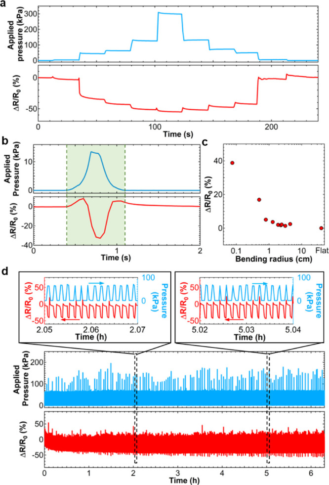
(a) Continuous real-time pressure monitoring and (b) response time measurement results. Top: applied pressure. Bottom: sensor resistance change ratio. (c) Resistance change ratio as a function of the sensor bending radius. (d) Repeatable cycle test for about 4500 cycles for >6 h. Insets show enlarged graphs of the sensor response at the beginning and end of the cycle tests.
Thin, flexible pressure sensors must detect the applied pressure distribution correctly, regardless of the target surface shape. To demonstrate this, a mechanical flexibility test was conducted by measuring the resistance change under bending conditions (Figure 3c). The sensor resistance change is independent of the bending radius above 2 cm. However, the sensor resistance increases gradually below 2 cm radius and drastically at 0.075 cm radius. This is attributed to the reduced contact between LIG and Ag electrodes because of the large lateral deformation of the PDMS film caused by the bending strain. Not only can this sensor cover an object with >2 cm radius, it can also be used for objects with smaller radius up to 0.075 cm, if accurate pressure detection is not required. It should be noted that 0.022 cm radius was also tested. However, after bending the sensor, the sensor resistance does not return to the initial resistance at the flat state, concluding that the sensor cannot be used under such a small radius.
To shed further light on the tactile pressure sensor characteristics, a repeatable cycle test of the pressure application was conducted. Figure 3d shows the results for >4500 cycles at ∼70 kPa for >6 h. The sensor resistance change for the whole cycle test is relatively stable, although a small resistance drift is observed in the first 10 min of the experiment. It should be noted that the applied pressure fluctuates because of the equipment used in this measurement. The resistance change of the sensor also responds to the fluctuating pressure, suggesting that the sensor is stable and can reliably detect multicycle pressure applications. It is worthy to note that the resistance increases right after applying tactile pressure, as clearly shown in Figure 3b,d. This is because the LIG-PDMS layer is also deformed and stretched laterally when the pressure is applied, resulting in an increase in the resistance of LIG-PDMS. At a low applied pressure, most likely, the resistance change of the deformation of LIG-PDMS is large compared to the change of contact resistance between LIG-PDMS and Ag electrodes.
2.4. Demonstrations
As a proof-of-concept of a thin, flexible, tactile pressure sensor, a 4 × 4 sensor array monitored the applied pressure distributions. The resistance changes of all pixels were simultaneously recorded by a data logger. First, objects representing the letters of “O,” “P,” and “U” (Figure 4a) were placed and pressurized over the sensor. Figure 4b displays the pressure mapping of the resistance change ratio for each pressure sensor. The letters are detected along the object shape.
Figure 4.
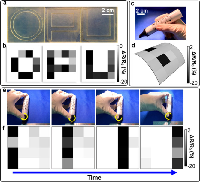
(a) Photos of “O,” “P,” and “U” shape objects. (b) Pressure mapping when the objects in (a) are applied onto the sensor sheet. (c) Photo of a pen conformally covered by the sensor sheet on a hand. (d) Pressure distribution when the pen is held by the hand shown in (c). (e) Photos of the roller with sensor sheets while rolling from the left to right. (f) Pressure mapping when the roller is rolling as shown in (e).
The finger pressure distribution was demonstrated on a pen with a 1.3 cm radius (Figure 4c). Even under a bending condition, the pressure distribution due to fingers is correctly monitored (Figure 4d). Thus, the sensor can quantitatively measure human motion for applications such as rehabilitation.
The final demonstration monitored the pressure distribution of a roller covered by a flexible, tactile pressure sensor sheet while rolling it on a floor (Figure 4e). The pressurized position can be precisely monitored by the sensor sheet without changing the object shape during rolling on a floor (Figure 4f). These findings agree well with the position of the roller movement shown in Figure 4e.
3. Conclusions
This study demonstrates a macroscale, thin, flexible, tactile pressure sensor array formed by LIG/PDMS and Ag electrodes on the PET film. The main advantage is its scalability including the large sheet size and small thickness via a very simple process. Despite a simple fabrication process, the sensor shows a relatively high stability, reproductivity, and reliability in a pressure range from tens to hundreds of kPa. Compared to other flexible, tactile pressure sensor arrays, the sensitivity and flexibility are not remarkable. However, the proposed macroscale simple fabrication process for the planar integrated sensor array may be a possible practical method. Furthermore, by integrating the sensor into an array formation, the applied pressure distribution can be successfully monitored without affecting the object shape. The sensor structure, material, and thickness may be optimized for small pressure ranges less than 10 kPa. For this low-pressure detection, the LIG-PDMS layer should be thinner to obtain more mechanical flexibility. However, to obtain more flexibility, the detectable high-pressure range may be sacrificed. Depending on the application, the film thickness corresponding to the pressure range should be designed. In principle, this sensor platform can be applied to a variety of pressure ranges, which will be the target of a future study. Although many flexible, tactile pressure sensors have been reported, this proposed sensor has great promise for practical applications such as detecting smooth human motion over an object for rehabilitation or monitoring the pressure distribution from a shallow space in an industrial setting.
4. Experimental Section
4.1. Fabrication Process
Figure 1a illustrates the fabrication process. LIG films were formed by carbonizing 125 μm thick PI films using a CO2 laser (Universal VLS2.30, USA) [Fig. 1a(1)].24,25,31 The LIG film size corresponding to one-pixel is 3 × 3 mm2. An uncured PDMS solution (Dow Silicones, SYLGARD184, USA) was poured on the PI films with the LIG films, and the subsequent spin-coating realized a PDMS thin film. The PDMS was cured at 90 °C for 10 min [Figure 1a(2)]. The thinnest PDMS film in this study was ∼200 μm thick because thinner films were torn during the fabrication process. Next, the PDMS was peeled from the PI films to transfer the LIG films onto the PDMS [Figure 1a(3,4)]. This transfer process firmly embedded the LIG film in the PDMS because of random, vertical, and porous LIG films on the PI films. Furthermore, silver (Ag) electrodes were printed and cured at 90 °C on a PET film (38 μm) using screen printing for both interconnections and contacts with the LIG films [Figure 1a(5)]. Finally, the PDMS substrate with the LIG films and the Ag electrodes on the PET film were laminated [Figure 1a(6)]. The adhesion between the PDMS substrate and the PET film was relatively strong because of the conformal covering over the PET film realized by the thin film and the strong adhesion of PDMS on the PET film.
4.2. Demonstration
For the pressure distribution mapping, each resistive tactile pressure sensor was connected to a resistor in series to make a voltage divider. The applied voltage was 2 V. A data logger (LR8401, HIOKI) was used to simultaneously detect the voltage change caused by the sensor resistance change.
Acknowledgments
This work was supported by JST PRESTO (JPMJPR17J5) and JSPS KAKENHI grants (JP17H04926 and JP18H05472).
The authors declare no competing financial interest.
References
- Lee J.; Kwon H.; Seo J.; Shin S.; Koo J. H.; Pang C.; Son S.; Kim J. H.; Jang Y. H.; Kim D. E.; Lee T. Conductive Fiber-Based Ultrasensitive Textile Pressure Sensor for Wearable Electronics. Adv. Mater. 2015, 27, 2433–2439. 10.1002/adma.201500009. [DOI] [PubMed] [Google Scholar]
- Bariya M.; Nyein H. Y. Y.; Javey A. Wearable Sweat Sensors. Nat. Electron. 2018, 1, 160–171. 10.1038/s41928-018-0043-y. [DOI] [Google Scholar]
- Xu K.; Lu Y.; Takei K. Multifunctional Skin-Inspired Flexible Sensor Systems for Wearable Electronics. Adv. Mater. Technol. 2019, 4, 1800628. 10.1002/admt.201800628. [DOI] [Google Scholar]
- Nakata S.; Shiomi M.; Fujita Y.; Arie T.; Akita S.; Takei K. A Wearable pH Sensor with High Sensitivity based on a Flexible Charge-Coupled Device. Nat. Electron. 2018, 1, 596–603. 10.1038/s41928-018-0162-5. [DOI] [Google Scholar]
- Lee H.; Song C.; Hong Y. S.; Kim M. S.; Cho H. R.; Kang T.; Shin K.; Choi S. H.; Hyeon T.; Kim D.-H. Wearable/Disposable Sweat-Based Glucose Monitoring Device With Multistage Transdermal Drug Delivery Module. Sci. Adv. 2017, 3, e1601314 10.1126/sciadv.1601314. [DOI] [PMC free article] [PubMed] [Google Scholar]
- Yamamoto Y.; Harada S.; Yamamoto D.; Honda W.; Arie T.; Akita S.; Takei K. Printed Multifunctional Flexible Device with an Integrated Motion Sensor for Health Care Monitoring. Sci. Adv. 2016, 2, e1601473 10.1126/sciadv.1601473. [DOI] [PMC free article] [PubMed] [Google Scholar]
- Jeong Y.; Park J.; Lee J.; Kim K.; Park I. Ultrathin, Biocompatible, and Flexible Pressure Sensor with a Wide Pressure Range and Its Biomedical Application. ACS Sens. 2020, 5, 481–489. 10.1021/acssensors.9b02260. [DOI] [PubMed] [Google Scholar]
- Boutry C. M.; Negre M.; Jorda M.; Vardoulis O.; Chortos A.; Khatib O.; Bao Z. A Hierarchically Patterned, Bioinspired E-Skin Able to Detect the Direction of Applied Pressure for Robotics. Sci. Robot. 2018, 3, eaau6914 10.1126/scirobotics.aau6914. [DOI] [PubMed] [Google Scholar]
- Yamaguchi T.; Kashiwagi T.; Arie T.; Akita S.; Takei K. Human-Like Electronic Skin-Integrated Soft Robotic Hand. Adv. Intell. Syst. 2019, 1, 1900018. 10.1002/aisy.201900018. [DOI] [Google Scholar]
- Chun S.; Choi I. Y.; Son W.; Bae G. Y.; Lee E. J.; Kwon H.; Jung J.; Kim H. S.; Kim J. K.; Park W. A Highly Sensitive Force Sensor with Fast Response Based on Interlocked Arrays of Indium Tin Oxide Nanosprings toward Human Tactile Perception. Adv. Funct. Mater. 2018, 28, 1804132. 10.1002/adfm.201804132. [DOI] [Google Scholar]
- Park J.; Lee Y.; Hong J.; Lee Y.; Ha M.; Jung Y.; Lim H.; Kim S. Y.; Ko H. Tactile-Direction-Sensitive and Stretchable Electronic Skins Based on Human-Skin-Inspired Interlocked Microstructures. ACS Nano 2014, 8, 12020. 10.1021/nn505953t. [DOI] [PubMed] [Google Scholar]
- Takei K.; Takahashi T.; Ho J. C.; Ko H.; Gillies A. G.; Leu P. W.; Fearing R. S.; Javey A. Nanowire active-matrix circuitry for low-voltage macroscale artificial skin. Nat. Mater. 2010, 9, 821–826. 10.1038/nmat2835. [DOI] [PubMed] [Google Scholar]
- Someya T.; Sekitani T.; Iba S.; Kato Y.; Kawaguchi H.; Sakurai T. A large-area, flexible pressure sensor matrix with organic field-effect transistors for artificial skin applications. Proc. Natl. Acad. Sci. U.S.A. 2004, 101, 9966–9970. 10.1073/pnas.0401918101. [DOI] [PMC free article] [PubMed] [Google Scholar]
- Harada S.; Kanao K.; Yamamoto Y.; Arie T.; Akita S.; Takei K. Fully Printed Flexible Fingerprint-like Three-Axis Tactile and Slip Force and Temperature Sensors for Artificial Skin. ACS Nano 2014, 8, 12851–12857. 10.1021/nn506293y. [DOI] [PubMed] [Google Scholar]
- Kaltenbrunner M.; Sekitani T.; Reeder J.; Yokota T.; Kuribara K.; Tokuhara T.; Drack M.; Schwödiauer R.; Graz I.; Bauer-Gogonea S.; Bauer S.; Someya T. An Ultra-Lightweight Design for Imperceptible Plastic Electronics. Nature 2013, 499, 458–463. 10.1038/nature12314. [DOI] [PubMed] [Google Scholar]
- Kanao K.; Harada S.; Yamamoto Y.; Honda W.; Arie T.; Akita S.; Takei K. Highly selective flexible tactile strain and temperature sensors against substrate bending for an artificial skin. RSC Adv. 2015, 5, 30170–30174. 10.1039/c5ra03110a. [DOI] [Google Scholar]
- Takei K.; Gao W.; Wang C.; Javey A. Physical and Chemical Sensing With Electronic Skin. Proc. IEEE 2019, 107, 2155–2167. 10.1109/jproc.2019.2907317. [DOI] [Google Scholar]
- Ai Y.; Hsu T. H.; Wu D. C.; Lee L.; Chen J.-H.; Chen Y.-Z.; Wu S.-C.; Wu C.; Wang Z. M.; Chueh Y.-L. An Ultrasensitive Flexible Pressure Sensor for Multimodal Wearable Electronic Skins Based on Large-Scale Polystyrene Ball@Reduced Graphene-Oxide Core–Shell Nanoparticlest. J. Mater. Chem. C 2018, 6, 5514–5520. 10.1039/c8tc01153b. [DOI] [Google Scholar]
- Xu K.; Lu Y.; Yamaguchi T.; Arie T.; Akita S.; Takei K. Highly Precise Multifunctional Thermal Management-Based Flexible Sensing Sheets. ACS Nano 2019, 13, 14348–14356. 10.1021/acsnano.9b07805. [DOI] [PubMed] [Google Scholar]
- Le V.-Q.; Do T.-H.; Retamal J. R. D.; Shao P.-W.; Lai Y.-H.; Wu W.-W.; He J.-H.; Chueh Y.-L.; Chu Y.-H. Van der Waals Heteroepitaxial AZO/NiO/AZO/Muscovite (ANA/Muscovite) Transparent Flexible Memristor. Nano Energy 2019, 56, 322–329. 10.1016/j.nanoen.2018.10.042. [DOI] [Google Scholar]
- Chen Y.-Z.; You Y.-T.; Chen P.-J.; Li D.; Su T.-Y.; Lee L.; Shih Y.-C.; Chen C.-W.; Chang C.-C.; Wang Y.-C.; Hong C.-Y.; Wei T.-C.; Ho J. C.; Wei K.-H.; Shen C.-H.; Chueh Y.-L. Environmentally and Mechanically Stable Selenium 1D/2D Hybrid Structures for Broad-Range Photoresponse from Ultraviolet to Infrared Wavelengths. ACS Appl. Mater. Interfaces 2018, 10, 35477–35486. 10.1021/acsami.8b11676. [DOI] [PubMed] [Google Scholar]
- Chen Y.-Z.; Wang S. W.; Su T. Y.; Lee S. H.; Chen C. W.; Yang C. H.; Wang K.; Kuo H. C.; Chueh Y. L. Phase-Engineered Type-II Multimetal-Selenide Heterostructures toward Low-Power Consumption, Flexible, Transparent, and Wide-Spectrum Photoresponse Photodetectors. Small 2018, 14, 1704052. 10.1002/smll.201704052. [DOI] [PubMed] [Google Scholar]
- Tang X.; Wu C.; Gan L.; Zhang T.; Zhou T.; Huang J.; Wang H.; Xie C.; Zeng D. Multilevel Microstructured Flexible Pressure Sensors with Ultrahigh Sensitivity and Ultrawide Pressure Range for Versatile Electronic Skins. Small 2019, 15, e1804559 10.1002/smll.201804559. [DOI] [PubMed] [Google Scholar]
- Ye R.; James D. K.; Tour J. M. Laser-Induced Graphene. Acc. Chem. Res. 2018, 51, 1609–1620. 10.1021/acs.accounts.8b00084. [DOI] [PubMed] [Google Scholar]
- Wakabayashi S.; Yamaguchi T.; Arie T.; Akita S.; Takei K. Out-of-Plane Electric Whiskers Based on Nanocarbon Strain Sensors for Multi-Directional Detection. Carbon 2020, 158, 698–703. 10.1016/j.carbon.2019.11.042. [DOI] [Google Scholar]
- Joo Y.; Byun J.; Seong N.; Ha J.; Kim H.; Kim S.; Kim T.; Im H.; Kim D.; Hong Y. Silver nanowire-embedded PDMS with a multiscale structure for a highly sensitive and robust flexible pressure sensor. Nanoscale 2015, 7, 6208–6215. 10.1039/c5nr00313j. [DOI] [PubMed] [Google Scholar]
- Kim K. K.; Ha I.; Won P.; Seo D. G.; Cho K. J.; Ko S. H. Transparent Wearable Three-Dimensional Touch by Self-Generated Multiscale Structure. Nat. Commun. 2019, 10, 2582. 10.1038/s41467-019-10736-6. [DOI] [PMC free article] [PubMed] [Google Scholar]
- Huang Y.; Fan X.; Chen S. C.; Zhao N. Emerging Technologies of Flexible Pressure Sensors: Materials, Modeling, Devices, and Manufacturing. Adv. Funct. Mater. 2019, 29, 1808509. 10.1002/adfm.201808509. [DOI] [Google Scholar]
- Sarwar M. S.; Dobashi Y.; Preston C.; Wyss J. K. M.; Mirabbasi S.; Madden J. D. W. Bend, Stretch, and Touch: Locating a Finger on an Actively Deformed Transparent Sensor Array. Sci. Adv. 2017, 3, e1602200 10.1126/sciadv.1602200. [DOI] [PMC free article] [PubMed] [Google Scholar]
- Pyo S.; Choi J.; Kim J. Flexible, Transparent, Sensitive, and Crosstalk-Free Capacitive Tactile Sensor Array Based on Graphene Electrodes and Air Dielectric. Adv. Electron. Mater. 2017, 4, 1700427. 10.1002/aelm.201700427. [DOI] [Google Scholar]
- Xu K.; Lu Y.; Honda S.; Arie T.; Akita S.; Takei K. Highly Stable Kirigami-Structured Stretchable Strain Sensors for Perdurable Wearable Electronics. J. Mater. Chem. C 2019, 7, 9609–9617. 10.1039/c9tc01874c. [DOI] [Google Scholar]


