Abstract
The IMPEDE Embolization Plug is a catheter-delivered vascular occlusion device that utilizes a porous shape memory polymer foam as a scaffold for thrombus formation and distal coils to anchor the device within the vessel. In this study, we investigated the biological response of porcine arteries to the IMPEDE device by assessing the extent of healing and overall effectiveness in occluding the vessel at 30, 60, and 90 days. Compared to control devices (Amplatzer Vascular Plug and Nester Embolization Coils), the host response to IMPEDE showed increased cellular infiltration (accommodated by the foam scaffold), which led to advanced healing of the initial thrombus to mature collagenous connective tissue (confirmed by transmission electron microscopy (TEM)). Over time, the host response to the IMPEDE device included degradation of the foam by multinucleated giant cells, which promoted fibrin and polymer degradation and advanced the healing response. Device effectiveness, in terms of vessel occlusion, was evaluated histologically by assessing the degree of recanalization. Although instances of recanalization were often observed at all time points for both control and test articles, the mature connective tissue within the foam scaffold of the IMPEDE devices improved percent vessel occlusion; when recanalization was observed in IMPEDE-treated vessels, channels were exclusively peri-device rather than intradevice, as often observed in the controls, and the vessels mostly remained >75% occluded. Although total vessel occlusion provides the optimal ischemic effect, in cardiovascular pathology, there is a progressive ischemic effect on the downstream vasculature as a vessel narrows. As such, we expect a sustained ischemic therapeutic effect to be observed in vessels greater than 75% occluded. Overall, the current study suggests the IMPEDE device presents advantages over controls by promoting an enhanced degree of healing within the foam scaffold, which decreases the likelihood of intradevice recanalization and ultimately may lead to a sustained ischemic therapeutic effect.
Keywords: occlusive devices, peripheral vascular occlusion, shape memory polymer, recanalization, embolization
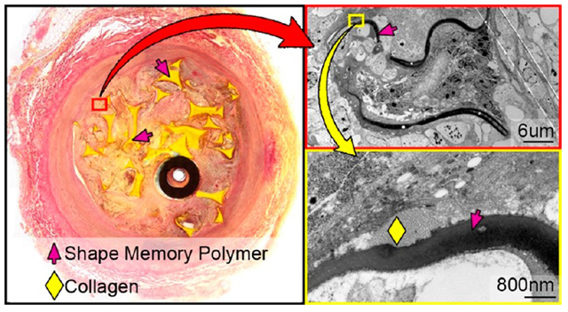
Graphical Abstract
1. INTRODUCTION
Permanent vascular occlusion devices for use in both arteries and veins have become a staple in modern interventional radiology over the past few decades to prevent blood flow into weak or damaged vessels. These devices have been used to treat complications of portal vein hypertension (e.g., gastric varices),1 repair endoleaks associated with the treatment of abdominal aortic aneurysms,2 treat pelvic congestion syndrome,3 and prepare tissue, specifically tumors, for resection through the restriction of blood flow.4
Current vascular occlusion therapy typically involves the delivery of a device to a targeted area that then fills with a thrombus and effectively occludes the vessel. Standard occlusion devices include fibered platinum coils such as Nester Embolization Coils (Cook Medical, Inc., Bloomington, IN) and the Amplatzer Vascular Plug (AVP) developed by AGA Medical, which consists of a single or multilayer nitinol mesh cage delivered via catheter that provides multiple occlusive planes along the length of the device.5
Despite clinical success with standard occlusion devices, certain drawbacks are associated with this technology.6 For example, with regard to treatment of endoleaks following endovascular aneurysm repair, embolization of a single vessel feeding the endoleak sac is often ineffective, and multiple vessels (or the sac itself) must be occluded.2 Additionally, complete arterial embolization using fibered coils may take up to 19 min.7 Another complication of occlusion devices is recanalization, in which flow is restored to the embolized area via formation of endothelial-lined channels. Rates of recanalization within Nester coils can be as high as 20%,8 which can add to procedural costs by requiring additional treatments. Although AVP has reported less recanalization rates than coils alone (<10%, depending on the generation),9 the unpredictability of occlusion times often requires the use of additional devices to achieve reliable occlusion.5 Delivering multiple devices during a single procedure (in combination with the increased time to thrombotic occlusion) not only increases procedural time/cost but also increases patient radiation exposure, as fluoroscopy is necessary to visualize each device deployment and treatment success. These drawbacks demonstrate the need for a new generation of devices that can effectively generate faster and more complete occlusion with fewer devices and with lower rates of subsequent recanalization.
A new entrant into the vascular occlusion device market is the Shape Memory Medical IMPEDE Embolization Plug10 (cleared by the US Food and Drug Administration in June 2018). The IMPEDE device employs a shape memory low-density polyurethane mounted to an anchor coil. The inspiration for the use of a shape memory polymer (SMP) comes from the positive results shown when SMPs were used as embolic devices for stabilizing porcine vascular anomalies and sidewall aneurysms.11-17 In these previous studies of SMP foams deployed within aneurysms, the porous structure of the foam (Figure 1) provided a superior scaffold for optimal infiltration of blood and initial thrombus development. Additionally, the biocompatibility of SMP foams in various animal models has been confirmed by histologic evidence of mature connective tissue within central regions of the foam device.15-17 Previous studies have addressed the biodegradation and degradation products of these and similar materials.15,18,19
Figure 1.
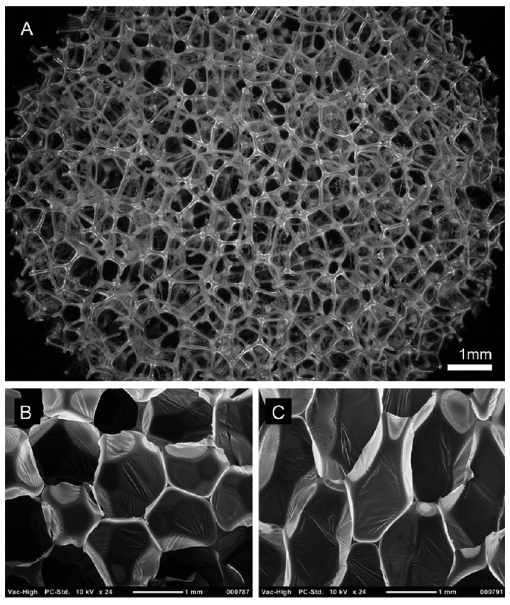
(A) 30× magnification image of foam morphology captured on a Keyence Digital Microscope. Bottom: SEM cross-section images of native SMP foam in (B) horizontal (x–y) and (C) vertical (x–z) planes. Membranes are clearly shown between foam prior to reticulation. Panels B and C are reprinted from Journal of Mechanical Behavior of Biomedical Materials, Volume 40, Rodriguez et al., Reticulation of low density shape memory polymer foam with an in vivo demonstration of vascular occlusion, page 102–114, 2014 (ref 14), with permission from Elsevier.
Once the IMPEDE device is implanted, the anchor coil stabilizes the device in the vessel while the SMP expands to fill the target vessel. The porous morphology of the foam creates a tortuous route through which blood must pass, making recanalization through the center of the device less likely than a coil mass. The porous structure of the expanded polymer also provides substantially greater surface area than bare coils to better initiate thrombus formation and create multiple zones of recirculation and stagnation; this, coupled with the expansile nature of the device, makes full occlusion of a vessel with a single device potentially much easier and faster20 than many other devices. In fact, SMP foams have demonstrated complete hemostasis within as low as 90 s when implanted within porcine arteries.14
The current study compares IMPEDE to two commercially available embolic devices on the market not only to demonstrate the potential to address shortcomings in occlusion device technology but also to provide better care to patients requiring peripheral vessel embolization by having lower rates of recanalization and establishing more rapid healing.
2. MATERIALS AND METHODS
2.1. SMP Foam Synthesis.
Foams used in the IMPEDE devices for this study were synthesized using a three-step gas blowing process discussed previously.21 In short, an isocyanate (NCO) prepolymer was synthesized using appropriate molar concentrations of 1,6-diisocyanatohexane (HDI; TCI America Inc., Portland, OR), N,N′,N′-tetrakis(2-hydroxypropyl)ethylenediamine (HPED; Sigma-Aldrich, Milwaukee, WI), and 2,2′,2″-nitrilotriethanol (TEA, 98%; Alfa Aesar Inc., Ward Hill, MA). The prepolymer is reacted for 2 days with a temperature ramp from room temperature to 50 °C at a rate of 20 °C/h, held isothermally at 50 °C for 16 h, and passively allowed to cool back to room temperature. Then, a second hydroxyl (OH) premix was made with the remaining molar equivalents of HPED and TEA, DI water (>17 M Ω cm purity; Millipore Inc., Temecula, CA), and catalysts T-131 and BL-22 (Evonik Industries, Essen, Germany). For the foaming procedure, the NCO and OH premixes are combined, along with surfactants DC 198 and DC 5943 (Evonik Industries, Essen, Germany) and the physical blowing agent, Enovate (Honeywell, Charlotte, NC). The solution was then mixed in a FlackTek Speedmixer and poured into a mold for foaming. The foam was cured for 5 min at 60 °C before passively cooling to room temperature for further processing. After the foaming process, the foams underwent mechanical reticulation as detailed previously to create pinholes within the membranes of the foams and create an interconnected pore morphology.14 Average transverse pore sizes ranged from 0.85 to 1.50 mm, and average axial pore sizes ranged from 1.30 to 2.20 mm. The average foam density for all foams was 0.02 g/cm3.
After reticulation, foams were cleaned via sonication in HPLC grade water (Pharmco by Greenfield Global, Toronto, Canada), 70% isopropyl alcohol, and >99% isopropyl alcohol (Fisher Scientific, Hampton, NH). After cleaning, the foam samples were submerged in HPLC grade water, frozen in a −20 °C freezer for at least 6 h, and then freeze-dried for a minimum of 24 h at 0.140 mbar and 30 °C. After freeze-drying, the foams were then oven-dried under vacuum at 100 °C for 12 h prior to assembly into final IMPEDE devices. All IMPEDE devices were sterilized via electron beam radiation prior to implantation.
2.2. Animal Study.
All animal studies were conducted according to study protocol LOR020-IS13 at American Preclinical Services (Minneapolis, MN). Three adult porcine specimens at each time point (30, 60, and 90 days; nine specimens total) were implanted with vascular occlusion devices in three vessels each (27 vessels total; Table 1). The test device (IMPEDE) was implanted in two vessels per animal per time point. The third vessel per animal was implanted with one of the control devices (either Nester Embolization Coils or Amplatzer Vascular Plug [AVP]). Fluoroscopy images were captured prior to device implantation, during the implant procedure, and on the day of explantation to visualize vessel occlusion or patency. Animals were sacrificed at 30, 60, and 90 day time points; vessels with implanted devices were harvested and placed in formalin.
Table 1.
Animal Study Setupa
| 30 days |
60 days |
90 days |
||||||
|---|---|---|---|---|---|---|---|---|
| animal | vessel | device | animal | vessel | device | animal | vessel | device |
| 1 | LRA | Impede | 4 | RIMA | Impede | 7 | LIMA | AVP |
| LIMA | Impede | LIMA | Nester | RIMA | Impede | |||
| RIMA | AVP | LRA | Impede | LRA | Impede | |||
| 2 | RRA | AVP | 5 | RIMA | AVP | 8 | LIMA | Impede |
| RIMA | Impede | LIMA | Impede | RIMA | Nester | |||
| LIMA | Impede | RRA | Impede | LRA | Impede | |||
| 3 | RRA | Impede | 6 | LIMA | Impede | 9 | RRA | AVP |
| RIMA | Impede | RIMA | Impede | RIMA | Impede | |||
| LIMA | Nester | LRA | Nester | LIMA | Impede | |||
Vessel abbreviations: LRA, left renal artery; RRA, right renal artery; RIMA, right internal mammary artery; LIMA, left internal mammary artery. Controls: AVP, Amplatzer Vascular Plug; Nester, Nester Embolization Coils. Test Article: Impede, IMPEDE Embolization Plug.
2.3. Pathology Processing.
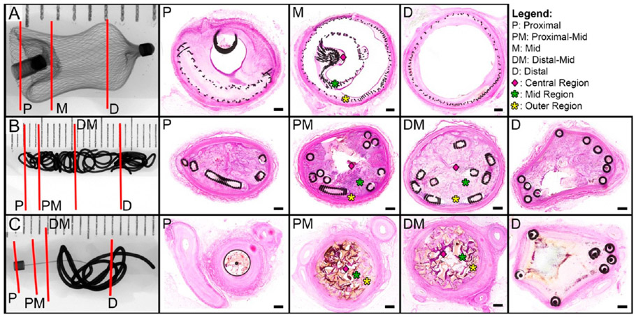
The collected vessels were processed by the Cardiovascular Pathology Laboratory (CVP) at Texas A&M University according to standard operating procedures for dehydration and infiltration of plastic resin (methyl methacrylate). Briefly, each vessel was placed in a labeled container and dehydrated by gradually increasing the concentration of the immersion fluid from 70% to 100% ethyl alcohol. The dehydrated tissues were then introduced to the plastic resin (EXAKT Technovit 7200 Embedding Media), and using the EXAKT Technologies, Inc. 520 Light Polymerization Unit (Oklahoma City, OK), the plastic resin hardened under yellow and blue light for 6 and 12 h, respectively. Radiographs were obtained of each plastic block with the X-Tek Hawk Micro-CT unit (Amherst, NH) and used to plan and denote cut planes to obtain desired slides22 (Figure 2). Thin sections were cut from each block using the EXAKT 300 diamond saw; each section was then microground to approximately 11–67 μm in thickness using the EXAKT 400CS micro grinder and then polished. The slides were stained with Hematoxylin and Eosin (H&E) and oil-immersion scanned with a 100× objective on the Olympus VS120 Virtual Microscope (Tokyo, Japan); slides were analyzed using the OlyVIA iPad application.
Figure 2.
X-ray images of vessels implanted with the three types of occlusion devices tested in this study. (A) Right renal artery implanted with the Amplatzer Vascular Plug for 30 days. (B) Left internal thoracic artery implanted with Nester Embolization Coils for 30 days. (C) Right renal artery implanted with IMPEDE Embolization Plug for 60 days. In the radiographs, red lines indicate the proximal, middle, and distal sections targeted for histological evaluation. Note: For Nester and IMPEDE devices, two middle regions (proximal-mid, distal-mid) were selected for histological evaluation. Corresponding histological cross sections are displayed in order from proximal (left) to distal (right). Middle cross sections were divided into outer (yellow asterisk), mid (green asterisk), and central (pink diamond) regions for additional inflammatory cell count analysis. The scale bar in each histology cross section is 0.4 mm; stain: Hematoxylin and Eosin (H&E).
2.4. Analysis.
2.4.1. Reflow and Occlusion Assessment.
Three to four cross sections of each vessel were analyzed for endothelial-lined intradevice and peri-device vascular channels. To determine the potential for a downstream therapeutic ischemic effect, percent vessel occlusion was estimated by analyzing the histologic cross sections; slides were designated as fully occluded (100% of lumen filled with the device and tissue and no endothelial-lined channels), moderately occluded (75% to <100% lumen filling, some endothelial-lined channels), mildly occluded (50% to <75% lumen filling with some endothelial-lined channels), or minimally occluded (<50% lumen filling and large endothelial-lined channels).
2.4.2. Vessel Wall Assessment.
Vessel injury was assessed by evaluating adventitial changes, disruption of the internal and external elastic lamina (IEL and EEL), and medial injury for each vessel. Changes were described as minimal (involving <5% of the vessel circumference), mild (5% to <25%), moderate (25% to <50%), marked (≥50%), or no changes (0% of vessel circumference affected). Similar regions of each device (proximal, mid, distal) were compared to assess the effect of different components of the device on the vessel wall (e.g., anchor coil vs polymer of IMPEDE device).
2.4.3. Cellular Response to Device.
The cellular response to the implanted device was evaluated by identifying cell types present regionally throughout the vessel lumen. Erythrocytes were counted to assess the degree of thrombus formation present from the time of initial implantation. The degree of an acute inflammatory response was assessed by counting the number of neutrophils, eosinophils, lymphocytes, and plasma cells. The initial transition past acute inflammation and the first indication of a healing response was associated mostly with the progressive breakdown of the initial thrombus from the implant within the vessel lumen; this was analyzed by counting macrophages, macrophages phagocytizing erythrocytes (i.e., erythrophagocytosis), and hemosiderin-laden macrophages. Further, additional cues for advanced healing were assessed by counting the fibroblasts and fibrocytes present throughout the intralumenal device and vessel wall. To accomplish the comprehensive cell assessment, vessel cross sections were divided into central, mid, and outer regions (Figure 2), and 100 cells in each region were classified by cell type as mentioned previously. At least one slide from each vessel was selected for this morphometric analysis; optimal morphometric analysis was performed on sections where the majority of the lumen contains the device with minimal effacement due to active blood dissection.
2.4.4. Healing Assessment.
The substrate within each region (outer, mid, inner) of the device was distinguished as fibrin, loose collagen (loose cellular connective tissue), dense collagen (dense cellular connective tissue), or an admixture of the three. Taking into consideration the cellular response and the contents of the substrate, an overall healing score (Table 2) was assigned to the outer, mid, and inner regions within each slide.
Table 2.
Healing Score
| 0 | healed | fibrocytes and collagen, multinucleated giant cells; capillaries; dense cellular connective tissue (dominant) |
| 1 | midstage healing to healed | capillaries; multinucleated giant cells; islands of loose matrix and dense collagen |
| 2 | midstage healing | macrophages (hemosiderin laden, cellular and substrate debris), fibroblasts, lymphocytes and admixture substrate (collagen and isolated fibrin fragments), multinucleated giant cells; admixture of neovascular buds and capillaries (dominant); loose cellular connective tissue |
| 3 | early to midstage healing | neovascular buds and capillaries; multinucleated giant cells; admixture of loose collagen (dominant) and fibrin |
| 4 | early stage healing | macrophages (erythrophagocytosis, cellular and substrate debris phagocytosis), fibroblasts, neutrophils, eosinophils, lymphocytes, multinucleated giant cells, plasma cells; neovascular buds; granulation tissue; admixture of fibrin and loose collagen |
| 5 | residual blood to early stage healing | neovascular buds; admixture of fibrin (dominant) and loose collagen |
| 6 | residual blood | cells and fibrin/protein; no vasculature; fibrin, no collagen |
One middle cross section of the IMPEDE device from each time point (three slides total) was examined with transmission electron microscopy (TEM) to verify tinctorial and morphologic characteristics observed via light microscopy. TEM processing and analysis was performed at Texas Heart Institute Cardiovascular Pathology Laboratory (Houston, TX). After identification of targeted regions of the extracellular matrix (ECM), the plastic-embedded sections were remounted to accommodate ultrathin ~80 Å sectioning. Ultrathin sections were stained with lead citrate and uranyl acetate and then viewed with TEM. ECM morphology was evaluated in outer, mid, and inner regions of the vessel lumen to validate light microscopy findings and support the overall healing assessment.
2.4.5. Polymer Degradation Analysis.
To understand toxicity thresholds and device lifetime, the in vivo degradation of the shape memory polymer foam was analyzed. The shape memory polymer foam is comprised of two basic units: struts and membranes. Membranes are thin sections of the polymer connected between strut edges and vertices. The membranes are typically 10 μm in thickness and, due to the reticulation and cleaning process, show various morphologies in vivo. The struts are thicker components of the foam (typically 100 μm on the cross section) and serve as the structural backbone. Through various benchtop studies, we have determined that membranes and struts account for approximately 13% and 87% of the foam mass, respectively. As such, there are two components to the degradation calculation: relative membrane loss and relative strut surface area loss.
The degradation of the polymer within each IMPEDE device was analyzed using the high-resolution digital scans on the OlyVIA application. All images in OlyVIA were analyzed with the scale bar function on. Whenever possible, one slide was selected from each region of the vessel (proximal, mid, distal; maximum of three slides per vessel) for degradation analysis. Note that, in many cases, the proximal or distal images were not feasible for the evaluation due to the location of the section (i.e., section did not intersect the foam portion of the device). All sections available for the evaluation were used for every explant. An image (or multiple images if necessary) of the entire slide was captured for both relative membrane loss analysis and relative strut loss analysis.
2.4.5.1. Measured Strut Loss Evaluation.
Using the Cell Counter Tool in ImageJ (National Institutes of Health, Bethesda, MD), the total number of struts in each section was counted. Within each slide, struts selected for degradation evaluation were chosen by dividing the section into a grid of nine squares; three struts were selected from each grid square, with one additional strut selected from the outer, mid, and inner positions of the slide, for a total of 30 struts for degradation analysis. Of note, a random generator was not used to select the struts for the evaluation given the small number of struts within each square. Selected struts were imaged in OlyVIA at high magnification and resolution. The images were imported into ImageJ; the strut was outlined with the freeform tool along the visible edges of the strut, and the total measured strut area was recorded. If degradation regions were visible/identified along the surface of the strut (i.e., areas of scalloped edges or divots), these areas were measured by assuming a linear edge along the strut and tracing the divot. The degradation regions were summed for each strut, and this value was added to the measured strut area value to determine a total strut area (eq 1). The measured strut loss was then calculated by dividing the total measured degradation area by the total strut area (eq 2). This process was repeated for each of the struts from the chosen histological section. Additionally, the number of degradation regions per strut, as well as the average area of each degradation region, were tracked for all sections evaluated.
| (1) |
| (2) |
2.4.5.2. Relative Membrane Loss Evaluation.
Membranes were divided into three groups for the purpose of quantitative and qualitative analysis: intact/connected membranes, broken/separated membranes, and missing membranes. These three groups were used to identify a relative membrane loss (missing membranes divided by the total number of assumed membranes; eq 3) and showed the relative progression of degradation at each time point qualitatively. Using the overall image of the section previously obtained for relative strut loss evaluation, the Cell Counter tool in ImageJ was used to count the intact membranes remaining in the section, the broken/isolated membranes, and the “missing membranes” (a count based on the assumption of previous membranes at strut vertices and previous connections between adjacent struts). This evaluation was performed for all sections identified as usable for degradation analysis. An average relative membrane loss was determined for each time point.
| (3) |
2.4.5.3. Total Degradation Calculation.
On the basis of the aforementioned relationship between membrane and strut mass percentage to determine total foam mass (13% membranes; 87% struts), the relative membrane loss and the relative strut loss were weighted accordingly for each time point to determine the total degradation (in terms of percent mass loss) for the foams within each vessel (eq 4).
| (4) |
3. RESULTS
3.1. Reflow and Percent Occlusion.
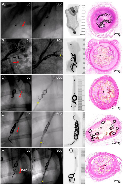
The fluoroscopic evaluation on the day of device implantation revealed full occlusion of all vessels treated (Figure 3). The fluoroscopic evaluation was repeated on the day of vessel explantation to determine if the vessel remained occluded or if recanalization had occurred. At 30 days postimplant, only one vessel (1/9; 11.1%) remained fully occluded (treated with AVP; Figure 3A); the remaining eight vessels at this time point (six treated with IMPEDE, one with AVP, and one with Nester) exhibited reflow (IMPEDE, Figure 3B). At 60 days postimplant, three vessels (3/9, 33.3%) remained fully occluded (treated with IMPEDE; see histologic cross sections in Figure 2C); the remaining six vessels (three IMPEDE [Figure 3C], two Nester [Figure 3D], and one AVP) exhibited reflow. Finally, at 90 days, only two vessels (2/9, 22.2%), both treated with the IMPEDE device, were fully occluded. All other vessels at this time point exhibited contrast downstream (Figure 3E, IMPEDE).
Figure 3.
Fluoroscopic, radiographic, and histology views of vessels implanted with an Amplatzer Vascular Plug occlusion device at 30 days (A), IMPEDE Embolization Plug at 30 days (B) and 60 days (C), Nester Embolization Coils at 60 days (D), and IMPEDE Embolization Plug at 90 days (E). Red arrows indicate the direction of blood flow. Yellow asterisk indicates contrast downstream, indicative of recanalization. X-ray images are oriented with the proximal end (i.e., upstream) of the devices at the top of the image.
Histological cross sections at multiple regions throughout the vessel were used to estimate the maximum percent occlusion of each vessel (Figure 4). While only 6 out of 27 vessels throughout the study exhibited 100% occlusion on the day of the explant, 16 out of 27 vessels remained >75% occluded. There were only 5 vessels (2 at 60 days and 3 at 90 days) that had maximum percent occlusion between 50% and 75% based on the histological cross-sectional area of thrombus within the vessel lumen. IMPEDE was the only device type within this study to achieve 100% occlusion at 60 and 90 days; however, one vessel implanted with IMPEDE at 90 days had a maximum percent occlusion between 50% and 75%.
Figure 4.
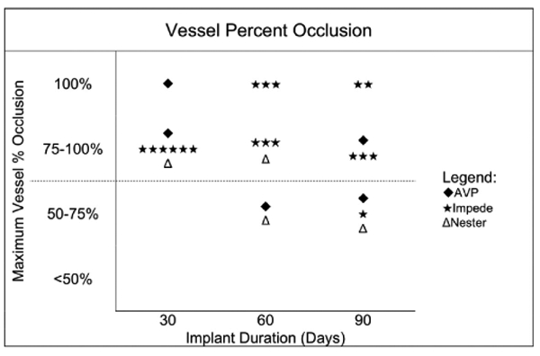
Maximum vessel percent occlusion for each device type at each time point. Each vessel is only represented once in this chart. The dotted line indicates the occlusion threshold for a potential downstream ischemic therapeutic effect.
Reflow was also assessed histologically by observing the presence and location of endothelial-lined channels. The IMPEDE vessels with reflow histologically exhibited endothelial-lined channels that were exclusively peri-device (i.e., between outer region and vessel intima; Figure 3B,C,E). In contrast, the control devices exhibited intradevice recanalization (Figures 2A and 3D) and/or peri-device channels.
3.2. Vessel Wall Assessment.
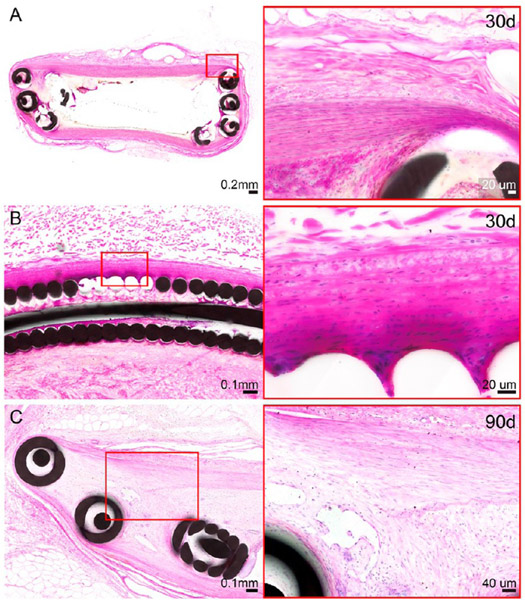
The only moderate to marked changes to the vessel wall were noted in the distal cross sections through the anchoring coils of IMPEDE devices: one cross section of IMPEDE anchoring coils exhibited changes to >50% of the adventitia at the 30 day time point (Figure 5A). Additionally, two vessels implanted with IMPEDE (one at 30 days and one at 90 days) exhibited moderate medial injury in the cross section through the distal anchoring coils, including moderate disruption of the internal elastic lamina (Figure 5B,C). The remaining cross sections of the test article and control vessels across all time points exhibited minimal, mild, or no changes to the adventitia and media (i.e., changes were limited to <25% of the vessel circumference).
Figure 5.
H&E-stained histologic cross sections of distal anchoring coils of the IMPEDE device with changes noted to the vessel wall. Changes to the adventitia were noted in one vessel (right internal thoracic artery) at the 30 day time point (A). These adventitial changes are characterized as a transition from the initial implant injury to early stage healing. Medial injury was noted for >25% of the vessel circumference for two vessels (right internal thoracic artery at the 30 day time point [B] and left renal artery at the 90 day time point [C]). These changes include moderate attenuation of the media, with occasional disruption of the internal elastic lamina; these changes were multifocal with no indication of transmural injury.
3.3. Cellular Response to Device.
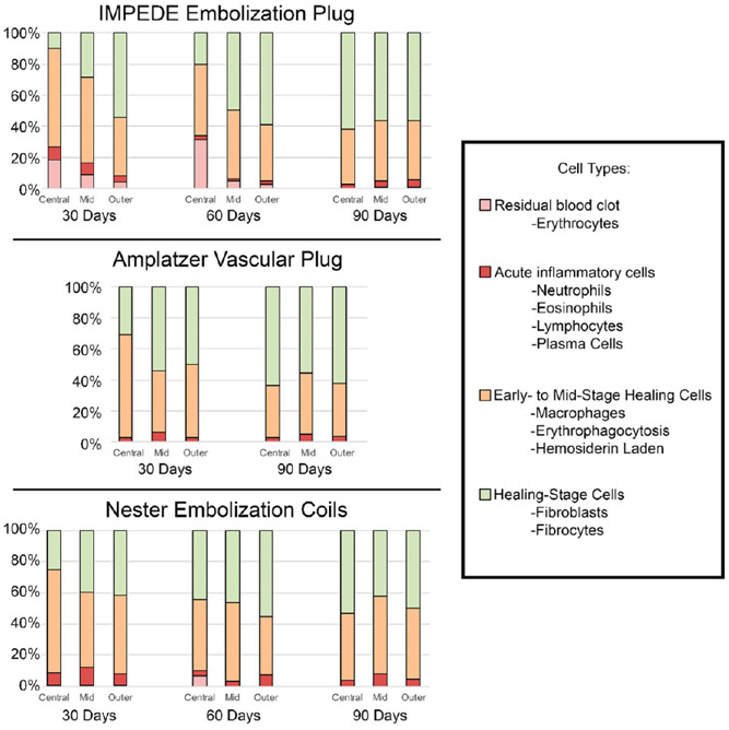
The average percentage of cell types counted within each region (central, mid, outer) of each device are displayed in Figure 6 (see Table S1 for complete data). Of note: numbers of multinucleated giant cells were not quantitatively assessed due to the characteristic lining of these cells around the polymer; the multinucleated aggregate surrounding the polymer did not lend itself to reliable quantitation. However, multinucleated giant cell presence was addressed qualitatively and is reflected in the healing score assigned (defined in Table 2).
Figure 6.
Average percentage of cell types within central, mid, and outer regions of vessel cross sections treated with IMPEDE, AVP, and Nester devices. Note: The vessel implanted with AVP at 60 days was not scored due to the presence of extensive intradevice vascular channels. Additionally, multinucleated giant cells were assessed qualitatively and are not reflected in this figure; however, they are reflected in the healing score assigned (defined in Table 2).
Within the central region of vessels implanted with IMPEDE, the average percentage of cells present on each histological cross section associated with acute inflammation decreased from 30 to 60 days and leveled off at 90 days. In this same region, the average percentage of macrophages (including instances of erythrophagocytosis and hemosiderin-laden macrophages) also consistently decreased from 30 to 90 days but remained more prevalent on the slide than acute inflammatory cells. Finally, the percentage of cells associated with healing (fibroblasts and fibrocytes) located within the central region of the IMPEDE device increased over time. The outer region of IMPEDE vessels exhibited similar percentages of cell types across all time points.
At the 60 day time point, there was only one vessel implanted with the AVP device; this vessel exhibited extensive intravascular recanalization, and there was not enough substrate within the lumen to assess for cellular content in the outer, mid, and inner regions. However, the vessels implanted with AVP at the 30 and 90 day time points were able to be evaluated for a cellular response in at least one vessel at each time point. In vessels implanted with AVP at the 30 and 90 day time points, residual erythrocytes were not noted. The total number of acute inflammatory cells remained less than 6.5% of cells counted in all regions evaluated. Macrophages were dominant in the central region at 30 days and then accounted for <50% of the cell types at 90 days. The total number of fibroblasts/fibrocytes increased within the central region from 30 to 90 days and accounted for >50% of the cells in all other regions.
The central, mid, and outer regions of vessels implanted with Nester exhibited similar amounts of total acute inflammatory cells as the other device types. The average macrophage count remained mostly consistent across all time points, except at 30 days where the central region exhibited slightly increased total macrophages. Finally, the fibroblast/fibrocyte count within the central region doubled by 90 days (compared to the count at 30 days) and accounted for approximately 40–55% of cells counted in other regions at all time points.
3.4. Healing Response.
Overall, the vessels implanted with the IMPEDE device exhibited more progressive healing in the outer third of the vessel compared to the inner two-thirds at all time points, indicated by a lower healing score in the outer region (Figure 7). The central region of the vessels implanted with IMPEDE at 30 days was primarily in transition from residual blood within the implant to early stage healing (average healing score of 4.7 ± 0.8); by 90 days, the central region was transitioning from early to midstage healing (2.8 ± 0.7). In contrast, the outer region of the device reached early to midstage healing (2.3 ± 0.5) by 30 days and was in midstage healing to healed stages by 90 days (1.5 ± 0.5). The vessels implanted with Nester exhibited a similar trend of resolution of the initial thrombus from the implant toward early to midstage healing. The vessel implanted with AVP also exhibited better healing scores (i.e., lower scores) in all regions at 90 days (compared to 30 days); further, at 90 days, the AVP vessel exhibited the greatest degree of healing within the inner region of all vessels evaluated (1.5 ± 0.7).
Figure 7.
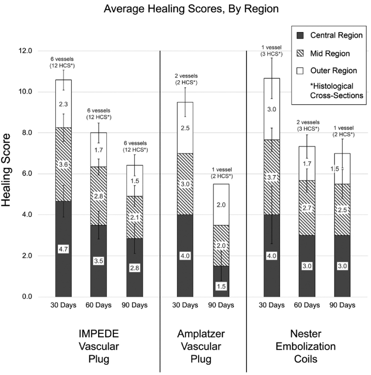
Average healing scores of vessels implanted with IMPEDE, AVP, and Nester devices across all time points. Note: The vessel implanted with AVP at 60 days was not scored due to the presence of extensive intradevice vascular channels and the lack of sufficient substrate. Healing scores are defined in Table 2.
TEM evaluation of the ECM was performed to verify the light microscopy findings of vessels implanted with IMPEDE. The ECM at earlier time points (i.e., at 30 and 60 days) comprise a greater degree of fibrin, whereas the ECM at the later time point (90 days) shows greater deposition of more mature collagen. TEM of the substrate (Figure 8) verifies the trend of increased infiltration of mature collagen within the central region of the lumen at 60 and 90 days, which correlates positively with the defined healing scores. These results indicate that the overall healing process (including the progression from fibrin to lose collagen and finally to dense collagen) occurs both spatially and temporally, which is consistent with studies of other types of tissues23,24 as well as previous studies of foam-treated aneurysms.15,16
Figure 8.
Selected TEM of the extracellular matrix (of vessels implanted with IMPEDE) used to validate tissue healing scores. There is less fibrin and more mature collagen seen at later time points and less fibrin seen in the outer regions compared to the inner regions of each vessel. Key: red asterisk, fibrin; yellow asterisk, loose collagen; green asterisk, dense collagen; diamond, polymer.
3.5. In Vivo Degradation Results.
The polymer foam within the IMPEDE devices was predominately within a connective tissue substrate with direct apposition of multinucleated giant cells to the surface of the polymer (Figure 9). Within these foci, the polymer adjacent to the multinucleated giant cell was undergoing minimal, active degradation.
Figure 9.
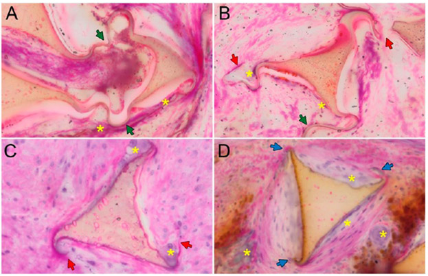
Polymer degradation in vivo. (A) Polymer foam strut at 30 days exhibiting no degradation: foam shows intact membranes (green arrowheads); no clear scalloping of edges. (B) Polymer foam strut at 30 days with intact membranes and cleaved membranes (red arrowheads), minimal scalloping along edges. (C) At 60 days, the polymer foam strut shows cleaved membranes and clear scalloping along the edges. (D) By 90 days, the foam is missing membranes on all vertices (blue arrowheads) and exhibits more distinct scalloping. Key: green arrowhead, intact membranes; red arrowhead, cleaved membranes; blue arrowhead, missing membranes; yellow asterisk, multinucleated giant cells.
The analysis of the cross-sectional area of the polymer foam revealed a steady increase in the mass loss of the shape memory polymer foam at each subsequent time point, indicative of a steady rate of degradation in vivo (Table 3). The mass loss approximately tripled by the 90 day time point; the relative membrane loss accounted for a majority of the mass loss at each time point. This is due to the large surface area and low volume presence of the membranes, coupled with their tendency to break apart from mechanical stress/biological interactions. Furthermore, the average size of the struts did not vary significantly between the 30, 60, and 90 day groups, giving no indication of the total surface erosion of the struts.
Table 3.
Degradation
| time point (days) |
total degradation (mass loss percentage) |
relative membrane loss (missing membrane percentage) |
average foam strut count |
qualitative assessment |
|---|---|---|---|---|
| 30 (n = 11a) | 3.22 ± 3.90 | 21.3 ± 7.05 | 62.7 ± 12.9 | membranes mostly broken/separated some membranes isolated due to cellular activity isolated degradation regions along strut edges |
| 60 (n = 12a) | 6.91 ± 4.97 | 48.4 ± 8.53 | 63.7 ± 11.4 | membranes are mostly degraded with the rest broken and/or isolated due to cellular activity or tissue ingrowth increased number of degradation regions per strut as well as increased number of struts with degradation regions |
| 90 (n = 17a) | 9.42 ± 7.05 | 64.3 ± 13.9 | 59.1 ± 12.9 | majority of membranes are degraded; remaining are broken or isolated continued increase in number of degradation regions and number of struts presenting degradation (scalloping pattern) |
The “n” described in this table reflects the number of slides analyzed per time point. Multiple slides were analyzed per vessel.
4. DISCUSSION
4.1. Host Response to Implanted Materials.
The host response to an intravascular device may involve many stages, such as the primary injury at implantation, blood–material interactions, formation of a provisional matrix, acute inflammation, chronic inflammation, granulation tissue development, foreign body reaction, and fibrosis.25 Injury occurring at implantation initiates the host inflammatory response, and this combined with the clotting cascade contributes to the initial thrombus/blood clot formation (i.e., provisional matrix) at the interface of the host tissue with the biomaterial. This is followed by acute inflammation, characterized by polymorphonuclear cells (PMNs), specifically neutrophils. Neutrophils remove necrotic tissue and residual debris and begin to secrete chemotactic molecules to recruit lymphocytes and macrophages around 48 h after the initial injury.26 A sustained acute inflammatory reaction (represented by continued neutrophil activity at later time points) potentially indicates an undesirable response and could lead to sustained host tissue damage and tissue necrosis. Ideally, the host response to implantable devices begins with an initial acute inflammatory response with transition to an early healing response over 7 to 30 days. The early healing phase is characterized by a progressive reduction in the acute inflammatory components and residual debris (e.g., necrotic tissue, fibrin, and erythrocytes) along with the formation of an extracellular matrix comprising neovascular buds, collagen, phagocytic cells, and fibroblasts (i.e., granulation tissue). Over time, the implant site remodels from loose cellular connective tissue to dense cellular connective tissue. TEM of various regions of the IMPEDE vessels at all time points reflects this progression in the healing process.
4.1.1. Cellular Chronic Inflammation/Healing Response.
As the host response transitions from an acute to a chronic inflammatory reaction, the cellular component becomes dominated by macrophages. On the basis of the host response, signals from T cells will drive macrophage development into one of two functionally distinct populations; one population of “classically activated” macrophages (pro-inflammatory type I; M1-like) will potentiate the chronic inflammatory reaction, while the other population of “alternatively activated” macrophages (anti-inflammatory or pro-reparative type II; M2-like) will promote tissue repair and fibrosis and the resolution of inflammation to healing.27,28 If the classically activated macrophages predominate, the reaction will remain highly cellular with large numbers of lymphocytes, macrophages, and neutrophils. In this study, while the cellular reaction to the IMPEDE device included large numbers of macrophages, the lack of lymphocytes and neutrophils indicates that the macrophages may be “alternatively activated” and thus involve a healing response promoting tissue repair rather than a “sustained chronic” or “acute on chronic” response. Immunohistochemical (IHC) staining for certain cytokine or transcription factor expression can be performed to confirm whether or not the macrophages are pro-inflammatory or anti-inflammatory cell types; however, IHC staining was not pursued in this study due to the difficulty with staining plastic embedding slides (further discussed in Section 4.5).
Alternatively activated macrophages secrete growth factors that promote angiogenesis, activate fibroblasts, and stimulate collagen synthesis. Fibroblasts will produce loose collagen, which over time, remodels to a dense, more mature connective tissue matrix. This marks the formation of granulation tissue, which is identified by the presence of macrophages, infiltrating fibroblasts, and neovascularization. This component of the healing response is reflected in the current study by the increase in fibroblasts within the central region over time (i.e., increased infiltrating fibroblasts) and subsequent collagen deposition confirmed via TEM. This healing from the outer periphery progressing inward over time is expected as it may take time for the cellular components to migrate through the foam volume. This outward-in healing response is similar to published results involving a similar foam device implanted in porcine sidewall aneurysms.15
While the designation of chronic inflammation identifies a reaction dominated by the continued presence of mononuclear cells, including lymphocytes and plasma cells, a healing response is considered to include a foreign body reaction with granulation tissue development (a normal wound healing response; i.e., the normal foreign body reaction).29 Granulation tissue will often be separated from an implanted biomaterial by monocytes and macrophages as well as by multinucleated/foreign body giant cells (Figure 9), which can persist in healing aneurysms for up to a year.30 Qualitative assessment by TEM shows the presence of collagen in proximity to the polymer during the healing phase. Moreover, light microscopy evaluation demonstrated the absence of collateral inflammatory cells adjacent to multinucleated giant cells at these time points. The addition of multinucleated giant cells surrounding the polymer foam confirms that the reaction to the IMPEDE device is of a healing nature in the form of a typical foreign body reaction and is not consistent with a sustained, mixed, chronic inflammatory process.
4.2. Intravascular Device Effect on Vessel Wall.
The majority of the changes noted to the vessel wall ranged from minimal to mild disruption of the media and adventitia and are expected for this type of device. Only 3 out of 27 vessels in this study exhibited moderate to marked changes involving disruption of the internal elastic lamina or changes to the adventitia. Each of these changes were observed in the distal sections through the IMPEDE anchoring coils. These changes can be considered a result of procedural placement of the coils, and there was no histologic evidence of vessel rupture in these regions. Despite these changes classified as “moderate to marked,” they did not elicit a sustained inflammatory response in the vessel wall.
4.3. Occlusive Therapeutic Effect.
Total occlusion indicates the desired therapeutic effect (downstream ischemia) with vascular occlusion devices. However, in cardiovascular pathology, it is known that there is a progressive ischemic effect based on lumen narrowing.31 Thus, in this study, it was necessary not only to determine if there was reflow or not but to determine the extent of reflow for the purpose of assessing a sustained ischemic therapeutic effect.
Of the 27 vessels examined in this study, 5 vessels (18.5%) were 50% to <75% occluded and less likely to produce a therapeutic ischemic effect (Figure 4). The remaining vessels were either fully occluded or occluded >75% and were thus likely to produce a sustained ischemic therapeutic effect (17 out of 18 vessels treated with IMPEDE, 3 out of 5 vessels treated with AVP, 2 out of 4 vessels treated with Nester). While the control devices exhibited intra- and peri-device endothelial-lined channels, the vessels treated with IMPEDE that were not fully occluded only exhibited peri-device channels. That is, none of the vessels treated with the test article exhibited intradevice recanalization. In the case where the test article exhibited greater luminal patency histologically, the radiographs of these vessels show the anchor coils are markedly stretched out compared to other vessels, indicating that this incomplete occlusion is possibly due to surgical placement rather than device failure. However, the lack of intradevice channels is indicative of enhanced device performance when compared to the control devices.
4.4. Polymer Degradation.
The microscopic evaluation of the polymer showed progressive, noninflammatory degradation through 90 days. The polymer shows a remodeling process (i.e., multinucleated giant cells encasing polymer) similar to that observed in the physiologic remodeling of bone (e.g., noninflammatory, multinucleated osteoclast degradation of bone). The progressive healing of the IMPEDE device correlates with the removal of both residual blood within the foam chambers and the progressive replacement of outer polymer struts with cellular, collagenous connective tissue. This healing response of the polymer reflects a morphologic cellular reaction of classic physiological healing resolution; of note, there is no microscopic indication of a sustained chronic-active inflammatory cell reaction typical of host hypersensitivity or infection.
4.5. TEM Verification of Light Microscopic Findings.
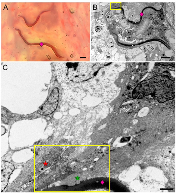
Due to the thickness of the hard plastic embedding medium needed for histological evaluation of metal-containing devices, stain penetration is often inconsistent, resulting in unsuccessful staining of tissues, a common problem seen with the use of some plastic resins (e.g., Technovit 7200). This difficulty is apparent in the current study, evidenced by the lack of blue staining of collagen in the trichrome stained slides (Figure 10A). Thus, TEM was used to ultrastructurally verify the light microscopy findings, specifically the presence of fibrin and collagen. Of note, tissue embedded in plastic was previously fixed in formalin. Formalin fixation may not provide adequate cellular membrane/organelle detail; however, fibrils (i.e., fibrin and collagen) can be readily identified with formalin fixation. Therefore, TEM was performed to verify fibrillary patterns of extracellular matrix rather than cellular detail.
Figure 10.
Trichrome staining of the plastic-embedded vessels was inconsistent across all time points and failed to stain the collagen blue (A). However, transmission electron microscopy (TEM) was used to identify contents of the extracellular matrix. The TEM evaluation (B, C) showed a polymer strut (pink diamond) with adjacent collagen (green asterisk) and fibrin (red asterisk) deposition. The scale bar in (A) and (B) is 5 μm. The scale bar in (C) is 1 μm.
Across all time points, there was the deposition of more mature connective tissue in direct contact with the polymer. The presence of collagen directly adjacent to the polymer (Figure 10B,C) further establishes the overall trend toward healing, as the deposition of mature fibrous connective tissue immediately adjacent to an implanted biomaterial is unlikely to occur if that biomaterial was toxic to the host.
5. CONCLUSION
The histologic assessment of vessels treated with occlusion devices in this study reflects the trend of healing rather than sustained inflammation: overall, the presence of multinucleated giant cells surrounding the IMPEDE polymer, the presumable presence of alternatively activated macrophages, and the deposition of mature collagen are appropriate host responses that indicate these vessels are not exhibiting an acute or chronic, mixed inflammatory reaction but have progressed toward a healing response.
The fluoroscopy contrast study of both the test (IMPEDE) and control (AVP and Nester) devices show similar, overlapping reflow findings at 30, 60, and 90 days postimplantation. However, microscopic evaluation of the implant sites showed that IMPEDE demonstrated a slightly improved degree of healing at all time points compared to AVP and Nester. Moreover, IMPEDE showed improved percent vessel occlusion with no microscopic evidence of intradevice recanalization at any time period. Thus, the coordinated healing (collagenous replacement of retained blood components and polymer platform) from the IMPEDE devices has provided a stable structure to prevent intradevice reflow and/or dissection observed in both control devices. This advantage provides a sustained intravascular occlusion and a sustained ischemic therapeutic effect.
Supplementary Material
ACKNOWLEDGMENTS
The authors would like to acknowledge and express gratitude to Ralph Nichols and Pamela Potts at Texas Heart Institute for their contribution in the transmission electron microscopy of the samples presented in this manuscript. The authors would also like to thank Michael Jorgenson at American Preclinical Services for his assistance during device implantation and follow-up procedures. This work was supported in part by the National Institute of Biomedical Imaging and Bioengineering of the National Institutes of Health under Award number R44EB022016. The content within this publication is solely the responsibility of the authors and does not necessarily represent the official views of the National Institutes of Health.
Footnotes
Supporting Information
The Supporting Information is available free of charge on the ACS Publications website at DOI: 10.1021/acsbiomaterials.9b00895.
Complete data table listing the average percentage of cell types distributed among outer, mid, and inner regions of vessel cross sections implanted with an IMPEDE Embolization Plug, Amplatzer Vascular Plug, and Nester Embolization Coils at 30, 60, and 90 day time points (PDF)
The authors declare the following competing financial interest(s): Shape Memory Medical Inc. (SMM) owns the commercial license for the IMPEDE device described in this work. The authors disclose that Duncan J. Maitland and Fred J. Clubb, Jr. hold stock in SMM. Todd L. Landsman is currently employed by SMM. Further, Duncan J. Maitland is a Director and Chief Technology Officer at SMM.
REFERENCES
- (1).Kessler J; Trerotola SO Use of the Amplatzer Vascular Plug for embolization of a large retroperitoneal shunt during transjugular intrahepatic portosystemic shunt creation for gastric variceal bleeding. J. Vasc Interv Radiol 2006, 17 (1), 135–140. [DOI] [PubMed] [Google Scholar]
- (2).White SB; Stavropoulos SW Management of endoleaks following endovascular aneurysm repair. Semin Intervent Radiol 2009, 26 (1), 33–38. [DOI] [PMC free article] [PubMed] [Google Scholar]
- (3).Laborda A; Medrano J; de Blas I; Urtiaga I; Carnevale FC; de Gregorio MA Endovascular treatement of pelvic congestion syndrome: visual analog scale (VAS) long-term follow-up clinical evaluation in 202 patients. Cardiovasc Intervent Radiol 2013, 36, 1006–1014. [DOI] [PubMed] [Google Scholar]
- (4).Rossi S; Garbagnati F; Lencioni R; Allgaier HP; Marchiano A; Fornari F; Quaretti P; Di Tolla G; Ambrosi C; Mazzaferro V; Blum HE; Bartolozzi C Percutaneous radio-frequency thermal ablation of nonresectable hepatocellular carcinoma after occlusion of tumor blood supply. Radiology 2000, 217, 119–126. [DOI] [PubMed] [Google Scholar]
- (5).Wang W; Li H; Tam MD; Zhou D; Wang DX; Spain J The amplatzer vascular plug: a review of the device and its clinical applications. Cardiovasc Intervent Radiol 2012, 35 (4), 725–740. [DOI] [PubMed] [Google Scholar]
- (6).Bilbao JI; Martinez-Cuesta A; Urtasun F; Cosin O Complications of embolization. Semin Intervent Radiol 2006, 23 (2), 126–142. [DOI] [PMC free article] [PubMed] [Google Scholar]
- (7).Dudeck O; Bulla K; Wieners G; Ruehl R; Ulrich G; Amthauer H; Ricke J; Pech M Embolization of the gastroduodenal artery before selective internal radiotherapy: a prospectively randomized trial comparing standard pushable coils with fibered interlock detachable coils. Cardiovasc Intervent Radiol 2011, 34, 74–80. [DOI] [PubMed] [Google Scholar]
- (8).Enriquez J; Javadi S; Murthy R; Ensor J Jr.; Mahvash A; Abdelsalam ME; Madoff DC; Wallace MJ; Avritscher R Gastroduodenal artery recanalization after transcatheter fibered coil embolization for prevention of hepaticoenteric flow: incidence and predisposing technical factors in 142 patients. Acta Radiol. 2013, 54 (7), 790–794. [DOI] [PubMed] [Google Scholar]
- (9).Trerotola SO; Pyeritz RE Does use of coils in addition to amplatzer vascular plugs prevent recanalization? AJR, Am. J. Roentgenol 2010, 195, 766–771. [DOI] [PubMed] [Google Scholar]
- (10).Landsman TL; Bush RL; Glowczwski A; Horn J; Jessen SL; Ungchusri E; Diguette K; Smith HR; Hasan SM; Nash D; Clubb FJ; Maitland DJ Design and verification of a shape memory polymer peripheral occlusion device. J. Mech Behav Biomed Mater 2016, 63, 195–206. [DOI] [PMC free article] [PubMed] [Google Scholar]
- (11).Rodriguez JN; Yu YJ; Miller MW; Wilson TS; Hartman J; Clubb FJ; Gentry B; Maitland DJ Opacification of shape memory polymer foam designed for treatment of intracranial aneurysms. Ann. Biomed. Eng 2012, 40 (4), 883–897. [DOI] [PMC free article] [PubMed] [Google Scholar]
- (12).Hwang W; Singhal P; Miller MW; Maitland DJ In vitro study of transcatheter delivery of a shape memory polymer foam embolic device for treating cerebral aneurysms. J. Med. Devices 2013, 7 (2), No. 020932. [Google Scholar]
- (13).Ortega JM; Hartman J; Rodriguez JN; Maitland DJ Virtual treatment of basilar aneurysms using shape memory polymer foam. Ann. Biomed. Eng 2013, 41 (4), 725–43. [DOI] [PMC free article] [PubMed] [Google Scholar]
- (14).Rodriguez JN; Miller MW; Boyle A; Horn J; Yang CK; Wilson TS; Ortega JM; Small W; Nash L; Skoog H; Maitland DJ Reticulation of low density shape memory polymer foam with an in vivo demonstration of vascular occlusion. J. Mech Behav Biomed Mater 2014, 40, 102–114. [DOI] [PMC free article] [PubMed] [Google Scholar]
- (15).Horn J; Hwang W; Jessen SL; Keller BK; Miller MW; Tuzun E; Hartman J; Clubb FJ; Maitland DJ Comparison of shape memory polymer foam versus bare metal coil treatments in an in vivo porcine sidewall aneurysm model. J. Biomed. Mater. Res., Part B 2017, 105B, 1892–1905. [DOI] [PMC free article] [PubMed] [Google Scholar]
- (16).Rodriguez JN; Clubb FJ; Wilson TS; Miller MW; Fossum TW; Hartman J; Tuzun E; Singhal P; Maitland DJ In vivo response to an implanted shape memory polyurethane foam in a porcine aneurysm model. J. Biomed. Mater. Res., Part A 2014, 102 (5), 1231–1242. [DOI] [PMC free article] [PubMed] [Google Scholar]
- (17).Herting SM; Ding Y; Boyle AJ; Dai D; Nash LD; Asnafi S; Jakaitis R; Johnson CR; Graul LM; Yeh C; Kallmes DF; Kadirvel R; Maitland DJ In vivo comparison of shape memory polymer foam-coated and bare metal coils for aneurysm occlusion in the rabbit elastase model. J. Biomed. Mater. Res., Part B 2019, DOI: 10.1002/jbm.b.34337. [DOI] [PMC free article] [PubMed] [Google Scholar]
- (18).Boyle AJ; Wierzbicki MA; Herting S; Weems AC; Nathan A; Hwang W; Maitland DJ In vitro performance of a shape memory polymer foam-coated coil embolization device. Medical Engineering & Physics 2017, 49, 56–62. [DOI] [PMC free article] [PubMed] [Google Scholar]
- (19).Weems AC; Wacker KT; Carrow JK; Boyle AJ; Maitland DJ Shape memory polyurethanes with oxidation-induced degradation: in vivo and in vitro correlations for endovascular material applications. Acta Biomater. 2017, 59, 33–44. [DOI] [PMC free article] [PubMed] [Google Scholar]
- (20).Friedrich P; Reininger AJ Occlusive thrombus formation on indwelling catheters: in vitro investigation and computational analysis. Thromb. Haemostasis 1995, 73 (1), 66–72. [PubMed] [Google Scholar]
- (21).Hasan SM; Raymond JE; Wilson TS; Keller BK; Maitland DJ Effects of isophorone diisocyanate on the thermal and mechanical properties of shape-memory polyurethane foams. Macromol. Chem. Phys 2014, 215, 2420–2429. [DOI] [PMC free article] [PubMed] [Google Scholar]
- (22).Friedemann MC; Mehta NA; Jessen SL; Charara FH; Ginn-Hedman AM; Kaulfus CN; Brocklesby BF; Robinson CB; Jokerst S; Glowczwski A; Clubb FJ; Weeks BR Introduction to currently applied device pathology. Toxicol. Pathol 2019, 47 (3), 221–234. [DOI] [PubMed] [Google Scholar]
- (23).Chamberlain CS; Crowley EM; Kobayashi H; Eliceiri KW; Vanderby R Quantification of collagen organization and extracellular matrix factors within the healing ligament. Microsc. Microanal 2011, 17, 779–787. [DOI] [PMC free article] [PubMed] [Google Scholar]
- (24).Yuasa M; Mignemi NA; Barnett JV; Cates JMM; Nyman JS; Okawa A; Yoshii T; Schwartz HS; Stutz CM; Schoenecker JG The temporal and spatial development of vascularity in a healing displaced fracture. Bone 2014, 67, 208–221. [DOI] [PubMed] [Google Scholar]
- (25).Anderson JM; Rodriguez A; Chang DT Foreign body reaction to biomaterials. Semin. Immunol 2008, 20 (2), 86–100. [DOI] [PMC free article] [PubMed] [Google Scholar]
- (26).Sheikh Z; Brooks PJ; Barzilay O; Fine N; Glogauer M Macrophages, foreign body giant cells and their response to implantable materials. Materials 2015, 8 (9), 5671–5701. [DOI] [PMC free article] [PubMed] [Google Scholar]
- (27).Kumar V; Abbas AK; Aster JC Inflammation and repair In Robbins basic pathology, 10th ed.; Elsevier: Philadelphia, PA, 2018; p 57–95. [Google Scholar]
- (28).Das A; Sinha M; Datta S; Abas M; Chaffee S; Sen CK; Roy S Monocyte and macrophage plasticity in tissue repair and regeneration. Am. J. Pathol 2015, 185, 2596–2606. [DOI] [PMC free article] [PubMed] [Google Scholar]
- (29).Anderson JM Biological responses to materials. Annu. Rev. Mater. Res. 2001, 31, 81–110. [Google Scholar]
- (30).Brinjikji W; Kallmes DF; Kadirvel R Mechanisms of healing in coiled intracranial aneurysms: a review of the literature. Am. J. Neuroradiol 2015, 36, 1216–1222. [DOI] [PMC free article] [PubMed] [Google Scholar]
- (31).Uren NG; Melin JA; De Bruyne B; Wijns W; Baudhuin T; Camici PG Relation between myocardial blood flow and the severity of coronary-artery stenosis. N. Engl. J. Med 1994, 330, 1782–1788. [DOI] [PubMed] [Google Scholar]
Associated Data
This section collects any data citations, data availability statements, or supplementary materials included in this article.


