

Abstract
To mimic the bone matrix of mineralized collagen and to impart microporous structure to facilitate cell migration and bone regeneration, we developed a nanofibrous polymer scaffold with highly interconnected pores and three-dimensional calcium phosphate coating utilizing an electrodeposition technique. The mineral content, morphology, crystal structure and chemical composition could be tailored by adjusting the deposition temperature, voltage and duration. A higher voltage and a higher temperature led to a greater rate of mineralization. Furthermore, nearly linear calcium releasing kinetics was achieved from the mineralized 3D scaffolds. The releasing rate was controlled by varying the initial electrodeposition conditions. The higher deposition voltage and temperature led to slower calcium release, which was associated with the highly crystalline and stoichiometric hydroxyapatite content. This pre-mineralized nanofibrous scaffold enhanced bone regeneration over the control scaffold in a subcutaneous implantation model, which was associated with released calcium ions in facilitating osteogenic cell proliferation.
Keywords: calcium phosphate, nanofibrous, three-dimensional, proliferation, bone regeneration
Graphical Abstract

INTRODUCTION
Biomimetic scaffolds that resemble bone extracellular matrix, which consists of collagen nanofibers and nanosized calcium phosphate particles, are advantageous for bone regeneration1–7. Thermally-induced phase separation (TIPS) technique developed in our laboratory has shown advantages in fabricating nanofibrous (NF) matrix with pre-designed three-dimensional (3D) geometry and well-interconnected pores8–10. These features are particularly beneficial in regenerating critical-sized 3D tissue defects11. In addition to creating extracellular matrix (ECM)-like nanofibers, TIPS can be combined with other techniques to build additional porous and architectural features on various size scales. For example, porogen-leaching technique has been combined with TIPS to generate interconnected pores in NF scaffolds to facilitate cell penetration, mass transport of nutrients and metabolic wastes, and the ingrowth of blood vessels, all critical to the regeneration of functional bone12–13. Considerable efforts have been made to incorporate minerals into NF scaffolds to mimic the inorganic phase of bone ECM. While blending mineral particles with polymers prior to nanofiber fabrication is straight-forward, limitations include impaired nanofiber formation, uneven mineral distribution within the polymer phase, and low efficiency of the mineral presentation on scaffold surface14–15. In contrast, surface mineralization of scaffolds circumvents these shortcomings and presents minerals with higher availability to cells16. Although simulated body fluid has been utilized to generate osteoconductive surface on medical implants for about 30 years17–18, the surface mineralization of porous 3D scaffolds remains a challenge. While we previously utilized a simulated body fluid to grow calcium phosphate onto the surface of a 3D porous scaffold12, that was a time-consuming process (taking weeks), which could lead to undesired degradation of the scaffolds prior to their use for bone regeneration. An electrodeposition technique was recently developed to achieve drastically faster mineral deposition on electrospun NF films19, but has not been reported for 3D mineralization of TIPS-generated NF scaffolds. Furthermore, bone is a dynamic tissue that constantly remodels, resulting in extracellular calcium concentration variation, which in turn plays a role in regulating bone cell behavior 20–22. Nonetheless, there has been few publications to develop 3D scaffolds with controllable calcium release capability.
In this study, we successfully applied electrodeposition technique for the 3D mineralization of highly porous NF scaffolds generated by combining TIPS and porogen-leaching techniques. The relationships between the processing parameters (temperature, voltage and duration) and the mineral content, mineral architecture and composition of the resulting scaffolds were examined. Tunable calcium release profiles were achieved by conveniently controlling the parameters of calcium phosphate electrodeposition. Such scaffolds were also experimentally demonstrated to be advantageous over control scaffolds for in vivo bone regeneration, which was found to be associated with enhanced proliferation of osteogenic cells by higher calcium concentrations.
EXPERIMENTAL SECTION
Materials
Poly(L-lactic acid) (PLLA) with an inherent viscosity of 1.4–1.8 dl/g was purchased from Boehringer Ingelheim (Ingelheim, Germany) and was used as received. Mineral oil and sorbitan monooleate (Span 80) were purchased from Sigma (St. Louis, MO). Cyclohexane was purchased from Fisher Scientific (Pittsburgh, PA). Glutaraldehyde and osmium tetroxide were purchased from Electron Microscopy Sciences (Hatfield, PA). Tetrahydrofuran (THF), ammonium phosphate, calcium nitrate and all other chemicals were purchased from Aldrich Chemical Company (Milwaukee, WI).
Fabrication of Macroporous and NF PLLA Scaffolds
Thermally-induced phase separation and porogen leaching techniques were employed to fabricate macroporous NF PLLA scaffolds as previously reported12. Briefly, about 0.6–0.8 mL of 10% PLLA/THF solution was cast into an assembled sugar template (formed from bonded sugar spheres 250–425μm in diameter) under mild vacuum. The PLLA in the PLLA/sugar composite was phase separated at −20°C overnight. Cyclohexane was used to exchange for THF for 2 days. The resulting composites were freeze-dried and immersed in distilled water to leach out the sugar spheres. The scaffolds were freeze-dried again and cut into circular disks with dimensions of 7.2 mm in diameter and 2 mm in thickness. The average weight of the scaffold was 2.5–3.0 mg.
Electrodeposition
The setup for electrodeposition contained two electrodes: a platinum plate electrode (20 × 20 × 0.2 mm) served as the counter electrode and the scaffold-covered electrode as the working electrode. The illustration of the electrodeposition setup has been previously published19. Scaffolds were adhered onto the surface of the stainless-steel electrode using copper foil conductive adhesive. Prior to this, all the scaffolds were immersed into 70% ethanol under vacuum for 15 min in order to reduce the amount of hydrogen gas evolution at the deposition electrode. Mild vacuum was applied during the immersion to wet the large surface area of the highly porous scaffolds. The distance between the two electrodes was fixed at 2.5 cm. The setup was placed in a beaker filled with electrolytes, which was placed in a water bath to maintain the desired temperature. The electrolyte was a solution of 0.042 mol L−1Ca (NO3)2·4H2O and 0.025 mol L−1 NH4H2PO4, with a pH of 4.70. Following deposition, scaffolds were removed from the electrode and heated at 60°C for 30 min to improve adhesion of minerals to the scaffold.
Scaffold Characterization
The morphologies of the scaffolds were examined with scanning electron microscopy (SEM, Philips XL30 FEG) at 8–10 kV as previously reported10, 12. The samples were cut by a razor blade or fractured after liquid nitrogen treatment and coated with gold for 200 s using a sputter coater (Desk II, Denton Vacuum Inc). During the coating, the gas pressure was kept at 50 mtorr and the current was 40 mA.
To determine the total amount of calcium of the mineralized scaffolds, the scaffolds were placed in 1M HCl solution for 2 hrs to fully dissolve the minerals. The supernatant was then collected through centrifugation and analyzed using a commercially available calcium kit (Calcium Liquicolor, Stanbio Laboratory, Boerne, TX, USA). This colorimetric [Ca] assay was performed by following the manufacturer’s protocol, and a standard curve based on a relevant range of [Ca] was generated. Absorbance was measured by a fluorescence microplate reader (Varioskan Flash, Thermo Scientific) at 570 nm. Ion concentrations were calculated based on the standard curve. A blank NF PLLA scaffold (without any minerals) was used as a control.
Calcium Release
In vitro calcium release from mineralized NF PLLA scaffolds was determined as follows. To be consistent with the pretreatment process for seeding cells on scaffolds, the scaffolds were prewet in ethanol under vacuum for 30 min, rinsed in PBS 3 times for 30min each, and in media 1 time for 2 hrs. Each scaffold was then immersed in 1 ml phosphate buffered saline (PBS, 10mM, pH=7.4) and incubated at 37 °C under gentle agitation (60 rpm). At designated time points, samples were centrifuged to collect supernatant for analysis. The same amount of fresh medium was added back to the scaffold for the next time point measurement. The released calcium amount was quantified using a calcium assay kit as detailed above.
Bone Marrow Derived Stromal Cell Isolation and Culture
Bone marrow-derived mesenchymal stromal cells (BMSCs) were obtained from New Zealand white rabbits by aspiration of the femoral and tibial bone marrow using an 18-gauge syringe needle. A total of 10 mL of marrow was collected into 1000 U of heparin-containing maintenance media (high-glucose alpha-MEM (Gibco) containing 10% fetal bovine serum (FBS) (Gibco) and antibiotics (penicillin G, 100 U/mL; streptomycin, 0.1 mg/mL)). The marrow was washed with PBS once and fresh media twice and centrifuged at 2000 rpm for 3 min after each wash. Rabbit BMSCs were collected and cultured in 60-cm2 culture dishes in maintenance media at 37°C under 5% CO2, changing media 3 times per week. Cells were used at passage 3.
Cell Seeding on Scaffolds
Scaffolds were soaked in 70% ethanol for 30 min, washed three times with PBS for 30 min each, and twice in alpha MEM with 10% fetal bovine serum for 30 min each. Nanofibrous scaffolds (5 mm in diameter and 1.5 mm in thickness) with a pore size of 250–420 μm were prepared. Half of the scaffolds were deposited with calcium phosphate (3V and 60°C) for 2 hours (flipped scaffold contact surface with the electrode at 1 hour) with a total calcium phosphate deposition per scaffold (3–3.6 mg) to be approximately 1.2 times the mass of the highly porous scaffold (greater than 95% porosity). Calcium phosphate deposited scaffolds and undeposited scaffolds (control) were seeded with 2.5×10⁵ cells in 13 μL of medium. After 2 hours of initial seeding, sufficient media was added to cover scaffolds, and the cell-seeded scaffolds were further cultured for 22 hours under static condition to enhance cell adhesion on scaffolds.
Subcutaneous Implantation in Mice
Cell-scaffold constructs (n=8) were implanted subcutaneously into nude mice for 4 or 8 weeks. Male 6–8 wk old nude mice (Charles River, Wilmington, MA) were used. Surgery was performed under general anesthesia by inhalation of isoflurane with balanced oxygen. To implant four constructs per mouse, two midsagittal incisions were made on the dorsa, and one subcutaneous pocket was created on each side of each incision. One cell-scaffold construct was implanted into each pocket at random. Eight samples were implanted for each group, and incisions were closed with suture clips. Following a 4 or 8-week implantation period, mice were euthanized with CO2, and implants were harvested. Animal procedures were performed according to a protocol approved by the Institutional Animal Care & Use Committee (IACUC) at the University of Michigan.
MicroCT Analysis of Cell-scaffold Constructs to Assess Ossification
Samples were embedded in 1% agarose and placed in a 14 mm diameter tube and scanned over the entire length of the scaffold using a microCT system (μCT100 Scanco Medical, Bassersdorf, Switzerland). Scan settings were: voxel size 12 μm, 70 kVp, 114 μA, 0.5 mm AL filter, and 500 ms integration time. Analysis was performed using the manufacturer’s evaluation software. A fixed global threshold of 18% (180 on a grayscale of 0–1000) was used to segment bone from non-bone in order to quantify bone volume and create 3D reconstructions. It is important to note that this fixed threshold at 18% is significantly higher than the threshold that the CaP coating is visible (15%), and therefore the initial CaP coating is considered non-bone in this analysis.
Histological Analyses of Cell-scaffold Constructs to Assess Ossification
Constructs were washed in PBS, fixed with 3.7% formaldehyde in PBS overnight, and decalcified in 10% EDTA (pH=7.4) for two weeks. Decalcified constructs were dehydrated via an ethanol gradient, embedded in paraffin, and sectioned at a thickness of 5 μm. For histological analysis, sections were deparaffinized, rehydrated, and stained with hematoxylin and eosin.
In vitro Cell Proliferation Assay
Rabbit BMSCs at passage 3 were plated in a 48 well plate with 9,000 cells per well (n=3 for each culture condition). Cells were cultured in 4 different growth media conditions with 1) calcium-free DMEM containing 2 mM glutamine, or alpha MEM with 2) 70 μg/mL calcium (base), 3) 140 μg/mL calcium or 4) 280 μg/mL calcium. To reach 140 μg/mL and 280 μg/mL calcium concentrations, sterile 1M calcium chloride was added to the base alpha MEM formulation which contained 70 μg/mL calcium. The following supplements were also added to all media conditions: 10% FBS, 100 U/mL penicillin, and 100 μg/mL streptomycin. To induce osteogenic differentiation media was supplemented to contain: 100 nM dexamethasone, 10 mM β-glycerophosphate, and 50 μg/mL ascorbic acid. Media was changed three times per week.
Cell number was determined using CCK-8 cell counting kit (Dojingo, Japan) according to the manual. Briefly, at each time point, 15 μl of CCK-8 reagent plus 150 μl of fresh medium was added to each well and incubated at 37°C for 1 hour to induce color change. At predetermined time points, forty μl of reagent/medium from each well was transferred to a 96 well plate in triplicate, and absorbance was read at 450nm using Varioskan Flash Microplate Reader (Thermo Scientific). The culture plate was washed with PBS twice, fresh medium was added, and culture was continued to determine the cell numbers for the next time points, until the end of the 14-day study.
Quantitative Real-time PCR Gene Expression Assay
Rabbit BMSCs at passage 3 were plated in a 24 well plate with 45,000 cells per well (n=3 wells per analysis). Cells were cultured in the same osteogenic differentiation media described in the proliferation study for 14 days with varied calcium concentration (0, 70, 140, and 280 μg/mL). Media was changed three times per week. RNA was extracted using Trizol according to the manufacturer’s instructions by adding 1 mL to each plate well. Reverse transcription-PCR was then performed to form cDNA using Superscript II RT kit according to the manual. Quantitative real-time PCR was performed using TaqMan Universal PCR Master Mix and pre-designed primers for osteopontin and bone sialoprotein, with a ViiA 7 Real time PCR system. Gene expression levels were normalized against GAPDH expression.
Statistical analysis
To test the significance of observed differences between the study groups, the Student’s t-test was applied. A value of p<0.05 was considered to be statistically significant. Analysis of bone volume results were performed using ANOVA followed by a post-hoc Tukey test in JMP Pro 11 software (SAS).
RESULTS AND DISCUSSION
3D Mineralization
3D NF PLLA scaffolds with pore diameters ranging from 250 to 425 μm were fabricated for electrodeposition of calcium phosphate minerals. Prior to electrodeposition, the scaffolds were immersed in ethanol and subjected to mild vacuum to remove trapped air and to wet the NF surface of the scaffold. This treatment also minimized hydrogen gas evolution at the deposition electrode, critical to the 3D mineralization of the porous scaffolds. Minerals with flower-like morphologies were first successfully deposited on both the outer (Figure 1a&b) and inner pores (Figure 1c&d) of the scaffolds after 30 min of electrodeposition at 3V and 60°C, demonstrating the feasibility of 3D mineralization of porous scaffolds. The size of individual flowers is in the order of 10 μm across. The difference between the sizes of the CaP flowers in an inner pore or the outer surface is not statistically significant (Supporting Information, Section A, Figure S1). Through adjusting the electrodeposition parameters, including temperature, voltage and duration, the structure, composition and amount of the deposited minerals were systematically studied in the following sections.
Figure 1.

SEM micrographs of mineralized 3D NF PLLA scaffolds after electrodeposition at 60°C and 3V for 30 min. (a) external structure, (b) amplified image of (a), (c) internal structure, and (d) amplified image of (c).
Control of Mineral Content
How the processing parameters affect the amount of mineral deposition onto the 3D scaffolds was examined. First, the electrodeposition voltage was varied (2, 3, 5 and 6 V) at a fixed temperature (60°C) and the mass increases of the scaffolds during electrodeposition were measured over time. It was found that the voltage played an important role in the amount of minerals being deposited on to the scaffolds. The amount of minerals increased with increasing deposition voltage and increasing deposition time (Figure 2a). Electrodeposition at 6V, for example, resulted in more than 80% mass increase, more than twice the amount of the deposited minerals at 2V at the same temperature and over the same time duration (Figure 2a).
Figure 2.

(a) Mass increase of 3D NF PLLA scaffolds electrodeposited for calcium phosphate for 15, 30 and 60 min under an electrical voltage of 2V, 3V, 5V and 6V at a temperature of 60°C (n=3). (b) Mass increase of 3D NF PLLA scaffolds electrodeposited for calcium phosphate for 15, 30 and 60 min under a voltage of 3V and at a temperature of 25°C, 40°C, 50°C and 60°C, respectively (n=3).
When the voltage was kept at 3V, electrodeposition was carried out at varied temperatures (25, 40, 50, 60 °C) and the mass increases of the scaffolds were measured over electrodeposition time. The mineral content increased substantially with increasing deposition time (Figure 2b). Interestingly, the increase in temperature only slightly increased the amount of deposited minerals in the temperature range studied. Importantly, it was found that under fixed electrodeposition conditions, the mass increased with deposition time nearly linearly, indicating a constant mineral deposition rate. Therefore, a linear regression model was employed to calculate the deposition rate (the slope of the regression line) under each electrodeposition condition. Hence, the electrodeposition parameters (voltage, temperature and duration) can be programmed to achieve a targeted amount of 3D mineral coating onto the porous NF scaffolds.
Mineral Morphologies
An important advantage of the electrodeposition technique is the facile control of the structure and composition of the mineralization through adjusting the electrodeposition parameters. First, the electrodeposition voltage was found to have a major effect on the chemical composition and physical structure of the deposited minerals. The morphology of mineral coating changed significantly with varying deposition voltages at a fixed temperature of 60 °C (Figure 3a–d). It should be noted that the mineral amounts were purposely controlled the same among these four groups (50% mass increase). A lower deposition voltage (such as 2V) resulted in minerals with a flower-like topography (Figure 3a). A slight increase in deposition voltage (3V) transformed the flower-like morphology into flake-like morphology (smaller mineral plate aggregates) (Figure 3b). When higher voltages (5 and 6V) were applied, a small fiber-like coating was generated (Figure 3c&d). The mineral structures were consistent throughout the scaffolds.
Figure 3.
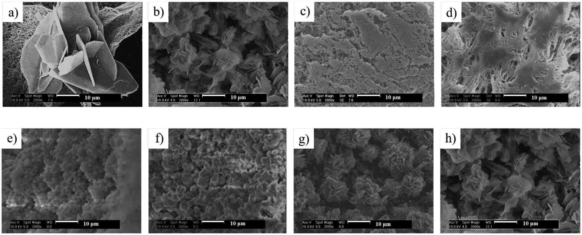
SEM micrographs of 3D NF PLLA scaffolds electrodeposited for calcium phosphate: (a-d) under a voltage of 2V (a), 3V (b), 5V (c) and 6V (d) at a temperature of 60°C; (e-h) under a voltage of 3V at a temperature of 25°C (e), 40°C (f), 50°C (g) and 60°C (h), respectively. The mass increase of all scaffolds was set at 50%.
Second, when the deposition voltage was fixed (at 3V), the deposition temperature was also found to affect the structure of the mineral coatings. Based on SEM observation, the coating obtained at 25°C and 40°C consisted of minerals with a particle structure (Figure 3e&f). When the deposition temperature was increased to 50 and 60°C, flake-like minerals were formed (Figure 3g&h). The changes in mineral particle size were quantified (Supporting Information, Section A, Figure S2).
The minerals with different morphologies had different mineral structures and chemical compositions. We employed X-ray diffraction (XRD) to investigate the mineral structure and composition of the minerals under each deposition condition. From the XRD patterns (Figure 4a&b), the deposited minerals transitioned from dicalcium phosphate dihydrate (DCPD) to hydroxyl apatite (HA) when the applied voltage increased from 2V to 6V (temperature at 60 °C). At a lower deposition voltage of 2V, the XRD pattern clearly showed the DCPD peak (020) at 2θ = 11.7°, which was in the JCPDS card (Joint Committee on Powder Diffraction Standards, card number 09–0077), suggesting that the minerals were mostly DCPD. When the voltage increased to 3V, diffraction peaks corresponding to HA phase started to appear (JCPDS card number 09–0432), while the major phase was still DCPD. When the deposition voltage was further increased, the structure of the minerals followed this transitioning trend, evidenced by the further increase of HA content and decrease of DCPD content at the voltage of 5V and 6V. This trend was quantified by calculating the HA to DCPD ratio (measured by XRD), which increased as the voltage increased (Figure 4c). For a deposition voltage of 2V, the HA/DCPD ratio was 0.03:1, which increased to 3.71:1 when the deposition voltage increased to 6V. Similarly, the XRD patterns of the mineralized scaffolds showed the mineral transformation from DCPD to HA when the deposition temperature increased from 25 °C to 60 °C (Figure 4d&e). This trend was also quantified by the HA/DCPD ratio calculation using XRD data (Figure 4f). HA/DCPD ratio increased from 0.03:1 to 1.78:1 when the deposition temperature increased from 25 °C to 60°C. EDS analysis showed consistent change of Ca/P ratio in response to electrodeposition temperature or voltage change (Supporting Information, Section B, Figure S3). It is known that DCPD is a nucleation precursor that can transform into the more thermodynamically stable HA at a higher electrodeposition voltage or temperature19.
Figure 4.

(a, b) XRD patterns of scaffolds deposited under a voltage of 2V, 3V, 5V and 6V (n=3) at a temperature of 60°C (α-DCPD, β-PLLA, γ-HA); (c) the HA to DCPD ratio of mineralized scaffolds deposited under different voltages (n=3). (d, e) XRD patterns of scaffolds deposited under a voltage of 3V at a temperature of 25°C, 40°C, 50°C and 60°C (n=3) (α-DCPD, β-PLLA, γ-HA); (f) the HA to DCPD ratio of mineralized scaffolds deposited at different temperatures (n=3). The total mass increase of all scaffolds was set to 50%.
Advantageously, the increase in voltage or temperature during electrodeposition could facilitate this transformation under a mild processing condition, while other potential methods, including hydrothermal treatment19, 23–24, sintering25, and alkaline treatment26–27, typically involve harsh processing conditions (such as high temperature and an alkaline environment) that may lead to polymer degradation.
Calcium Content
The amount of calcium in a mineralized scaffold and its releasing profile are important for bone tissue engineering. To determine the total amount of calcium in the deposited minerals, the scaffolds were immersed in HCl solution for 2 hrs so that all minerals were dissolved. Using a commercial calcium quantification kit, we investigated how each electrodeposition parameter (voltage, temperature and duration) affected the total calcium content in the minerals. At varying deposition voltages (the temperature was fixed at 60 °C), the calcium deposition increased essentially linearly with deposition time (Supporting Information, Section C, Figure S4a). In other words, the rate of calcium deposition was a constant at each deposition voltage. The rate of calcium deposition increased with increasing deposition voltage (Supporting Information, Section C, Figure S4a, Table S1). For example, the calcium amount of the mineralized scaffold deposited at 2V for 60 min was about 12.42%, which increased to 16.7% at 3V, 23.7% at 5V and 28% at 6V, respectively. This trend correlates with our earlier data that increasing voltage lead to the increase of both total mineral content and HA/DCPD ratio (HA has a higher calcium content than DCPD) (Figure 2a, 4c). Similarly, at a fixed voltage of 3V under varying deposition temperatures, the total calcium content increased linearly with increasing time, also showing a constant rate of calcium deposition (Supporting Information, Section C, Figure S4b). The rate of calcium deposition increased slightly when the deposition temperature increased (Supporting Information, Section C, Figure S4b, Table S2), in good agreement with earlier data of total mineral contents (Figure 2b, 4f). Deposition at 3V for 60min generated a total amount of calcium of 13.73% at 25 °C, which increased to 14.56% at 40°C, 15.62% at 50°C and 16.70% at 60°C, respectively. The corresponding calcium deposition rates under different voltage or temperature were obtained using linear regression (Supporting Information, Section C, Figure S4c&d), the slopes of the regression lines at each electrodeposition condition. Therefore, the electrodeposition conditions (voltage, temperature and duration) can be programmed to achieve a 3D mineral coating consisting of a targeted amount of calcium.
Calcium Release Rate
We hypothesized that the scaffolds mineralized under different conditions might have different calcium releasing profiles due to the different mineral structures and compositions. In order to compare the calcium releasing profiles at different deposition conditions, we prepared mineralized scaffolds at different voltages and temperatures to have the same amount of minerals (50% total mass increase) utilizing the linear regression data obtained in this study (Figure 2).
First, we compared the calcium release profile of mineralized scaffolds prepared at the same temperature (60 °C) and different deposition voltages (Figure 5a). Sustained release of calcium over 3 weeks was achieved, and minerals deposited at a lower voltage had a faster calcium releasing rate. Although our findings showed that a lower voltage led to a lower Ca/P ratio (a lower HA/DCPD ratio) (Figure 4c) and a lower amount of total calcium (Supporting Information, Section C, Figure S4), the physical structure (crystallinity) of the minerals seemed to play a more important role in calcium release rate. We recorded the morphological changes of the minerals over time (0, 7 and 14 days) as shown in Figure 6. Mineralized scaffolds deposited at 2V had a flower-like mineral structure (Figure 6a), which should have a lower specific surface area compared to the smaller flake-like structure (deposited at 3V) or thin fibrous structure (deposited at 5 or 6 V). However, the minerals generated at 2V dissolved at a faster rate, which is likely due to their more amorphous structure (based on their lower HA/DCPD ratio). After 14 days, a significant amount of minerals disappeared (Figure 6c), consistent with the faster calcium release rate. For mineralized scaffolds prepared at 3V, the flake-like minerals had a higher HA/DCPD ratio (higher crystallinity), leading to a slower mineral dissolution rate and a slower calcium release rate. A certain amount of minerals remained after 7 and 14 days (Figure 6e&f). For mineralized scaffolds deposited at 5V and 6V, the minerals had an even higher HA/DCPD ratios (higher overall crystallinity), which led to the slowest mineral dissolution rates and slowest calcium release rates. These results indicate that the crystallinity (HA/DCPD ratio) dominates over the mineral surface area effect in terms of mineral dissolution rate and calcium release rate.
Figure 5.

Calcium release profiles of 3D NF PLLA scaffolds electrodeposited with calcium phosphate: (a) deposited at a voltage of 2V, 3V, 5V and 6V and a temperature of 60°C; (b) deposited at a voltage of 3V and a temperature of 25 °C, 40 °C, 50 °C and 60 °C. The deposited calcium phosphate mass was set to be 50% of that of the scaffold for all samples (n=3).
Figure 6.

SEM micrographs of pre-mineralized NF PLLA scaffolds after being incubated in phosphate buffered saline at 37 °C for 0 days (a, d, g and j), 7 days (b, e, h and k) and 14 days (c, f, i and l). Scaffolds were electrodeposited for calcium phosphate under the voltages of 2V (a-c), 3V (d-f), 5V (g-i) and 6V (j-l) at a temperature of 60°C. The mass increase of all samples was set to 50% during pre-mineralization.
Second, we compared the calcium release profile of mineralized scaffolds prepared at different deposition temperatures (Figure 5b). The deposition voltage was set at 3V and the mass increase of the scaffolds was fixed at 50%. Similarly, all scaffolds prepared at different temperatures had a sustained calcium release up to 3 weeks (Figure 5b). Consistently, a higher deposition temperature also led to a higher crystallinity, higher Ca/P ratio (higher HA/DCPD ratio), and therefore a slower calcium release rate (Figure 5b). The trend of mineral dissolution of these mineralized NF scaffolds at different deposition temperatures was also consistently visualized under SEM observation (Supporting Information, Section D, Figure S5).
Calcium Phosphate/PLLA Composite Scaffolds Enhance Bone Regeneration in vivo
Our composite scaffolds aim to combine the biologically advantageous properties of ECM-mimicking nanofibers and osteoconductive CaP minerals. We hypothesized that CaP electrodeposited NF PLLA scaffolds are more suitable matrices for mineralized tissue regeneration, compared to uncoated NF PLLA scaffolds. Scaffolds both with and without a calcium phosphate (CaP) surface coating were seeded with rabbit BMSCs and implanted subcutaneously into nude mice for up to 8 weeks. The majority of the host cells at the implantation site are not bone-forming cells (largely fibroblasts). Their invasion into a scaffold leads to some fibrous tissue formation but not bone formation unless strong osteogenic growth factors such as bone morphogenetic proteins (BMPs) are used as we previously published28. Three-dimensional micro computed tomographic (μCT) reconstruction of explants demonstrated that the CaP coating facilitated mineralized tissue formation, apparent at 4 weeks post-implantation (Figure 7A, the top view). The untreated PLLA scaffold showed minimal ectopic bone formation after 4 weeks, concentrated to the periphery but not uniform throughout. In contrast, the CaP coated explant was characterized by robust and uniform bone formation throughout the entire scaffold. After 8 weeks, this difference was consistent, supporting the conclusion that CaP electrodeposition facilitates ectopic bone formation in vivo. CaP-deposited NF PLLA scaffolds significantly increased new bone formation, as compared to untreated NF PLLA scaffolds at both time points (Figure 7B, p≤0.01).
Figure 7:

Micro computed tomography (μCT) was used to assess differences in mineralized neotissue between cell-laden CaP/PLLA and cell-laden PLLA constructs by spatial distribution within the construct (A) and volume (B) after 4 and 8 weeks of subcutaneous implantation. *p<0.05, **p<0.01, ***p<0.001, ****p<0.0001, n=8.
Histologic analysis indicated that CaP-deposited scaffolds showed increased bone formation throughout (Figure 8), both in abundance and thickness, compared to an untreated NF PLLA scaffold after 4 weeks of subcutaneous implantation. In addition to increased mineralized tissue, CaP-deposited scaffolds showed an increased cellularity, abundant immune cells and increased adipocyte density, characteristic of bone marrow-like tissue. The same trends were observed after 8 weeks of subcutaneous implantation (Figure 8). CaP coated scaffold facilitate characteristic mature bone formation at 8 weeks, indicated by darkly-stained immune cells, adipocytes, and large blood vessels containing red blood cells (arrow).
Figure 8:

Representative images of H&E stained sections after 4 (A-D) and 8 (A’-D’) weeks subcutaneous implantation. 40x magnification = 500 um scale; 100x magnification = 250 um scale. Arrow indicates blood vessel with red blood cells. n=8.
Effect of Calcium Concentration on Osteogenic Cell Proliferation and Differentiation
Calcium (Ca2+) plays a critical role in regulating osteoblastic and osteoclastic functions in the bone microenvironment29–30. We hypothesized that the concentration of calcium released from a polymer/CaP composite scaffold could regulate the proliferation and differentiation of osteogenic cells and subsequently bone regeneration. Given that CaP-deposited NF PLLA scaffolds demonstrated enhanced osteogenesis as compared to untreated scaffolds in vivo, we investigated the role of calcium ions (Ca2+) in cell proliferation and differentiation in vitro. Rabbit BMSCs were cultured in osteogenic media containing varying amounts of dissolved Ca2+ from calcium chloride (CaCl2). Throughout the 14-day experiment, CCK-8 proliferation assay results demonstrated that exogenous Ca2+ plaid a significant role in facilitating BMSC proliferation in vitro, when combined with osteogenic media (Figure 9A). In the absence of Ca2+, cells proliferated minimally, and did reached a plateau during the 14 days. All other Ca2+ containing differentiation medium cultures reached a plateau by day 7, including the standard osteogenic differentiation medium (70 μg/mL Ca2+). This result likely indicates that differentiation started to dominate over proliferation in the competition. Maximum proliferation was attained at the Ca2+ concentration of 280 μg/mL. It appears to be a clear trend that increasing Ca2+ concentration in osteogenic media positively influences BMSC proliferation. Interestingly, in a growth medium also containing varying amounts of Ca2+, BMSCs proliferated more similarly and were less dependent on Ca2+ concentration (Figure 9A), possibly indicated that there was minimal differentiation to compete with proliferation when cultured in a growth medium. Similar phenomenon was observed with a preosteoblastic cell line (MC3T3-E1) culture in terms of proliferation in response to calcium concentration (Supporting Information, Section E, Figure S6).
Figure 9: Calcium effects on rBMSC proliferation and differentiation.
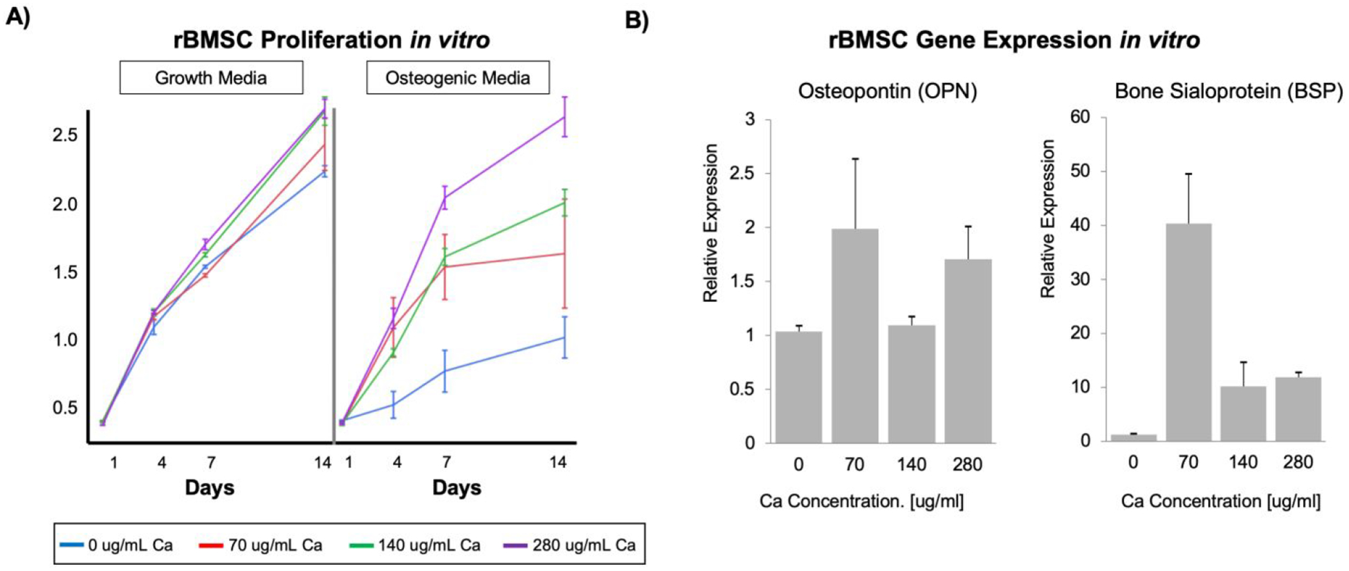
A) Proliferation of rBMSCs cultured in growth and osteogenic differentiation media containing dissolved calcium, for 14 days (A, n=3). B) Relative osteopontin (OPN) and bone sialoprotein (BSP) gene expression, indicating mature differentiation of rBMSCs cultured in osteogenic media supplemented with 70 μg/mL Ca2+ for 14 days.
Quantitative polymerase chain reaction (qPCR) analysis was performed after 14 days of rabbit BMSC culture in vitro for two key osteogenic differentiation markers: osteopontin (OPN), a middle-phase differentiation marker, and bone sialoprotein (BSP), a later-phase marker of osteogenic differentiation. The difference in OPN expression was not statistically significant between different calcium concentrations by day 14 (Figure 9). Interestingly, BSP expression was 4-fold higher in 70 μg/mL Ca2+ media as compared to 140 and 280 μg/mL Ca2+ media (Figure 9). We postulated that 70 μg/mL Ca2+-cultured cells reached late-stage osteogenic differentiation more quickly than at higher Ca2+ concentrations, resulting in the observed plateau. The BSP gene expression data appears to support that BMSCs cultured in 70 μg/mL Ca2+ medium reached a more mature gene expression profile more quickly than BMSCs cultured in 140 and 280 μg/mL Ca2+ media. Thus, the increased Ca2+ content delays maturation of cells and allows greater proliferation before reaching maturation, leading to increased bone volume, while reaching the same terminal fate. This in vitro data suggests that the electrodeposited CaP coating imparts its osteogenic properties by slowly dissolving in the extracellular fluids, releasing Ca2+ locally. We attribute the functional differences between electrodeposited and un-treated NF PLLA scaffolds to a sustained Ca2+ enriched microenvironment, which facilitates BMSC proliferation and therefore bone formation.
Bone matrix, a natural composite material of nanosized collagen fibers and nanosized calcium phosphate minerals, serves both the structural function with remarkable mechanical properties and the biological function as a dynamic source of calcium and phosphate ions to maintain homeostasis in the body31, including in bone formation, resorption, and remodeling. Calcium phosphate is known to be biologically active in mediating osteoconductivity and in certain sense osteoinductivity32–34, and is therefore an important category of biomaterials for bone implants and bone regeneration35. While there have been numerous studies on coating medical devices17–18, polymer films36 or scaffolds12, 16, 37 with calcium phosphate to enhance biocompatibility or osteoconductivity, there has been few to control the calcium release from such coatings, especially from a 3D tissue engineering scaffold. Therefore, it is of fundamental importance to understand the physiology and develop ways to control calcium and phosphate concentrations. We desire to coat calcium phosphate on NF polymer scaffolds and to understand their release behavior from such composite materials. In this work, we successfully employed electrodeposition technique to achieve rapid 3D mineralization of porous NF PLLA scaffolds without compromising the porous network of the 3D scaffolds for bone regeneration. Advantageously, the morphologies and chemical compositions of the minerals can be conveniently controlled by adjusting electrodeposition parameters including voltage, temperature and duration. Through a linear regression model, we were able to program electrodeposition parameters and deposit a targeted amount of minerals onto such 3D NF scaffolds. Importantly, through manipulating the morphology, structure and chemical composition of the minerals, the calcium release profile of the 3D mineralized scaffolds can be controlled. Such technology can be utilized to tailor the calcium phosphate content, crystallinity (HA/DCPD ratio), and thereby to control their release and regulate the proliferation and differentiation of osteogenic stem or progenitor cells for bone regeneration.
Calcium and phosphate ions are the source materials for mineralized bone formation35, 38. Additionally, it has been reported that calcium ions increase the life span of osteoblasts39, stimulate osteoblastic differentiation and bone synthesis40, and also regulate osteoclastogenesis41. Phosphate ions regulate osteoblast differentiation, the expression of bone morphogenetic proteins42–43, and also regulate RANKL:OPG ratio to inhibit osteoclast differentiation and bone resorption44–45. While this study was mainly focused on the electrodeposition technology and the release kinetics of calcium ions, the released phosphate ions from the calcium phosphate on the nanofibrous scaffolds likely also played a role in bone regeneration. In addition to mineralized tissue regeneration, the calcium phosphate eletrodeposition technology may also be utilized to investigate and regulate calcium and phosphorous homeostasis in many other tissues such as in nerve transmission and conduction, muscle contraction, and cardiac beating in the future.
Moreover, both the nearly linear deposition rate of calcium phosphate on to these highly porous and NF PLLA scaffolds and the essentially linear calcium release rate from the resulting partially mineralized NF scaffolds are novel findings. The facts that their mass increases or decreases nearly linearly with time, indicate that diffusion is not the rate determining step in their calcium deposition or release processes. Otherwise, their calcium deposition would be proportional to the square root of time as typically reported for calcium phosphate coating on solid metallic implants46. Such deviations could be in part due to the highly porous structure and the high surface area of the NF PLLA scaffolds, could also be in part due to the different calcium phosphate formation reactions occurring on a metallic surface (electron transfer) and in the pores of a polymer scaffold (calcium and phosphate ions to react and form insoluble calcium phosphate, depositing on the pore surface). In any case, the linear deposition and release rates of calcium are fortunately convenient for the intended sustained calcium release in regulating bone regeneration.
The in vivo data confirmed our hypothesis that electrodeposited CaP in a nanofibrous scaffold indeed facilitated bone regeneration. The in vitro studies suggest that the calcium release from the CaP likely facilitates the proliferation of osteogenic cells. However, there seems to be an optimal calcium concentration for the osteogenic differentiation (70μg/ml), above which the enhanced bone regeneration may likely result from the calcium enhanced BMSC proliferation, leading to larger bone volume regeneration.
CONCLUSIONS
Highly porous 3D NF PLLA/calcium phosphate composite scaffolds with tunable calcium phosphate deposition rate, morphology, crystallinity and their calcium release rate have been developed in this work using an electrodeposition method. The electrodeposition rate of the calcium phosphate can be accelerated by increasing either the voltage or the temperature of the deposition. The mass of the calcium phosphate increases nearly linearly with the electrodeposition time at a fixed temperature and a preset voltage. The HA/DCPD ratio (crystallinity and calcium content) of the calcium phosphate deposited on the 3D scaffolds increases with increased deposition voltage and temperature. The calcium release rate from the 3D NF PLLA/calcium phosphate composite scaffolds decreases with increasing voltage and increasing temperature of the pre-mineralization process, which is likely due to the increased crystallinity of the deposited calcium phosphate (increased HA/DCPD ratio) under such electrodeposition conditions, leading to lower solubility in aqueous solution. In an ectopic implantation model, electrodeposited calcium phosphate (CaP) on a NF PLLA scaffold enhanced bone regeneration with rabbit BMSCs compared to the control NF PLLA scaffold. Furthermore, we showed that calcium promoted the proliferation of osteogenic cells (BMSCs or preosteoblasts) for bone regeneration. These understandings open an avenue to precisely control calcium phosphate morphology, crystallinity/composition, and the release rates of calcium from a 3D scaffold for bone regeneration or other biomedical applications.
Supplementary Material
ACKNOWLEDGEMENTS
This work was carried out in the Polymeric Biomaterials and Tissue Engineering Laboratory at the University of Michigan. XM and MJG contributed overall equally to this work. XM, ZZ and MJG drafted the initial two manuscripts. XM carried out the biomaterials studies, including polymer scaffold fabrication, calcium phosphate electrodeposition, structural characterizations and quantifications, calcium release kinetics and mineral morphology changes. MJG carried out cell culture, molecular characterizations, subcutaneous implantation, μCT and histological analyses. ZZ participated significantly in the biomaterials studies with XM. WBS reformatted the biological figures from MJG manuscript. PXM organized and supervised the entire project, trained study participants, obtained funding, analyzed and interpreted data with trainees, combined the data from XM and MJG, revised and finalized the manuscript, and is the corresponding author. LKM participated in the discussion, data interpretation of biological results, obtaining funding, and manuscript revision. The authors would like to acknowledge the financial support from the NIH (DE027662, DE022327, DE015384) and the technical assistance of Amy Koh for osteoblast cultures. XM’s living in Ann Arbor was partially supported by a scholarship from China Scholarship Council.
Footnotes
Supporting Information
Supporting Information is available at the website of ACS Applied Materials & Interfaces: A) Mineral particle size and size distribution measurements, how the size change with electrodeposition conditions (temperature, voltage, and time); B) Quantification of Ca/P ratio using energy-dispersive spectroscopy (EDS), how the Ca/P ratio change with electrodeposition conditions; C) Data on calcium deposition rate as a function of deposition conditions; D) Morphological changes of pre-mineralized nanofibrous scaffolds during calcium phosphate dissolution; E) Effect of calcium concentration on pre-osteoblast proliferation.
REFERENCES
- 1.Zhang Z; Hu J; Ma PX, Nanofiber-based Delivery of Bioactive Agents and Stem Cells to Bone Sites. Advanced Drug Delivery Reviews 2012, 64 (12), 1129–1141. [DOI] [PMC free article] [PubMed] [Google Scholar]
- 2.Liao S; Nguyen LTH; Ngiam M; Wang C; Cheng Z; Chan CK; Ramakrishna S, Biomimetic Nanocomposites to Control Osteogenic Differentiation of Human Mesenchymal Stem Cells. Advanced Healthcare Materials 2014, 3 (5), 737–751. [DOI] [PubMed] [Google Scholar]
- 3.Gao X; Song J; Ji P; Zhang X; Li X; Xu X; Wang M; Zhang S; Deng Y; Deng F; Wei S, Polydopamine-Templated Hydroxyapatite Reinforced Polycaprolactone Composite Nanofibers with Enhanced Cytocompatibility and Osteogenesis for Bone Tissue Engineering. ACS Appl Mater Interfaces 2016, 8 (5), 3499–515. [DOI] [PubMed] [Google Scholar]
- 4.Li J; Baker BA; Mou X; Ren N; Qiu J; Boughton RI; Liu H, Biopolymer/Calcium Phosphate Scaffolds for Bone Tissue Engineering. Advanced Healthcare Materials 2014, 3 (4), 469–484. [DOI] [PubMed] [Google Scholar]
- 5.Ma PX, Biomimetic Materials for Tissue Engineering. Advanced Drug Delivery Reviews 2008, 60 (2), 184–198. [DOI] [PMC free article] [PubMed] [Google Scholar]
- 6.Kawecki F; Clafshenkel WP; Fortin M; Auger FA; Fradette J, Biomimetic Tissue-Engineered Bone Substitutes for Maxillofacial and Craniofacial Repair: The Potential of Cell Sheet Technologies. Adv Healthc Mater 2018, 7 (6), e1700919. [DOI] [PubMed] [Google Scholar]
- 7.Pina S; Oliveira JM; Reis RL, Natural-based Nanocomposites for Bone Tissue Engineering and Regenerative Medicine: a Review. Advanced Materials 2015, 27 (7), 1143–69. [DOI] [PubMed] [Google Scholar]
- 8.Ma PX; Zhang R, Synthetic Nano-scale Fibrous Extracellular Matrix. Journal of Biomedical Materials Research 1999, 46 (1), 60–72. [DOI] [PubMed] [Google Scholar]
- 9.Liu X; Ma PX, Phase Separation, Pore Structure, and Properties of Nanofibrous Gelatin Scaffolds. Biomaterials 2009, 30 (25), 4094–4103. [DOI] [PMC free article] [PubMed] [Google Scholar]
- 10.Liu X; Ma PX, The Nanofibrous Architecture of Poly(l-lactic acid)-based Functional Copolymers. Biomaterials 2010, 31 (2), 259–269. [DOI] [PMC free article] [PubMed] [Google Scholar]
- 11.Chen VJ; Smith LA; Ma PX, Bone Regeneration on Computer-designed Nano-fibrous Scaffolds. Biomaterials 2006, 27 (21), 3973–3979. [DOI] [PubMed] [Google Scholar]
- 12.Wei G; Ma PX, Macroporous and Nanofibrous Polymer Scaffolds and Polymer/bone-like Apatite Composite Scaffolds Generated by Sugar Spheres. Journal of Biomedical Materials Research Part A 2006, 78A (2), 306–315. [DOI] [PubMed] [Google Scholar]
- 13.Gupte MJ; Swanson WB; Hu J; Jin X; Ma H; Zhang Z; Liu Z; Feng K; Feng G; Xiao G; Hatch N; Mishina Y; Ma PX, Pore Size Directs Bone Marrow Stromal Cell Fate and Tissue Regeneration in Nanofibrous Macroporous Scaffolds by Mediating Vascularization. Acta Biomater 2018, 82, 1–11. [DOI] [PMC free article] [PubMed] [Google Scholar]
- 14.Zhang R; Ma PX, Poly(alpha-hydroxyl acids)/hydroxyapatite Porous Composites for Bone Tissue Engineering. I. Preparation and Morphology. Journal of Biomedical Materials Research 1999, 44 (4), 446–55. [DOI] [PubMed] [Google Scholar]
- 15.Wei G; Ma PX, Structure and Properties of Nano-hydroxyapatite/polymer Composite Scaffolds for Bone Tissue Engineering. Biomaterials 2004, 25 (19), 4749–57. [DOI] [PubMed] [Google Scholar]
- 16.Zhang R; Ma PX, Porous Poly(L-lactic acid)/apatite Composites Created by Biomimetic Process. Journal of Biomedical Materials Research 1999, 45 (4), 285–93. [DOI] [PubMed] [Google Scholar]
- 17.Kokubo T; Kushitani H; Sakka S; Kitsugi T; Yamamuro T, Solutions Able to Reproduce in vivo Surface-structure Changes in Bioactive Glass-ceramic A-W. Journal of Biomedical Materials Research 1990, 24 (6), 721–34. [DOI] [PubMed] [Google Scholar]
- 18.Xie CM; Lu X; Wang KF; Meng FZ; Jiang O; Zhang HP; Zhi W; Fang LM, Silver Nanoparticles and Growth Factors Incorporated Hydroxyapatite Coatings on Metallic Implant Surfaces for Enhancement of Osteoinductivity and Antibacterial Properties. ACS Applied Materials & Interfaces 2014, 6 (11), 8580–9. [DOI] [PubMed] [Google Scholar]
- 19.He C; Xiao G; Jin X; Sun C; Ma PX, Electrodeposition on Nanofibrous Polymer Scaffolds: Rapid Mineralization, Tunable Calcium Phosphate Composition and Topography. Advanced Functional Materials 2010, 20 (20), 3568–3576. [DOI] [PMC free article] [PubMed] [Google Scholar]
- 20.Zayzafoon M, Calcium/calmodulin Signaling Controls Osteoblast Growth and Differentiation. Journal of Cellular Biochemistry 2006, 97 (1), 56–70. [DOI] [PubMed] [Google Scholar]
- 21.Ma S; Yang Y; Carnes DL; Kim K; Park S; Oh SH; Ong JL, Effects of Dissolved Calcium and Phosphorous on Osteoblast Responses. Journal of Oral Implantology 2005, 31 (2), 61–67. [DOI] [PubMed] [Google Scholar]
- 22.Jung G-Y; Park Y-J; Han J-S, Effects of HA Released Calcium Ion on Osteoblast Differentiation. Journal of Materials Science: Materials in Medicine 2010, 21, 1649–54. [DOI] [PubMed] [Google Scholar]
- 23.Xiao XF; Liu RF; Zheng YZ, Hydoxyapatite/titanium Composite Coating Prepared by Hydrothermal-electrochemical Technique. Materials Letters 2005, 59 (13), 1660–1664. [Google Scholar]
- 24.Xiao XF; Liu RF; Zheng YZ, Characterization of Hydroxyapatite/titania Composite Coatings Codeposited by a Hydrothermal-electrochemical Method on Titanium. Surface and Coatings Technology 2006, 200 (14), 4406–4413. [Google Scholar]
- 25.Montero-Ocampo C; Villegas D; Veleva L, Controlled Potential Electrodeposition of Calcium Phosphate on Ti6Al4V. Journal of The Electrochemical Society 2005, 152 (10), C692–C696. [Google Scholar]
- 26.Chen J; Chu B; Hsiao BS, Mineralization of Hydroxyapatite in Electrospun Nanofibrous Poly(L-lactic acid) Scaffolds. Journal of Biomedical Materials Research Part A 2006, 79A (2), 307–317. [DOI] [PubMed] [Google Scholar]
- 27.Han Y; Fu T; Lu J; Xu K, Characterization and sStability of Hydroxyapatite Coatings Prepared by an Electrodeposition and Alkaline-treatment Process. Journal of Biomedical Materials Research 2001, 54 (1), 96–101. [DOI] [PubMed] [Google Scholar]
- 28.Wei G; Jin Q; Giannobile WV; Ma PX, The enhancement of osteogenesis by nano-fibrous scaffolds incorporating rhBMP-7 nanospheres. Biomaterials 2007, 28 (12), 2087–96. [DOI] [PMC free article] [PubMed] [Google Scholar]
- 29.Sugimoto T; Kanatani M; Kano J; Kaji H; Tsukamoto T; Yamaguchi T; Fukase M; Chihara K, Effects of High Calcium Concentration on the Functions and Interactions of Osteoblastic Cells and Monocytes and on the Forrmation of Osteoclast-like Cells. Journal of Bone and Mineral Research 1993, 8 (12), 1445–1452. [DOI] [PubMed] [Google Scholar]
- 30.Honda Y; Fitzsimmons RJ; Baylink DJ; Mohan S, Effects of Extracellular Calcium on Insulin-like Growth Factor II in Human Bone Cells. Journal of Bone and Mineral Research 1995, 10 (11), 1660–1665. [DOI] [PubMed] [Google Scholar]
- 31.Feher J, Calcium and Phosphorus Homeostasis I In Quantitative Human Physiology, 2nd ed.; Feher J, Ed. Academic Press: 2017. [Google Scholar]
- 32.Chen X; Gao C; Jiang J; Wu Y; Zhu P; Chen G, 3D printed porous PLA/nHA composite scaffolds with enhanced osteogenesis and osteoconductivity in vivo for bone regeneration. Biomed Mater 2019, 14 (6), 065003. [DOI] [PubMed] [Google Scholar]
- 33.Hajiali F; Tajbakhsh S; Shojaei A, Fabrication and Properties of Polycaprolactone Composites Containing Calcium Phosphate-Based Ceramics and Bioactive Glasses in Bone Tissue Engineering: A Review. Polymer Reviews 2018, 58 (1), 164–207. [Google Scholar]
- 34.Esmaeili S; Aghdam HA; Motififard M; Saber‑Samandari S; Montazeran AH; Bigonah M; Sheikhbahaei E; Khandan A, A porous polymeric-hydroxyapatite scaffold used for femur fractures treatment: fabrication, analysis, and simulation. European Journal of Orthopaedic Surgery & Traumatology 2020, 30, 123–131. [DOI] [PubMed] [Google Scholar]
- 35.Barrere F; van Blitterswijk CA; de Groot K, Bone regeneration: molecular and cellular interactions with calcium phosphate ceramics. Int J Nanomedicine 2006, 1 (3), 317–32. [PMC free article] [PubMed] [Google Scholar]
- 36.Kim Y; Kim G, Highly Roughened Polycaprolactone Surfaces Using Oxygen Plasma-etching and in vitro Mineralization for Bone Tissue Regeneration: Fabrication, Characterization, and Cellular Activities. Colloids and Surfaces B: Biointerfaces 2015, 125, 181–189. [DOI] [PubMed] [Google Scholar]
- 37.Luo Y; Lode A; Gelinsky M, Direct Plotting of Three-dimensional Hollow Fiber Scaffolds Based on Concentrated Alginate Pastes for Tissue Engineering. Advanced Healthcare Materials 2013, 2 (6), 777–83. [DOI] [PubMed] [Google Scholar]
- 38.Jeong J; Kim JH; Shim JH; Hwang NS; Heo CY, Bioactive calcium phosphate materials and applications in bone regeneration. Biomater Res 2019, 23, 4. [DOI] [PMC free article] [PubMed] [Google Scholar]
- 39.Danciu TE; Adam RM; Naruse K; Freeman MR; Hauschka PV, Calcium regulates the PI3K-Akt pathway in stretched osteoblasts. FEBS Lett 2003, 536 (1–3), 193–7. [DOI] [PubMed] [Google Scholar]
- 40.Liu D; Genetos DC; Shao Y; Geist DJ; Li J; Ke HZ; Turner CH; Duncan RL, Activation of extracellular-signal regulated kinase (ERK1/2) by fluid shear is Ca(2+)- and ATP-dependent in MC3T3-E1 osteoblasts. Bone 2008, 42 (4), 644–52. [DOI] [PMC free article] [PubMed] [Google Scholar]
- 41.Kuroda Y; Hisatsune C; Nakamura T; Matsuo K; Mikoshiba K, Osteoblasts induce Ca2+ oscillation-independent NFATc1 activation during osteoclastogenesis. Proc Natl Acad Sci U S A 2008, 105 (25), 8643–8. [DOI] [PMC free article] [PubMed] [Google Scholar]
- 42.Julien M; Khoshniat S; Lacreusette A; Gatius M; Bozec A; Wagner EF; Wittrant Y; Masson M; Weiss P; Beck L; Magne D; Guicheux J, Phosphate-dependent regulation of MGP in osteoblasts: role of ERK1/2 and Fra-1. J Bone Miner Res 2009, 24 (11), 1856–68. [DOI] [PubMed] [Google Scholar]
- 43.Tada H; Nemoto E; Foster BL; Somerman MJ; Shimauchi H, Phosphate increases bone morphogenetic protein-2 expression through cAMP-dependent protein kinase and ERK1/2 pathways in human dental pulp cells. Bone 2011, 48 (6), 1409–16. [DOI] [PubMed] [Google Scholar]
- 44.Mozar A; Haren N; Chasseraud M; Louvet L; Maziere C; Wattel A; Mentaverri R; Morliere P; Kamel S; Brazier M; Maziere JC; Massy ZA, High extracellular inorganic phosphate concentration inhibits RANK-RANKL signaling in osteoclast-like cells. J Cell Physiol 2008, 215 (1), 47–54. [DOI] [PubMed] [Google Scholar]
- 45.Zhang R; Lu Y; Ye L; Yuan B; Yu S; Qin C; Xie Y; Gao T; Drezner MK; Bonewald LF; Feng JQ, Unique roles of phosphorus in endochondral bone formation and osteocyte maturation. J Bone Miner Res 2011, 26 (5), 1047–56. [DOI] [PMC free article] [PubMed] [Google Scholar]
- 46.Ban S; Maruno S, Effect of Temperature on Electrochemical Deposition of Calcium Phosphate Coatings in a Simulated Body Fluid. Biomaterials 1995, 16 (13), 977–81. [DOI] [PubMed] [Google Scholar]
Associated Data
This section collects any data citations, data availability statements, or supplementary materials included in this article.