

Abstract
The hydrogen economy is the key solution to secure a long-term energy future. Hydrogen production, storage, transportation, and its usage completes the unit of an economic system. These areas have been the topics of discussion for the past few decades. However, its storage methods have conflicted for on-board hydrogen applications. In this review, the promising systems based on solid-state hydrogen storage are discussed. It works generally on the principles of chemisorption and physisorption. The usage of hydrogen packing material in the system enhances volumetric and gravimetric densities of the system and helps in improving ambient conditions and system kinetics. Numerous aspects like pore size, surface area ligand functionalization and pore volume of the materials are intensively discussed. This review also examines the newly developed research based on MOF (Metal-Organic Frameworks). These hybrid clusters are employed for nano-confinement of hydrogen at elevated temperatures. A combination of the various methodologies may give another course to a wide scope in the area of energy storage materials later in the future.
Keywords: Chemical engineering, Energy, Adsorption, Catalyst, Chemical energy storage, Nanoparticles, Nanostructure, Hydrogen storage, Metal-organic framework, Physiosorption, Mesoporous, Energy harvesting, Solid-state storage
Chemical engineering; Energy; Adsorption; Catalyst; Chemical energy storage; Nanoparticles; Nanostructure; Hydrogen storage; Metal-organic framework; Physiosorption; Mesoporous; Energy harvesting; Solid-state storage
1. Introduction
In the past few years, fossil fuel utilization, especially oil and gas has been in high demand and it affects the area of the interest of current researchers. The release of breathtaking toxins from burning of fuel includes oxides of nitrogen (NOx), oxides of Sulphur (SOx) [1], [2], and other fine particles which cannot be separated by the process of filtration. Dioxins produced during combustion are known as carcinogens. Similarly, fossil fuels also produce immense quality of ‘greenhouse gases’ mostly carbon dioxide (CO2) and all other environmentally harmful by-products [3], [4]. These challenges increased the concern of technologists, scientists, economists, and policy-makers to develop and generate other alternative energy sources. To overcome all these drawbacks, future energy sources needs to conquer the criteria of releasing environment-friendly by-products, renewability, and availability [1], [4]. Hydrogen is a clean and sustainable energy source, which turns it to be the best substitute for fossil fuels. Hydrogen is an achromatic, tasteless and non-poisonous molecule, which is a non-combustible source that resists the release of greenhouse gases and air pollutants. Hydrogen has an exceptionally high gravimetric energy density of (20 KJ g−1), which is almost thrice to the energy density of gasoline and seven times to the energy density of other fossil fuels [4]. However, it is not easy to use this economical clean fuel because once the production is completed, it becomes very difficult to store the hydrogen fuel for transportation and utilization [5], [6]. The main concern regarding the hydrogen economy is its low volumetric energy. These days, most of the transportation sectors are dependent upon refined petroleum fuels. But with time, petroleum fuels are seemingly becoming unaffordable and unavailable [7], [8]. To replace this traditional fuel, hydrogen plays an ideal role. However, before engaging it as a transportation fuel, it is essential to develop a high-density storage channel [7], [9].
Presently, several approaches (as presented in Fig. 1) are available for hydrogen storage [1], [4], [10], such as the high-weight tanks, which have high storage capacity (350 bars to 700 bars). Even though such pressure, the energy density is still lower than the customary sources of the energy system. The storage tanks ought to be comprised of solid and light weight material that can hold high-pressure conditions. The cryogenic liquefaction of atomic hydrogen has been one of the future strategies to store hydrogen fuel for the vehicle industry. Yet the fundamental concern is that the liquefaction of hydrogen happens at a low temperature of 20 °C. Therefore, if the storage container cannot have good strength, the ambient heat flow will go through the tank and initiate the dehumidification of the hydrogen which will further increase the internal pressure of the tank, and finally, it will become one of the main reason for fuel loss (i.e. boil-off). According to the principle of hydrogen adsorption in solid metals (for an instance Li, Mg, or Al) by dissociation [1], [4], the chemical storage of solid compound is more feasible and safe as compared to the phase conversion of the material (e.g., liquefaction). This method is capable of restoring hydrogen on large-scale at ambient temperature and pressure conditions. The general structural energy of a material depends on its specific gravity. However, due to the higher endothermic enthalpy of desorption of hydrogen, this technique requires excessively high temperature to desorb hydrogen from its parent material. This reduces the energy efficiency of the material. Chemical hydrogen storage method signifies the trapping of hydrogen at relatively low pressures and releasing it at higher temperatures by covalent bonding in either solid or liquid form. However, there are a lot of potential benefits of chemical storage, but there are still some problems that need to be resolved. The general issues include the structural and thermal instability of the material towards consistent temperature and pressure. To overcome these issues, we need to use highly porous adsorbents, such as zeolites [11], and porous polymers [12]. On the other hand, the efficiency of adsorbents used for physisorption solemnly depends on the specific surface area (SSA) and void characteristics (size and shape) [13]. The carbonaceous substances are one of the best highly porous adsorbents with characteristics like high SSA, high chemical and thermal stability, excellent kinetics, and lightweight. Moreover, it can be easily synthesized from a variety of organic compounds [5], [14], [15].
Figure 1.

Schematic illustration of literature for hydrogen storage techniques.
Finally, before start using hydrogen fuel, it is very important to do a brief investigation about its storage methods. This paper is mainly focused on the techniques to store hydrogen fuel safely for a long period. The theme of this study is to explain all the viable developments which have been conducted in the previous studies and to discuss its kinetic and cyclic stabilities.
2. Developments
The industrial revolution, environment aspects, and energy problems have activated the ever-increasing concern to exploit renewable clean energy in the current situation. Hydrogen fuel has been considered as a new energy currency for the past few years. High gravimetric energy density, renewable affordability, and environmental benefits of hydrogen enhanced its credibility. As a vital application of hydrogen energy, hydrogen fuel cells are capable of converting chemical energy into electric energy with high efficiency, which can be used in all transportation applications. However, to store this novel fuel we required very high-quality and stable supply pressure containers. The aim of this paper is to analyze few recent developments in the field of hydrogen fuel storage. We covered all the aspects of the developed systems and their catalytic doping properties to store the highest volumetric density fuel safely.
2.1. Sodium alanate system
Bogdanovich and Schwickardi [16] proposed sodium alanate framework (NaAlH4 and Na3AlH6) for on-board storage of hydrogen fuel. These when activated with Ti, the material immediately acts as a reversible hydrogen storage system at moderate conditions for powering PEM (polymer electrolyte energy) unit [17], [18], [19]. Baldé et al. [20] investigated Ti-doped NiAlH4 isotherm as shown in Fig. 2 with the heating ramp of 5 °C min−1. The curve clearly shows that nano-meter sized particles between the range of 2-10 nm are desorbed easily between the temperature range of 50-100 °C. Whereas the reported particles of size between 1-10 micro-meter desorbs hydrogen at a moderately higher the temperature of around 160 °C. Because of its ideal execution potential, it is commonly used as the basis of an investigation in hydrogen storage materials. The rate of absorption and desorption is increased when the system is doped at TiCl3. The response is shown in the following reaction:
| (1) |
Figure 2.

Temperature desorption profile of hydrogen for NaAlH4/CNF samples in Ar atmosphere [20]. Reprinted with permission from J. Am. Chem. Soc. 130 (2008) 6761-5. Copyright (2008) American Chemical Society.
In 1985, Bureau et al. [21] determined the crystal structure of NaAlH4 through single-crystal X-ray diffraction. The compound when doped with certain catalysts, can discharge and take hydrogen reversibly as per the following reactions.
| (2) |
| (3) |
In reaction (2), NaAlH4 releases around 3⋅7 wt% H2 at 190 °C and the reaction (3) does the same at 225 °C with 1⋅8 wt% on heating. Likewise, dehydrogenation of NaH develops only at excess temperature of 400 °C. This is because temperature for decay is different for various application. Hence, this is not satisfactory for fuel-cell controlled automobiles [22].
The presumed equilibrium for first and the second decomposition curves are not stable under 100 °C (for instance 0⋅1 MPa at around 30 °C for first decomposition step and almost similar at 100 °C for second decomposition step). It is not suitable to apply on PEM control systems where different heat collectors will be used to descent hydrogen release [23]. Various doping methods of NaAlH4 are available for improving the fundamental properties of the compound. Among all these, high-energy ball milling is widely preferred due to the following reasons:
-
1.
High surface area.
-
2.
Generation properties of nanostructures.
-
3.
Responsible for creating lattice imperfections on the surface and at the inner of complex hydride.
The improvement in surface area contact with the catalyst during high ball-milling degenerates the energy of separation and recombination of hydrogen. Sodium alanate material used was manufactured on mechanical scale-based milling equipment, enhanced towards fast kinetics using titanium-based economical catalysts [17], [19]. The whole process was carried out in purified Ar (argon) atmosphere. Before synthesis, the NaH and Al were pre-mixed in the molar extent of 1⋅08 to 1 according to the reaction (4) [18].
| (4) |
To escape through the aggregation of mass, wet milling using cyclohexane was used. The resulting stage was followed by the evacuation of milling to dry sections. To monitor the effect of carbon on the hydrogenation reaction, some part of the material was prepared in analogous with an extra 5 wt% of carbon after ball milling as shown in Table 1. This mixture was mixed for an extra 30 minutes. Ball milling makes the surface defects in an economical process and can broadly be connected to achieve great properties of complex metal hydrides [24], [25].
Table 1.
Initial sodium alanate material balance in the dissolved state after milling [24]. (Adapted with permission from Cornelis P. Baleé et al., J. Am. Chem. Soc. 130 (2008) 6761–6765. Copyright (2008) American Chemical Society).
| Compound | Molar mass (g-mol−1) | Amount (mol) | Mass (g) | Mass fraction |
|---|---|---|---|---|
| Al | 26.98 | 1 | 26.98 | 0.453 |
| NaH | 24.00 | 1 | 24.00 | 0.402 |
| Inerts: | ||||
| Al (excess) | 26.98 | 0.0067 | 0.18 | 0.003 |
| NaCl | 58.44 | 0.08 | 4.68 | 0.078 |
| Ti | 47.88 | 0.02 | 0.96 | 0.016 |
| C (5 wt %) | 12.01 | 0.237 | 2.85 | 0.048 |
| Total Inerts | - | - | 8.66 | 0.145 |
| Total Inerts | - | - | 59.64 | 1.000 |
The time for the reaction of high ball-milling is much shorter when contrasted with the direct synthesis of NaAlH4 in the organic solvent. Also, the response temperature is low and material which is to be prepared have progressively reactive properties during hydrogen uptake and discharge reactions [26], [27], [28]. Sodium alanate (NaAlH4) is a highly perceived hydrogen storage material that forms Na3AlH6 and Al with the arrival of hydrogen in gas structure.
The response rates are irrationally moderate for fuel cell applications except if it is doped with transition metals (especially Ti). Through wide hypotheses, it has been presumed that the flux of point defects conveys the extended scope of metal transference going with the absorption reaction. The Al-H framework is much porous and the tweaks in reaction interface results in the development of the Al phase.
2.1.1. Catalyst-doped NaAl
As the foremost method to be considered for the storage of hydrogen, properties of catalyst and the doping technique can strongly impact the kinetic and thermodynamic execution of NaAlH4 systems. Catalysis is the major factor that governs the sorption and desorption kinetics of the system of complex metal hydrides that leads to effective separation and recombination of molecules [29]. A wide number of catalysts have been tested for hydrogenation and dehydrogenation of NaAl. Ti-doped NaAlH4 came out to be important progress for reversible NaAlH4 and was seen as a potential system for onboard hydrogen storage. However, the capacity quickly decreased from 4⋅2 wt% to 3⋅1 wt% after 31 cycles. It also displays inadequate dehydrogenation kinetics for practical storage applications. Later on, efforts were made for catalytic enhancement of NaAlH4 on the mechanical mixing of Ti-dopant [30]. The kinetic and cyclic properties were claimed to be much closer to the demands of the system [30], [31]. Bogdanovich et al. [32] found an outstanding result of colloids-doped NaAlH4 in 2003. These reported the sensitivity of hydrogenation and stability properties of the system towards the particle size of dopants. The storage capacity remained above 4⋅5 wt% H2 even after 25 cycles. But at the same time, hydrogenation rate decreased immensely. Though the cost of synthesis and preparation time of colloid-Ti was too high, the method was no longer considered for the doping. Fan et al. [33] investigated energy and hydrogen desorption thermodynamics of CeAl4-doped NaAlH4 and found the separation level for second-step desorption to be 0.096 MPa at 120 °C. More recently synthesized Ti and TiN catalysts for the synthesis of sodium-alanate through mechanical milling reported remarkably mild recharging conditions of 90 °C at 4 MPa H2 pressure. The results were similar for high-pressure hydrogen (50 bar ), suggesting good reversibility of TiN-doped NaAlH4 [34]. Furthermore, several other compounds like Hf, Cr, Sc, Nb, Zr, Fe, La, and V-based catalysts also improved NaAlH4 performances [35], [36], [37]. These findings enhanced the storage properties of sodium-alanate and further widens up the path for developing high-performance catalysts. The noted problem of NaAlH4 is that the raw materials NaH/Al or commercial samples are not pure, which degrades the capacities of hydrogen storage systems. This could be overcome by recrystallization of raw materials. Moreover, dopant is also responsible for the reduction of reversible storage capacity. This is because of the increase in overall sample weight and it may react with sodium alanate to decrease its amount in the system. Subsequently after dehydrogenation, the agglomeration of lighter particles brings about the development of heavier particles which may be used for reduction in limiting further cycles.
Even though the significant augmentation in kinetic and thermodynamic properties, a sequence of scientific and technological concerns of the system still needs to be focused on. The properties that should be enhanced can be summarized as:
-
1.
The cyclic steadiness of NaAlH4 system is not fully explained for PEM fuel cells. Working on important points such as linking chemical and physical paths is required. Also, an operational nanoscale hydride storage material still needs to be engineered.
-
2.
The storage capacity of the system is low and needs to be improved through light-weight complex hydrides [29], [30]. Interestingly, two different multi-functioning hydrides doped into nonporous framework materials can be promising agents [22].
-
3.
Kinetic properties of NaAlH4 are not preferred to use in combination with PEM fuel cells. These may achieve the goal by modifying the catalytic properties and changing the doping methodology. Collective use of catalyzed and nano-confined samples are the potential candidates for application in fuel cell.
-
4.
A comprehensive exploration of the fundamental mechanism for uptake and release of hydrogen around NaAlH4 system is yet required.
2.2. Lithium amide - magnesium hydride
The limit of hydrogen in interstitial hydrides of many alloys is confined to 1⋅7 wt% [38]. This estimation is lower than the preferred value utilized for vehicular applications. However, magnesium hydride is a special case because of its ability to approach nearer to practically 8⋅2 wt% [39]. Chen et al. [40] in 2002 synthesized another system of lithium nitride (Li3N) which uptakes 11⋅5 wt% H2 reversibly in comparison to NaAlH4 system with 5⋅6 wt% H2 storage. Hydrogenation of Li is a two-step reaction as shown below:
5⋅74 wt% H2 and 11⋅5 wt% H2 is consumed by Li3N for the initial step and overall reaction respectively. The pressure for hydrogen corresponding to the first reaction is 0⋅01 bar at 255 °C. The findings by Chen et al. [40] confirm the high relative pressure of 1 bar at a moderately high temperature of 285 °C for imide hydrogenation. Storage material with such property should be destabilized before applying it to the practical purpose of vehicular transport. In the first-ever study by Weifang Luo et al. [41] in 2002, two samples were used for examination. The first sample was employed for investigating hydrogen sorption characteristics of the reaction (LiNH2 + LiH) to validate the results of Chen et al. [40]. Likewise, second sample was used for the investigation of newly synthesized material.
Central compounds like lithium amide and lithium hydride were utilized without pretreatment. These were blended in the molar ratio of LiNH2:LiH = 1:1⋅1 for the first and LiNH2:MgH2 = 2:1⋅1 for the subsequent sample. To avoid decomposition of amide over the range of the reaction, 10% excess of lithium hydride and magnesium hydride was incorporated. Glove box with argon climate was utilized for sample transportation followed by ball milling with SPEX 8000-high industrial facility. Desorbed gas was assessed by mass spectroscopy to recognize any NH3 from the self-deterioration of amide in both of the samples. Hydrogen uptake in the precedents was assessed as the wt% of the whole model weight.
| (5) |
According to the condition depicted in reaction (5), the theoretical limit of system is 5⋅35 wt% for the second sample whereas the experimental limit is around 4⋅5 wt%. Such a difference in values may result from segregate surfaces of two strong reactants. Desorption kinetics can likewise be enhanced by better sample blending. It was additionally inferred that the plateau pressure of 3 bar at 100 °C would justify the essential weight extend for transportation applications. In the examination coordinated from the findings of Chen et al. [40], the calculated reaction enthalpy came close to the proposed value. Replacing LiH by less stable hydride, for instance, MgH2 in lithium amide/hydride storage system reduces its stability. Even after continuous cycles, there is no degradation of hydrogen storage limits. This innovative storage material can absorb hydrogen reversibly at a pressure of 32 bar at 200 °C and is useful for powering hydrogen based fuel cells.
2.3. Metal-based borohydrides
Light alkaline-earth and alkaline metals based borohydrides like LiBH4 and Mg(BH4)2, are potential candidates for H2 storage materials. These presents high conceptual hydrogen storage capacities [42], [43]. The most common decomposition routes are shown in reactions (6) and (7) [44], [45]. These pathways lead to high gravimetric densities of the system.
| (6) |
| (7) |
The above mentioned routes are the only options having various hydrogen exchange limitations in kinetic and thermodynamics properties obstructing the reversible dehydrogenation reaction. To minimize these limitations, it is proposed to proceed with a scaffolding of these hydrides in nanoporous structures [46]. The chemical steadiness of dehydrogenation stage will eliminate the dehydrogenation enthalpy and hence thermodynamic processing of storage materials can be controlled [47]. Li et al. [48] investigated that M(BH4)n (metal-borohydrides) having excessively high H2 densities are potential hydrides for hydrogen storage. However, the high temperature of reaction and slow kinetics of the system lessens its prospective for practical applications. The thermodynamic properties of metal borohydrides are estimated from the electronegativity of metal. The intermediate compound formed may continue with high temperature and moderate kinetics, whose development is prevented by the combination of M(BH4)n with other metal hydrides. This changes the path of reaction and improves H2 storage properties in prospects of both kinetically and thermodynamically.
However, none of the present materials satisfies on-board hydrogen storage requirements, and hence continuous attempts are demanded to discover the novel material. Constructive designs to reach a fast reaction kinetics is a practical direction to research the field of on-board hydrogen storage in metal borohydrides.
2.3.1. Sodium borohydride
Catalytic hydrogenation from NaBH4 in the liquid phase:
NaBH4 is among the most focused chemical hydrides due to its outstanding high hydrogen capacity (10⋅8 wt% theoretically) [49], the operating conditions, and its control over hydrogen generation rate [50]. Hydrogen storage in NaBH4 is unconfined through hydrolysis or thermolysis. However, only hydrolysis (directed in the aqueous phase at lesser temperatures) is used in practical applications because the majority of hydrogen is generated from water in this technique, ensuring high volumetric density outputs of the system [51]. Besides this, the generated hydrogen is highly pure and undergoes humidification to facilitate its use in fuel cells. The hydrolysis of NaBH4 occurs at room temperature and releases a theoretical value of 10⋅8 wt% through the following reaction:
| (8) |
Reaction (8) represents that the 4 moles of hydrogen are released, which generally require more water in real conditions due to less solubility of borate byproducts and NaBH4 in water. By using excess water, the storage capacity of hydrogen is hindered [52]. Moreover, NaBH4 proceeds self-hydrolysis (i.e. without catalyst) with thermodynamically favored exothermic reaction. The initial hydrolysis of the components makes the intermediates basic and thus gets reduced at higher pH. This inhibits the production rate of hydrogen. To overcome this, stabilizers in the form of bases are employed to avoid premature reaction. In addition to this, acids in the form of catalysts are used to enhance the kinetics of NaBH4 hydrolysis [49], [50]. Moreover, studies have also shown metal-catalysts as potential candidates for hydrolysis reaction [51]. In early 1950s, acid-catalyzed hydrolysis was reported by Finholt et al. [50] at ambient conditions which released 90% of the stoichiometric quantity of hydrogen. However, the method employs excessive amounts of acids, resulting in heavy and bulkiness of the reaction. The use of acid-catalyst for hydrolysis of NaBH4 was not initiated due to difficulty in monitoring the reaction. Yet Prosini and Gilson [53] designed a hydrogen generator on the concept of “hydrogen in demand” using sodium borohydride in acid accelerators. Subramanian and Murugesan [54] further used dense NaBH4 and acidic water to generate hydrogen for transportation applications. The various acids used in tests were: organic acids; CH3COOH, H2CO2, and mineral acids: H3PO4, HCl, HNO3, H2SO4. The results of mineral acids suggested that increasing the concentration of the acid will enhance the production rate of hydrogen. Whereas, in the case of organic acids, high clusters are needed to produce hydrogen on a similar scale of mineral acids [51], [54]. The catalyst efficiencies of heterogeneous catalyst clusters with metals and alloys were reported [55], [56]. Initially, metal salts like RhCl3, IrCl4, RuCl3, etc. were investigated in the hydrolysis of NaBH4 through RuC3, RhCl3, and H2PtCl6 [50], [57]. These attempts were reported as the most active ones which gets reduced to its elementary state with the progress of reaction. The study by Amendola et al. [58], [59] suggested that ruthenium metal doped on anionic surface performs efficiently than cationic resins. Further, the observations were made about the lessening of water molecules for hydrolysis due to high concentrations of hydroxyl ions from NaOH. Kojima et al. [60] gave the first-ever claims about several oxides (LiCoO2, Co3O4, Ti2O3, TiO2, TiO, LiNiO3, CoO, SiO2, LiMn2O4, and NiO) supported by transition metals. 1⋅5 wt% of Pt/LiCoO2 catalyst gave the highest performance of more than 200 L(H2) min−1 g−1 (Pt) which is almost tenfold the rate showed by catalyst Ru as claimed by Amendola et al. [58], [59]. A combined alloy of both Ru and Pt as reported by Rangel et al. [61] when investigated, the efficiency of Pt-Ru/LiCoO2 came out almost two times that of single Pt-based and Ru-based catalysts. Overall, noble metals confirmed elevated activity than the non-noble metals [51].
Additionally, the production of hydrogen from NaBH4 in solvents (like alcohols) was also investigated [61]. When compared to ethanol, methanol showed more reactivity towards NaBH4. Reaction (9) depicts the reactivity of methanol towards sodium borohydride [62], [63].
| (9) |
Hannauer et al. [62] experimented with hydrogen production in CH3OH and its mixtures (NaBH4/H2O in molar ratios of 2 and 10) and the best system came out to be with the molar ratio 10. Demirci and team performed metal-catalyzed methanolysis with Ru/TiO2 and Co/TiO2 as a catalyst and the second catalyst processed higher catalytic performance. H2 production rates were increased from 144 to 644 L(H2) min−1 g−1 (Co) as the uptake of Co on TiO2 was reduced from 20 wt% to 1 wt% [62].
NaBH4 regeneration process:
A cost-effective and environment friendly process of recycling spent fuel to NaBH4 is required to use it as an effective hydrogen fuel. In the hydrolysis of NaBH4, BH gets transformed into B(OH) [64], [65] with B(OH)3 as a principal by-product in aqueous solution at pH < 9, while B(OH) forms at pH > 9 [62]. The compounds when dried at < 110 °C, NaBO4H2O and NaBO2H2O [66] were the only compounds that remained in the system. Traces of Na2B4O5H2O were also reported [66] along with the washed components. The borate components are thermodynamically stable [49] and hence need greater energies to redevelop the initial material. This demerit came out as a major concern regarding the development of stable paths to synthesis of NaBH4 from NaBO2 [51]. The general recycling cycle includes the splitting of borates from unreacted NaBH4 and drying it roughly at 300 °C to get anhydrous NaBO2 [67], [68]. Few NaBH4 production paths reported in the literature are:
-
•In the Bayer process for NaBH4 preparation [69], the reaction between SiO2 (silica), Na (metallic sodium), Na2B4O7 (borax) and H2 (hydrogen) is carried out at considerable higher temperatures. Further, the process is modified to utilize economical metal as a reducing agent like Mg (magnesium) [51], [70] or its hydride (MgH2) [71], [72] (as shown in reaction (10)) in place of Na.
However, fast kinetics through reducing metals cannot be achieved due to weak phenomenon of mass transfer over the solid particles. Also, the high pressure of H2 results in increased temperature of decomposition of MgH2. Thus demanding extra high-temperature conditions to reach the desired product. This finding contradicted the theoretical conditions which included the room temperature as per standard Gibbs free energy i.e. = -269.7 kJ mol−1 [51]. Since the modified Bayer process demands special reaction conditions and few hazardous materials, hence the bulky production could be at high-risk to obtain the reasonable yield [73].(10) -
•
A set of thermal synthetic processes [51] was proposed by Millenium Cell Inc. which were equipped to prepare for certain adjustments that will improve gas emissions, energy efficiencies, and cost of a response with boron compounds [73]. Apart from this, formaldehyde is utilized for carbon-based reductions [74].
-
•
A single step thermal reduction of NaBH4 with the help of reducing agents (carbon, methane, or hydrogen) wasn't thermodynamically stable under rational conditions [75], [76].
-
•Cooper et al. [74] gave the first-ever electrolytic process. The reaction was carried in caustic solution of NaBO2 as depicted below:
Small amounts of NaBH4 was obtained in final product. Also, Na-B-O-H in the liquid state was recommended by Davis and Calabretta for electrolysis of BO to BH [77]. In the present scenario, none of the above mentioned methods promises the economical production NaBH4. However, the path to achieve the lowest of all costs still lies in the electrochemical processes and hence demands intensive research.
2.4. Metal-organic framework (MOF)
Metal-Organic frameworks are in huge interests since 2003 when Yaghi and group [78] gave the first historically speaking determinations of hydrogen adsorption on MOF. A constraint of 4.5 wt% at 77 K at a pressure under 1 atm, and 1.0 wt% at room temperature with 20 bar pressure of the material Zn4O(bdc) (bdc implies 1,4-benzene dicarboxylate) (furthermore insinuated as MOF-5 and IRMOF-1) is being observed. MOFs always remained exceptional substitutes for zeolites and activated carbons, which are additionally the representations of physisorption-based materials.
Most of MOF clusters are in loose powdered form and can be hard to install into significant devices [79], [80]. Small packing densities will affect the volume capacities of MOFs while installing them in the tank through pipe structures. Furthermore, the powder MOF may lead to contamination of fittings during running cycles. Moreover, loosely packed powders can easily be spread into the atmosphere, affecting the process of shaping [81]. Efforts have been made by the University of Michigan [82], BASF [83], and Ford [84] to accomplish higher volume densities at moderate conditions. These MOFs are mainly megalith, beds, or pellets with higher bulk densities [85]. Various manufacturing paths are available [86], [87], [88] for MOF processing, the selection of which depends upon the textural properties of the porous MOF compounds.
Porosity and surface area are two basics for estimating the storage capacity of MOF for hydrogen fuel. These materials are produced from coordination bonding between multi-dentate ligands and little metal-containing groups. Solvent species from synthesis occupy pores and channels, which results in the breakdown of structure [89]. Factors of present interest, which would update the frameworks for promising hydrogen storage systems at ambient conditions includes SSA, pore-volume, pore size, and developing hydrogen binding sites with higher energies.
Improving moisture tolerance is another major strategy to commercialize MOF materials. Investigations by Dingemans et al. and team member Yang et al. [90] found that MOF-5 attached to hydrophobic methyl shows stability for five days. Further, Yang et al. [91] synthesized a hybrid cluster of acid-based MWCNTs to improve stability whereas Yoo et al. [92] suggested adding surfactants in the drying process. These surfactants are consumed on MOF-5 prompting its hydrophobic surface, this builds the strength to face the moisture. Another major study includes the fabrication of MOF-5 with Ni as a dopant [93]. The fabrication was carried out through the solvothermal crystallization to enhance the hydro-stability. UiO-66 (Zr-based MOF) [94], KHUST-1 (Cu-based MOF) [95], and MIL-101 (Cr-based MOF) [96] are few compounds with excellent thermal, pressure and moisture stabilities and these are considered among the top options for system upgradation. However, verification of their hydro-stability characterization has to be done for the long run.
Micropores with extensive volume and reasonable diameter can accomplish effective adsorption of hydrogen on materials [97], [98], [99]. In the underlying phases of study, the research is majorly focused in the synthesis of porous frameworks, which after a short time can be loaded up with hydrogen. This incorporates “MIL”, characterization of MOFs as portrayed by Latroche et al. [100] with pore sizes of the range higher than 25 Å and “IRMOF” arrangement given by Rowsell et al. [98] with non-interpenetrated networks. Such MOFs as given in Table 2 have a pore volume greater than 1.5 cm3g−1 and are likely to hold hydrogen at high pressure. The cutoff points are 6⋅01 wt% in MIL-101 and 6⋅7 wt% in IRMOF-20 at 77 K [89]. Despite this, still the 80% volume of the material is empty space as shown by Langmuir interpretation in Fig. 3.
Table 2.
Surface area, porosity, and hydrogen adsorption data for selected MOFs [99]. (Adapted with permission from Thomas et al., Dal. Trans. (2009) 1487–1505. Copyright (2009) Royal Society of Chemistry).
| Material | Pore vol./cm3g−1 | SA/m2g−1 | H2 uptake at 77 K, 1 atm wt% | Max. H2 uptake (wt%) |
Δ H/KJ mol−1 | |
|---|---|---|---|---|---|---|
| 77 K | 298 K | |||||
| IRMOF-6, Zn4O(cbbdc)3[100], [101] | 1.14 | 3263 | 1.48 | 4.9, 32 bar | ||
| IRMOF-18, Zn4O(tmbdc)3[98] | 1501 | 0.89 | ||||
| MIL-53(Al), Al(OH)(bdc) [99], [100] | 0.59 | 1590 | 2.1 | 16 bar | 3.8, 16 bar | |
| MIL-53(Cr), Cr(OH)(bdc) [99], [100] | 0.56 | 1500 | 1.8 | 3.1, 15 bar | ||
| MIL-101, Cr3OF(bdc) [100] | 1.9 | 5500 | 2.5 | 0.43, 40 bar | 6.1, 40 bar | 10 |
| IRMOF-9, Zn4O(bpdc)3[101] | 0.90 | 2613 | 1.17 | |||
| IRMOF-2, Zn4O(bbdc)2[102] | 0.88 | 2544 | 1.12 | |||
| IRMOF-3, Zn4O(abdc)3[101] | 1.07 | 3062 | 1.42 | |||
| IRMOF-13, Zn4O(pydc)4[101] | 0.73 | 2100 | 1.73 | |||
| IRMOF-8, Zn4O(ndc)3[101], [102] | 1818 | 1.50 | 0.4, 30 bar | 3.6, 10 bar | 6.1 | |
| IRMOF-20, Zn4O(ttdc)3[101], [102] | 1.53 | 4590 | 1.35 | 6.7, 70 bar | ||
| IRMOF-11, Zn4O(hpdc)3[101], [102] | 2340 | 1.9 | 3.5, 34 bar | 9.0 | ||
Abbreviations: bdc = 1,4-benzenedicarboxylate, bbdc = 2-bromo-1,4-benzenedicarboxylate, abdc = 2-amino-1,4-benzenedicarboxylate, cbbdc = 1,2-cyclobutane-3,6-benzenedicarboxylate, ndc = 2,6-naphthalenedicarboxylate, bpdc = 4,4-biphenyldicarboxylate, hpdc = 4,5,9,10-tetrahydropyrene-2,7-dicarboxylate, pydc = pyrene-2,7-dicarboxylate, tmbdc = 2,3,5,6-tetramethylbenzene-1,4,-dicarboxylate, ttde = thieno-[3,2b]thiophene-2,5-dicarboxylate.
Figure 3.

Relation between surface area and saturation hydrogen uptake at 77 K (Langmuir isotherm, N2, surface graph) [103]. (Reprinted with permission from Thomas et al., Dal. Trans. (2009) 1487–1505. Copyright (2009) Royal Society of Chemistry).
The accompanying case reveals that molecules with pores size 4⋅5-5⋅0 Å store more hydrogen than comparatively larger ones. This estimation of pore sizes is analogous to kinetic diameter for H2 of the range 2⋅8 Å. Pores size of this range permit reaction of H2 with different parts of compounds. Furthermore, curvature of pores played an important factor as a dynamic factors but was probably difficult to claim it experimentally [104]. This is due to the immediate after effect of various techniques used in the assessment of pore sizes. Dublin-Astakhov examination on the Horvath-Kawazoe model of gas sorption data is effective among the most used methods to report pore size but is restricted to the adsorption data and gas used. The recently reported MOF system, Cu3(tatb)2 (tatb=triazine-4,4',4”-s-triazine-2,4,6-triyltribenzoate or PCN-6) incorporates a paddle-wheel of copper-carboxylate associated with trigonal triazine-based ligand. Interestingly, MOF experienced 41% development in surface area, 29% addition in gravimetric hydrogen uptake, and 133% enhancement in volumetric hydrogen uptake with this kind of material [105]. Two Grand Canonical Monte Carlo studies on the IRMOF series indicate that small pore size and multiplicity of the system permits di-hydrogen molecule to interact with a central portion of multiple ligands [105], [106]. Both the studies settle to the statement that overall pore volume becomes furthermore significant at higher pressures. The overall result of interpenetration increases the net interaction energy, ΔH, and is redirected to increase in hydrogen uptake at 77 K and 1 atm.
Mesopores of few MOFs are excessively large in order to uptake H2 efficiently. In such cases, the fabrication of composites by monitoring its pore magnitude is one of the ways to attain greater H2 capacity [107]. Besides this, a combination of two similar MOFs, or MOFs of different components has presented a good optimization of surface configuration and pore geometry [81], [108], [109]. The volumetric density of provided MOF can be enhanced by modeling powdered MOF material to a definite structure to obtain correct ratios between pore volumes, density, and secondary surface area [110]. Modeling methods like template method, uniaxial pressing, and powder extrusion were employed to synthesize fine surface MOF particles into contrasting compacted structures to boost up their H2 storage capacities [111], [112]. The most favorable approach to store H2 in MOF is based upon the spillover mechanism. Boudart et al. [113] discovered the term ‘spillover’ in the year 1969 to explain the movement of hydrogen atoms from the parent metal to a region with lesser activation energy. Hence to complete the desorption cycle, the adsorbed H2 migrates in a reverse manner from parent surface to the metal surface. Adsorption at room temperature is a sign of stronger bonding between the host material and the hydrogen atom. Spillover mechanism exhibits the property to function at room temperature and not at 77 K, which is regarded as the principle temperature needed for adsorption of H2 into porous sorbents without spillover. Although Prins et al. [114] stated that spillover does not take place in all conditions. And Talyzin and Luzan [115] conveyed no H2 stock enrichment through spillover. Also the Pt/C-doped MOF developed by Campesi et al. [116] did not report any spillover and claimed it to be below the limits of detection.
The tremendous enthusiasm to improve non-petroleum alternative hydrogen power devices demands a dense storage system. MOF is considered as an ideal model with high porosity, surface area, and low thickness. These are continuous crystalline connecting metal particles through different natural linkers. Some encouraging models are stated in Table 2. Such MOFs having uncovered metal destinations prone to water present in air decrease the H2 uptake gradually with time. Some MOFs reduce readily because of their unsteadiness towards acids and bases. This classification may incorporate MOFs arranged from carboxylic acids. Another stability source is metal particle facing the amalgamation of MOF which is still under the process of development. It is recently reported that the synthesis of MOFs from ligands with hydrophobic functional groups can develop a water-stable MOF structure [117]. Table 2 may also be read by differentiating the connections between the heat of adsorption and the hydrogen uptake in free pore void volume. The geometric harmonization between the natural linkers and the sides of metals lead to very arranged and sometimes permeable materials [118], [103]. This empowers the material to have explicit pore diameters, substance functionalities, and topologies. It is required to know the dependence of material properties on adsorption to plan the engineering of the system. This strategy remains prominent because of less energy consumption and to desorb artificially bonded hydrogen.
2.5. Carbon nanotubes
Adsorption of hydrogen in carbon-based materials happens close to carbon surface because of Van der Waals forces applied by C-particles onto the atoms of hydrogen. The absorbed gas signifies the gas volume which could possibly be fed to the provided volume in correspondence to the total gas occupying the same volume in the absence of adsorption at identical pressure and temperature conditions [119], [120]. At steady temperature, the total absorbed gas is proportional to the pressure and is unconfined with decreasing pressure. This shows the reversibility of the system with respect to pressure [121].
Nanostructured materials are of huge interests due to their features like adsorption on the surface, short sub-atomic adsorption and desorption time, solid-state storage, high gravimetric and volumetric densities, and the grain boundaries. The thermodynamic and kinetic stabilities of hydrogen adsorption and desorption on parent material are not quite the same as that of chemical and metal hydrides. These are influenced by decreasing diffusion length and increasing the diffusion rate. The possibility of hydrogen adsorption on nanomaterial follows equilibrium-based figures, which are the function of pressure and temperature [122]. Simonya et al. [118] performed different assessments with carbon nanotubes as an effective hydrogen-storage material in the year 2002. In any case, the greater part of them did not reach the standards of the Department of Energy (DOE) of 6 wt% for applications in the transport. In the principal working, sending point charges on the surface of a material can enhance the storage limit and expand the binding capacity of hydrogen. Charge-induced dipole plays another important role in settling hydrogen particles. One among these is a Silicon-Carbon Nanotubes blended in 2001 [123] with point charges on material's surface to affirm their candidature for effective hydrogen storage substitute [124]. Fig. 4 demonstrates SiC-NT with Si and C particle substituted with point charges. More than half of the charge is consistently exchanged from Si to C [125]. Researchers from Germany have adequately structured 3D carbon nanotube lattices to uptake and release hydrogen at higher efficiencies and have shown good results to maintain the ecological hydrogen economy. Stefano Leoni's group at the Technical University of Dresden are utilizing a computer-based system to enterprize the structure of 3D carbon nanotube which could store more hydrogen at room temperatures as compared to some other carbon-based material.
Figure 4.

Single-wall Silicon Carbon nanotubes. The top panel represents zigzag configuration and bottom panel represents armchair configuration [125]. Menon, Madhu, et al., Phys. Rev. B, 69 (2004) 115322. Copyright 2004 American Physical Society.
In the same way, the sorption of MgH2 (magnesium hydride) is recently investigated with a synergistic approach of doping Fe and Ti nanoparticle. The hydrogen storage properties are improved as the diffusion occurs in host lattice of MgH2 [126]. The intention of CNT/nanocatalyst for both NaAlH4 and MgH2 is to power-up the system and enhance its reversible hydrogen storage properties. Mechanical milling helps to pulverize the particles of MgH2 into nanocrystalline or micro phases and hence lowers desorption activation energy. Hydrogen sorption for nanocatalyst doped MgH2 is mechanically milled and the agglomeration of MgH2 is shown in Fig. 5 along with their activation energies. This also displays MgH2 nanocluster model and nanocatalyst distribution over active sites for efficient hydrogen storage onboard. The resulting material will be non-toxic, lightweight, and shoddy to make, and henceforth it would be ideal for applications at large scales. Aristizabal et al. [128] investigated that nanotube material supports 5⋅5 wt% hydrogen uptake at room temperature which is apparently an ideal chance to meet US DOE's goals of 6 wt% limit including total weight after gas adsorption. Hydrogen storage capacities can be helped by adding metals to carbon structures like B, Ca, K, Li, Ag, Ni, Pd, Fe, Pt, Ru, Ti, TiO2 [124], [125], [126]. Freshly synthesized CNT was found to uptake 0⋅1 wt% of H2 at 573 K and ambient pressures [117]. In addition to this, oxidation is the pathway to identify defects and doping with the Pd-Ni catalyst which upgrades the hydrogen storage up to 6⋅6 wt% at 610 K and ambient pressure. Another study reveals that 6-8 wt% H2 adsorption could be reached through polyaniline nanocomposite, but the experimental capacity reported is 1⋅4-1⋅7 wt% [125], [129]. Polyaniline is chosen as a nanocomposite matrix material due to its inexpensiveness and easiness to polymerize. It can be seen from Fig. 6 that the release and uptake of hydrogen of 4⋅0 wt% happen in the initial stages. Also, the kinetics and storage intake gets reduced with repeated cycles. Normal examinations and hypotheses have built a trust factor on carbon nanotubes doped with suitable material as the potential material for hydrogen storage system [131]. Various investigations of dimensions of doped CNT at various response conditions have proposed a few negative outlines of the H-system, which should be addressed in nearly future. For implementing carbon nanotubes in practical purposes, its large-scale manufacturing and applications are of yet far to go. The key focuses for further studies and trials on these materials can be considered as:
-
1.
Low cost for mass production of CNTs with organized microstructures.
-
2.
Operation of metal-doped CNT for increasing hydrogen storage capacities, energy, and volumetric density.
-
3.
Explanation of adsorption and desorption kinetics [127].
-
4.
Monitoring of operational temperature and pressure conditions.
-
5.
Designing and its improvements for hydrogen storage systems in running vehicles.
Figure 5.

Theoretical model of MgH2 agglomeration (a) plain, (b) nanocrystalline, and (c) nanocatalysed-doped material [127]. (Reprinted with permission from Brian D. Adams et al., Materials Today, 14 (2011) 282–2899. Copyright (2011) Elsevier.)
Figure 6.
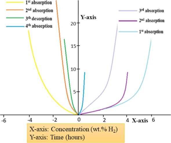
Room temperature H2 sorption kinetics of polyaniline nanospheres [130]. (Adapted from Niemann et al., Nanosc. Tech. (2008) 950967 under CCA license.)
2.6. Conclusions and future outlook
With developing concerns about atmospheric changes and consumption of non-sustainable power sources, a visualized hydrogen economy stays a feasible option in contrast to other energy sources. In this review, different solid-state H2 storage materials have been investigated. To accomplish the H2 economy, its storage remains the interest, as traditional storage frameworks may not be effective and safe for several onboard applications.
To diminish the concern of the future fuel, the hydrogen has to be used in the right direction and efficient storage systems need to be developed or previously developed systems are required to be modified to tackle the depleting fossil fuel concern.
The article discusses numerous nanomaterials and their substitutes as the potential systems. The performance of these depends upon the properties and operating conditions of the system. Chemical storage systems including complex and metal hydrides are promising but exhibit poor reversibility and cost-viability. Physical adsorption based on carbonaceous materials and different permeable materials with the high surface area has expanded multiple research fields due to its simple reversibility and efficient kinetics. However, low operating temperature is ideal for porous material hydrogen uptake. To improve the system performance, a metal-based catalysts may be induced into the adsorbent surface to enhance the hydrogen spillover effect and ion-ion interactions. Furthermore, volumetric and gravimetric techniques may be used to test the hydrogen sorption capabilities of the system. Both the techniques follow different mechanisms but the results are the same.
Difficulties of the solid-state hydrogen storage systems should be progressively researched to meet on-board targets given by the United States Department of Energy. It is anticipated that new methodologies must develop for solid-state H2 storage to add to the effective activity of hydrogen vision.
Declarations
Author contribution statement
All authors listed have significantly contributed to the development and the writing of this article.
Funding statement
The authors would like to thank TEQIP-III (MHRD, Govt. of India) for their support.
Competing interest statement
The authors declare no conflict of interest.
Additional information
No additional information is available for this paper.
References
- 1.Eberle U., Felderhoff M., Schueth F. Chemical and physical solutions for hydrogen storage. Angew. Chem., Int. Ed. 2009;48:6608–6630. doi: 10.1002/anie.200806293. [DOI] [PubMed] [Google Scholar]
- 2.Schlapbach L., Züttel A. World Scientific; 2011. Hydrogen-Storage Materials for Mobile Applications. [DOI] [PubMed] [Google Scholar]
- 3.Rowsell J.L., Yaghi O.M. Strategies for hydrogen storage in metal–organic frameworks. Angew. Chem., Int. Ed. 2005;44:4670–4679. doi: 10.1002/anie.200462786. [DOI] [PubMed] [Google Scholar]
- 4.Yang J., Sudik A., Wolverton C., Siegel D.J. High capacity hydrogen storage materials: attributes for automotive applications and techniques for materials discovery. Chem. Soc. Rev. 2010;39:656–675. doi: 10.1039/b802882f. [DOI] [PubMed] [Google Scholar]
- 5.Panella B., Hirscher M., Roth S. Hydrogen adsorption in different carbon nanostructures. Carbon. 2005;43:2209–2214. [Google Scholar]
- 6.Hirscher M., Panella B. Hydrogen storage in metal–organic frameworks. Scr. Mater. 2007;56:809–812. [Google Scholar]
- 7.Berry G.D., Pasternak A.D., Rambach G.D., Smith J.R., Schock R.N. Hydrogen as a future transportation fuel. Energy Policy. 1996;21:289–303. [Google Scholar]
- 8.Piel W.J. Transportation fuels of the future? Fuel Process. Technol. 2001;71:167–179. [Google Scholar]
- 9.Farrell A.E., Keith D.W., Corbett J.J. A strategy for introducing hydrogen into transportation. Energy Policy. 2003;31:1357–1367. [Google Scholar]
- 10.Zhou L. Progress and problems in hydrogen storage methods. Renew. Sustain. Energy Rev. 2005;9:395–408. [Google Scholar]
- 11.Dong J., Wang X., Xu H., Zhao Q., Li J. Hydrogen storage in several microporous zeolites. Int. J. Hydrog. Energy. 2007;32:4998–5004. [Google Scholar]
- 12.Germain J., Fréchet J.M., Svec F. Nanoporous polymers for hydrogen storage. Science. 2009;5:1098–1111. doi: 10.1002/smll.200801762. [DOI] [PubMed] [Google Scholar]
- 13.Yang S.J., Jung H., Kim T., Park C.R. Recent advances in hydrogen storage technologies based on nanoporous carbon materials. Prog. Nat. Sci. 2012;22:631–638. [Google Scholar]
- 14.Wang H., Gao Q., Hu J. High hydrogen storage capacity of porous carbons prepared by using activated carbon. J. Am. Chem. Soc. 2009;131:7016–7022. doi: 10.1021/ja8083225. [DOI] [PubMed] [Google Scholar]
- 15.Hu B., Wang K., Wu L., Yu S.-H., Antonietti M., Titirici M.-M. Engineering carbon materials from the hydrothermal carbonization process of biomass. Anal. Methods. 2010;22:813–828. doi: 10.1002/adma.200902812. [DOI] [PubMed] [Google Scholar]
- 16.Bogdanovic B., Brand R.A., Marjanovic A., Schwickardi M., Tölle J. Metal-doped sodium aluminium hydrides as potential new hydrogen storage materials. J. Alloys Compd. 2000;302:36–58. [Google Scholar]
- 17.Eigen N., Keller C., Dornheim M., Klassen T., Bormann R. Industrial production of light metal hydrides for hydrogen storage. Scr. Mater. 2007;56:847–851. [Google Scholar]
- 18.Eigen N., Gosch F., Dornheim M., Klassen T., Bormann R. Improved hydrogen sorption of sodium alanate by optimized processing. J. Alloys Compd. 2008;465:310–316. [Google Scholar]
- 19.Eigen N., Kunowsky M., Klassen T., Bormann R. Synthesis of NaAlH4-based hydrogen storage material using milling under low pressure hydrogen atmosphere. J. Alloys Compd. 2007;430:350–355. [Google Scholar]
- 20.Baldé C.P. Utrecht University; 2008. Sodium Alanate Nanoparticles for Hydrogen Storage. Ph.D. thesis. [DOI] [PubMed] [Google Scholar]
- 21.Bureau J.-C., Bastide J.-P., Bonnetot B., Eddaoudi H. Etude spectrometrique infrarouge et raman du tetrahydridoaluminate de sodium NaAlH4 solide. Mater. Res. Bull. 1985;20:93–98. [Google Scholar]
- 22.Li L., Xu C., Chen C., Wang Y., Jiao L., Yuan H. Sodium alanate system for efficient hydrogen storage. Int. J. Hydrog. Energy. 2013;38:8798–8812. [Google Scholar]
- 23.Ren J., Musyoka N.M., Langmi H.W, Mathe M., Liao S. Current research trends and perspectives on materials-based hydrogen storage solutions: a critical review. Int. J. Hydrog. Energy. 2017;42:289–311. [Google Scholar]
- 24.Baldé C.P., Hereijgers B.P., Bitter J.H., Jong K.P.d. Sodium alanate nanoparticles- linking size to hydrogen storage properties. J. Am. Chem. Soc. 2008;130:6761–6765. doi: 10.1021/ja710667v. [DOI] [PubMed] [Google Scholar]
- 25.Bahmanpour H., Lin K.-S., Mai Y.-J., Chiu S.-W., Yang J.-H., Chan S.L.I. Synthesis and characterization of metal hydride/carbon aerogel composites for hydrogen storage. J. Nanomater. 2012;2012 [Google Scholar]
- 26.Liu B., Li Z. A review: hydrogen generation from borohydride hydrolysis reaction. J. Power Sources. 2009;187:527–534. [Google Scholar]
- 27.Clasen H. Alanat-synthese aus den elementen und ihre bedeutung. Angew. Chem., Int. Ed. 1961;73:322–331. [Google Scholar]
- 28.Ashby E., Brendel G., Redman H. Direct synthesis of complex metal hydrides. Inorg. Chem. 1963;2:499–504. [Google Scholar]
- 29.Zaluski L., Zaluska A., Ström-Olsen J. Nanocrystalline metal hydrides. J. Alloys Compd. 1997;253:70–79. [Google Scholar]
- 30.Jensen C.M., Zidan R., Mariels N., Hee A., Hagen C. Advanced titanium doping of sodium aluminum hydride:: segue to a practical hydrogen storage material? Int. J. Hydrog. Energy. 1999;24:461–465. [Google Scholar]
- 31.Zidan R.A., Takara S., Hee A.G., Jensen C.M. Hydrogen cycling behavior of zirconium and titanium–zirconium-doped sodium aluminum hydride. J. Alloys Compd. 1999;285:119–122. [Google Scholar]
- 32.Bogdanović B., Felderhoff M., Kaskel S., Pommerin A., Schlichte K., Schueth F. Improved hydrogen storage properties of Ti-doped sodium alanate using Titanium nanoparticles as doping agents. Anal. Methods. 2003;15:1012–1015. [Google Scholar]
- 33.Fan X., Xiao X., Chen L., Han L., Li S., Ge H., Wang Q. Thermodynamics, kinetics, and modeling investigation on the dehydrogenation of CeAl4-Doped NaAlH4 hydrogen storage material. J. Phys. C. 2011;115:22680–22687. [Google Scholar]
- 34.Li L., Qiu F., Wang Y., Liu G., Xu Y., An C., Wang Y., Jiao L., Yuan H. TiN catalyst for the reversible hydrogen storage performance of sodium alanate system. J. Mater. Chem. 2012;22:13782–13787. [Google Scholar]
- 35.Pitt M., Vullum P., Sørby M., Emerich H., Paskevicius M., Buckley C., Gray E.M., Walmsley J., Holmestad R., Hauback B. A structural review of nanoscopic AlTMx phase formation in the TMCln enhanced NaAlH4 system. J. Alloys Compd. 2012;527:16–24. [Google Scholar]
- 36.Verkuijlen M.H., van Bentum P.J.M., Zabara O., Fichtner M., Kentgens A.P. 27Al, 23Na, and 45Sc solid-state NMR studies of ScCl3-doped NaAlH4. J. Phys. C. 2011;115:13100–13106. [Google Scholar]
- 37.Lin S.S.-Y., Yang J., Kung H.H. Transition metal-decorated activated carbon catalysts for dehydrogenation of NaAlH4. Int. J. Hydrog. Energy. 2012;37:2737–2741. [Google Scholar]
- 38.Sandrock G. A panoramic overview of hydrogen storage alloys from a gas reaction point of view. J. Alloys Compd. 1999;293:877–888. [Google Scholar]
- 39.Bogdanović B., Bohmhammel K., Christ B., Reiser A., Schlichte K., Vehlen R., Wolf U. Thermodynamic investigation of the magnesium–hydrogen system. J. Alloys Compd. 1999;282:84–92. [Google Scholar]
- 40.Chen P., Xiong Z., Luo J., Lin J., Tan K.L. Interaction of hydrogen with metal nitrides and imides. Nature. 2002;420:302. doi: 10.1038/nature01210. [DOI] [PubMed] [Google Scholar]
- 41.Luo W. (LiNH2–MgH2): a viable hydrogen storage system. J. Alloys Compd. 2004;381:284–287. [Google Scholar]
- 42.Sakintuna B., Lamari-Darkrim F., Hirscher M. Metal hydride materials for solid hydrogen storage: a review. Int. J. Hydrog. Energy. 2007;32:1121–1140. [Google Scholar]
- 43.Orimo S.-i., Nakamori Y., Eliseo J.R., Züttel A., Jensen C.M. Complex hydrides for hydrogen storage. Chem. Rev. 2007;107:4111–4132. doi: 10.1021/cr0501846. [DOI] [PubMed] [Google Scholar]
- 44.Chłopek K., Frommen C., Léon A., Zabara O., Fichtner M. Synthesis and properties of magnesium tetrahydroborate, Mg(BH4)2. J. Mater. Chem. 2007;17:3496–3503. [Google Scholar]
- 45.Züttel A., Rentsch S., Fischer P., Wenger P., Sudan P., Mauron P., Emmenegger C. Hydrogen storage properties of LiBH4. J. Alloys Compd. 2003;356:515–520. [Google Scholar]
- 46.Vajo J.J., Olson G.L. Hydrogen storage in destabilized chemical systems. Scr. Mater. 2007;56:829–834. [Google Scholar]
- 47.Vajo J.J., Skeith S.L., Mertens F. Reversible storage of hydrogen in destabilized LiBH4. J. Phys. Chem. B. 2005;109:3719–3722. doi: 10.1021/jp040769o. [DOI] [PubMed] [Google Scholar]
- 48.Li H.-W., Yan Y., Orimo S.-i., Züttel A., Jensen C.M. Recent progress in metal borohydrides for hydrogen storage. Energies. 2011;4:185–214. [Google Scholar]
- 49.Marrero-Alfonso E.Y., Beaird A.M., Davis T.A., Matthews M.A. Iecr. Ind. Eng. Chem. Res. 2009;48:3703–3712. [Google Scholar]
- 50.Finholt A., Barbaras G.D., Barbaras G.K., Urry G., Wartik T., Schlesinger H. The preparation of sodium and calcium aluminium hydrides. J. Inorg. Nucl. Chem. 1955;1:317–325. [Google Scholar]
- 51.Yadav M., Xu Q. Liquid-phase chemical hydrogen storage materials. Energy Environ. Sci. 2012;5:9698–9725. [Google Scholar]
- 52.Shang Y., Chen R. Hydrogen storage via the hydrolysis of NaBH4 basic solution: optimization of NaBH4 concentration. Energy Fuels. 2006;20:2142–2148. [Google Scholar]
- 53.Prosini P.P., Gislon P. A hydrogen refill for cellular phone. J. Power Sources. 2006;161:290–293. [Google Scholar]
- 54.Murugesan S., Subramanian V.R. Effects of acid accelerators on hydrogen generation from solid sodium borohydride using small scale devices. J. Power Sources. 2009;187:216–223. [Google Scholar]
- 55.Demirci U.B., Akdim O., Andrieux J., Hannauer J., Chamoun R., Miele P. Sodium borohydride hydrolysis as hydrogen generator: issues, state of the art and applicability upstream from a fuel cell. Fuel Cells. 2010;10:335–350. [Google Scholar]
- 56.Tsai C., Chen H., Liu R., Lee J.-F., Chang S., Weng B. Magnetically recyclable Fe@Co core-shell catalysts for dehydrogenation of sodium borohydride in fuel cells. Int. J. Hydrog. Energy. 2012;37:3338–3343. [Google Scholar]
- 57.Brown H.C., Brown C.A. New, highly active metal catalysts for the hydrolysis of borohydride. J. Am. Chem. Soc. 1962;84:1493–1494. [Google Scholar]
- 58.Amendola S.C., Sharp-Goldman S.L., Janjua M.S., Spencer N.C., Kelly M.T., Petillo P.J., Binder M. A safe, portable, hydrogen gas generator using aqueous borohydride solution and Ru catalyst. Int. J. Hydrog. Energy. 2000;25:969–975. [Google Scholar]
- 59.Amendola S.C., Sharp-Goldman S.L., Janjua M.S., Kelly M.T., Petillo P.J., Binder M. An ultrasafe hydrogen generator: aqueous, alkaline borohydride solutions and Ru catalyst. J. Power Sources. 2000;85:186–189. [Google Scholar]
- 60.Kojima Y., Suzuki K.-i., Fukumoto K., Sasaki M., Yamamoto T., Kawai Y., Hayashi H. Hydrogen generation using sodium borohydride solution and metal catalyst coated on metal oxide. Int. J. Hydrog. Energy. 2002;27:1029–1034. [Google Scholar]
- 61.Rangel C., Fernandes V.R., Silva R., Bonnetot B., Laversenne L., Buni A., Minkina V., Perrin J. 2007. Production of hydrogen by borohydride: in search of low cost non-noble efficient catalyst. [Google Scholar]
- 62.Hannauer J., Demirci U., Pastor G., Geantet C., Herrmann J., Miele P. Hydrogen release through catalyzed methanolysis of solid sodium borohydride. Energy Environ. Sci. 2010;3:1796–1803. [Google Scholar]
- 63.Brown H.C., Mead E.J., Subba Rao B. A study of solvents for sodium borohydride and the effect of solvent and the metal ion on borohydride reductions1. J. Am. Chem. Soc. 1955;77:6209–6213. [Google Scholar]
- 64.Andrieux J., Demirci U.B., Hannauer J., Gervais C., Goutaudier C., Miele P. Spontaneous hydrolysis of sodium borohydride in harsh conditions. Int. J. Hydrog. Energy. 2011;36:224–233. [Google Scholar]
- 65.Hannauer J., Demirci U., Geantet C., Herrmann J., Miele P. Enhanced hydrogen release by catalyzed hydrolysis of sodium borohydride–ammonia borane mixtures: a solution-state 11B NMR study. Phys. Chem. Chem. Phys. 2011;13:3809–3818. doi: 10.1039/c0cp02090g. [DOI] [PubMed] [Google Scholar]
- 66.Marrero-Alfonso E.Y., Gray J.R., Davis T.A., Matthews M.A. Minimizing water utilization in hydrolysis of sodium borohydride: the role of sodium metaborate hydrates. Int. J. Hydrog. Energy. 2007;32:4723–4730. [Google Scholar]
- 67.Atiyeh H.K., Davis B.R. Separation of sodium metaborate from sodium borohydride using nanofiltration membranes for hydrogen storage application. Int. J. Hydrog. Energy. 2007;32:229–236. [Google Scholar]
- 68.Çakanyıldırım Ç., Gürü M. Hydrogen cycle with sodium borohydride. Int. J. Hydrog. Energy. 2008;33:4634–4639. [Google Scholar]
- 69.Šljukić B., Santos D.M., Sequeira C.A., Banks C.E. Analytical monitoring of sodium borohydride. Anal. Methods. 2013;5:829–839. [Google Scholar]
- 70.Kojima Y., Haga T. Recycling process of sodium metaborate to sodium borohydride. Int. J. Hydrog. Energy. 2003;28:989–993. [Google Scholar]
- 71.Li Z.P., Liu B.H., Morigasaki N., Suda S. Preparation of potassium borohydride by a mechano-chemical reaction of saline hydrides with dehydrated borate through ball milling. J. Am. Chem. Soc. 2003;354:243–247. [Google Scholar]
- 72.Li Z.P., Morigazaki N., Liu B., Suda S. Preparation of sodium borohydride by the reaction of MgH2 with dehydrated borax through ball milling at room temperature. J. Am. Chem. Soc. 2003;349:232–236. [Google Scholar]
- 73.Ouyang L., Zhong H., Li H.-W., Zhu M. A recycling hydrogen supply system of NaBH4 based on a facile regeneration process: a review. Inorgs. 2018;6:10. [Google Scholar]
- 74.Santos D., Sequeira C. On the electrosynthesis of sodium borohydride. Int. J. Hydrog. Energy. 2010;35:9851–9861. [Google Scholar]
- 75.Liu C.-H., Chen B.-H., Lee D.-J., Ku J.-R., Tsau F. Trimethyl borate regenerated from spent sodium borohydride after hydrogen production. Ind. Eng. Chem. Res. 2010;49:9864–9869. [Google Scholar]
- 76.Wu Y., Kelly M.T., Ortega J.V. August 2004. Review of chemical processes for the synthesis of sodium borohydride. DoE Report. [Google Scholar]
- 77.Calabretta D.L., Davis B.R. Investigation of the anhydrous molten Na–B–O–H system and the concept: electrolytic hydriding of sodium boron oxide species. J. Power Sources. 2007;164:782–791. [Google Scholar]
- 78.Rosi N.L., Eckert J., Eddaoudi M., Vodak D.T., Kim J., O'keeffe M., Yaghi O.M. Hydrogen storage in microporous metal-organic frameworks. Science. 2003;300:1127–1129. doi: 10.1126/science.1083440. [DOI] [PubMed] [Google Scholar]
- 79.Ardelean O., Blanita G., Borodi G., Lazar M.D., Misan I., Coldea I., Lupu D. Volumetric hydrogen adsorption capacity of densified MIL-101 monoliths. Int. J. Hydrog. Energy. 2013;38:7046–7055. [Google Scholar]
- 80.Carrington K.R., Barcelo S., Karkamkar A., Purewal J., Ma S., Zhou H.-C., Dantzer P., Ott K., Burrell T., Semeslberger T. Efficiency and Renewable Energy, US Department of Energy-Office of Energy; 2012. Recommended best practices for the characterization of storage properties of hydrogen storage materials. [Google Scholar]
- 81.Ren J., Langmi H.W., North B.C., Mathe M. Review on processing of metal–organic framework (MOF) materials towards system integration for hydrogen storage. Int. J. Energy Res. 2015;39:607–620. [Google Scholar]
- 82.S U. 2009. Targets for on-board hydrogen storage systems: current R&D focus is on 2015 targets with potential to meet ultimate targets. [Google Scholar]
- 83.Kunowsky M., Marco-Lozar J.P., Cazorla-Amorós D., Linares-Solano A. Scale-up activation of carbon fibres for hydrogen storage. Int. J. Hydrog. Energy. 2010;35:2393–2402. [Google Scholar]
- 84.Marco-Lozar J., Juan-Juan J., Suárez-García F., Cazorla-Amorós D., Linares-Solano A. MOF-5 and activated carbons as adsorbents for gas storage. Int. J. Hydrog. Energy. 2012;37:2370–2381. [Google Scholar]
- 85.Kaye S.S., Dailly A., Yaghi O.M., Long J.R. Impact of preparation and handling on the hydrogen storage properties of Zn4O (1,4-benzenedicarboxylate)3 (MOF-5) J. Am. Chem. Soc. 2007;129:14176–14177. doi: 10.1021/ja076877g. [DOI] [PubMed] [Google Scholar]
- 86.Akhtar F., Andersson L., Ogunwumi S., Hedin N., Bergström L. Structuring adsorbents and catalysts by processing of porous powders. J. Eur. Ceram. Soc. 2014;34:1643–1666. [Google Scholar]
- 87.Ren J., North B.C. Shaping porous materials for hydrogen storage applications: a review. J. Technol. Innov. Renew. Energy. 2014;3:12–20. [Google Scholar]
- 88.Zacher D., Shekhah O., Wöll C., Fischer R.A. Thin films of metal–organic frameworks. Chem. Soc. Rev. 2009;38:1418–1429. doi: 10.1039/b805038b. [DOI] [PubMed] [Google Scholar]
- 89.Fletcher A.J., Thomas K.M., Rosseinsky M.J. Flexibility in metal-organic framework materials: impact on sorption properties. J. Solid State Chem. 2005;178:2491–2510. [Google Scholar]
- 90.Yang J., Grzech A., Mulder F.M., Dingemans T.J. Methyl modified MOF-5: a water stable hydrogen storage material. Chem. Commun. 2011;47:5244–5246. doi: 10.1039/c1cc11054c. [DOI] [PubMed] [Google Scholar]
- 91.Yang S.J., Choi J.Y., Chae H.K., Cho J.H., Nahm K.S., Park C.R. Preparation and enhanced hydrostability and hydrogen storage capacity of CNT@ MOF-5 hybrid composite. Chem. Commun. 2009;21:1893–1897. [Google Scholar]
- 92.Yoo Y., Varela-Guerrero V., Jeong H.-K. Isoreticular metal- organic frameworks and their membranes with enhanced crack resistance and moisture stability by surfactant-assisted drying. Langmuir. 2011;27:2652–2657. doi: 10.1021/la104775d. [DOI] [PubMed] [Google Scholar]
- 93.Li H., Shi W., Zhao K., Li H., Bing Y., Cheng P. Enhanced hydrostability in Ni-doped MOF-5. Inorg. Chem. 2012;51:9200–9207. doi: 10.1021/ic3002898. [DOI] [PubMed] [Google Scholar]
- 94.Cavka J.H., Jakobsen S., Olsbye U., Guillou N., Lamberti C., Bordiga S., Lillerud K.P. A new zirconium inorganic building brick forming metal organic frameworks with exceptional stability. J. Am. Chem. Soc. 2008;130:13850–13851. doi: 10.1021/ja8057953. [DOI] [PubMed] [Google Scholar]
- 95.Chui S.S.-Y., Lo S.M.-F., Charmant J.P., Orpen A.G., Williams I.D. A chemically functionalizable nanoporous material [Cu3(TMA)2(H2O)3]n. Science. 1999;283:1148–1150. doi: 10.1126/science.283.5405.1148. [DOI] [PubMed] [Google Scholar]
- 96.Férey G., Mellot-Draznieks C., Serre C., Millange F., Dutour J., Surblé S., Margiolaki I. A chromium terephthalate-based solid with unusually large pore volumes and surface area. Science. 2005;309:2040–2042. doi: 10.1126/science.1116275. [DOI] [PubMed] [Google Scholar]
- 97.Nijkamp M., Raaymakers J., Van Dillen A., De Jong K. Hydrogen storage using physisorption–materials demands. Appl. Phys. A. 2001;72:619–623. [Google Scholar]
- 98.Rowsell J.L., Millward A.R., Park K.S., Yaghi O.M. Hydrogen sorption in functionalized metal–organic frameworks. J. Am. Chem. Soc. 2004;126:5666–5667. doi: 10.1021/ja049408c. [DOI] [PubMed] [Google Scholar]
- 99.Langmi H.W., Ren J., North B., Mathe M., Bessarabov D. Hydrogen storage in metal-organic frameworks: a review. Electrochim. Acta. 2014;128:368–392. [Google Scholar]
- 100.Latroche M., Surblé S., Serre C., Mellot-Draznieks C., Llewellyn P.L., Lee J.-H., Chang J.-S., Jhung S.H., Férey G. Hydrogen storage in the giant-pore metal–organic frameworks MIL-100 and MIL-101. Angew. Chem., Int. Ed. 2006;118:8407–8411. doi: 10.1002/anie.200600105. [DOI] [PubMed] [Google Scholar]
- 101.Rowsell J.L., Yaghi O.M. Effects of functionalization, catenation, and variation of the metal oxide and organic linking units on the low-pressure hydrogen adsorption properties of metal–organic frameworks. J. Am. Chem. Soc. 2006;128:1304–1315. doi: 10.1021/ja056639q. [DOI] [PubMed] [Google Scholar]
- 102.Wong-Foy A.G., Matzger A.J., Yaghi O.M. Exceptional H2 saturation uptake in microporous Metal–Organic Frameworks. J. Am. Chem. Soc. 2006;128:3494–3495. doi: 10.1021/ja058213h. [DOI] [PubMed] [Google Scholar]
- 103.Thomas K.M. Adsorption and desorption of hydrogen on metal–organic framework materials for storage applications: comparison with other nanoporous materials. Dalton Trans. 2009:1487–1505. doi: 10.1039/b815583f. [DOI] [PubMed] [Google Scholar]
- 104.Chun H., Dybtsev D.N., Kim H., Kim K. Synthesis, X-ray crystal structures, and gas sorption properties of pillared square grid nets based on paddle-wheel motifs: implications for hydrogen storage in porous materials. Chem. Eur. J. 2005;11:3521–3529. doi: 10.1002/chem.200401201. [DOI] [PubMed] [Google Scholar]
- 105.Yang Q., Zhong C. Understanding hydrogen adsorption in metal–organic frameworks with open metal sites: a computational study. J. Phys. Chem. B. 2006;110:655–658. doi: 10.1021/jp055908w. [DOI] [PubMed] [Google Scholar]
- 106.Frost H., Düren T., Snurr R.Q. Effects of surface area, free volume, and heat of adsorption on hydrogen uptake in metal–organic frameworks. J. Phys. Chem. B. 2006;110:9565–9570. doi: 10.1021/jp060433+. [DOI] [PubMed] [Google Scholar]
- 107.Ren J., Musyoka N.M., Langmi H.W., North B.C., Mathe M., Kang X. Fabrication of core–shell MIL-101 (Cr)@ UiO-66 (Zr) nanocrystals for hydrogen storage. Int. J. Hydrog. Energy. 2014;39:14912–14917. [Google Scholar]
- 108.Burrows A.D. Mixed-component metal–organic frameworks (MC-MOFs): enhancing functionality through solid solution formation and surface modifications. CrystEngComm. 2011;13:3623–3642. [Google Scholar]
- 109.Jiang H., Feng Y., Chen M., Wang Y. Synthesis and hydrogen-storage performance of interpenetrated MOF-5/MWCNTs hybrid composite with high mesoporosity. Int. J. Hydrog. Energy. 2013;38:10950–10955. [Google Scholar]
- 110.Xu C., Yang J., Veenstra M., Sudik A., Purewal J., Ming Y., Hardy B., Warner J., Maurer S., Müeller U. Hydrogen permeation and diffusion in densified MOF-5 pellets. Int. J. Hydrog. Energy. 2013;38:3268–3274. [Google Scholar]
- 111.Purewal J., Liu D., Yang J., Sudik A., Siegel D., Maurer S., Müller U. Increased volumetric hydrogen uptake of MOF-5 by powder densification. Int. J. Hydrog. Energy. 2012;37:2723–2727. [Google Scholar]
- 112.Dailly A., Poirier E. Evaluation of an industrial pilot scale densified MOF-177 adsorbent as an on-board hydrogen storage medium. Energy Environ. Sci. 2011;4:3527–3534. [Google Scholar]
- 113.Boudart M., Vannice M., Benson J.E. Adlineation, portholes and spillover. Z. Phys. Chem. 1969;64:171–177. [Google Scholar]
- 114.Prins R. Hydrogen spillover. Facts and fiction. Chem. Rev. 2012;112:2714–2738. doi: 10.1021/cr200346z. [DOI] [PubMed] [Google Scholar]
- 115.Luzan S.M., Talyzin A. Hydrogen adsorption in Pt catalyst/MOF-5 materials. Microporous Mesoporous Mater. 2010;135:201–205. [Google Scholar]
- 116.Campesi R., Cuevas F., Latroche M., Hirscher M. Hydrogen spillover measurements of unbridged and bridged metal–organic frameworks revisited. Phys. Chem. Chem. Phys. 2010;12:10457–10459. doi: 10.1039/c0cp00037j. [DOI] [PubMed] [Google Scholar]
- 117.Spek A.L. Platon squeeze: a tool for the calculation of the disordered solvent contribution to the calculated structure factors. Acta Crystallogr., Sect. C. 2015;71:9–18. doi: 10.1107/S2053229614024929. [DOI] [PubMed] [Google Scholar]
- 118.Katoch A., Bhardwaj R., Goyal N., Gautam S. Synthesis, structural and optical study of Ni-doped Metal-organic framework for adsorption based chemical sensor application. Vacuum. 2018;158:249–256. [Google Scholar]
- 119.Chen P., Zhang H.-B., Lin G.-D., Hong Q., Tsai K. Growth of carbon nanotubes by catalytic decomposition of CH4 or CO on a Ni–MgO catalyst. Carbon. 1997;35:1495–1501. [Google Scholar]
- 120.Liu H., Li Y. Modified carbon nanotubes for hydrogen storage at moderate pressure and room temperature. Fuller. Nanotub. Carbon Nanostructures. 2020:1–8. [Google Scholar]
- 121.Darkrim F.L., Malbrunot P., Tartaglia G. Review of hydrogen storage by adsorption in carbon nanotubes. Int. J. Hydrog. Energy. 2002;27:193–202. [Google Scholar]
- 122.Chen P., Wu X., Lin J., Tan K. High H2 uptake by alkali-doped carbon nanotubes under ambient pressure and moderate temperatures. Science. 1999;285:91–93. doi: 10.1126/science.285.5424.91. [DOI] [PubMed] [Google Scholar]
- 123.Pham-Huu C., Keller N., Ehret G., Ledoux M.J. The first preparation of silicon carbide nanotubes by shape memory synthesis and their catalytic potential. J. Catal. 2001;200:400–410. [Google Scholar]
- 124.Yu W.-J., Liu C., Hou P.-X., Zhang L., Shan X.-Y., Li F., Cheng H.-M. Lithiation of silicon nanoparticles confined in carbon nanotubes. ACS Nano. 2015;9:5063–5071. doi: 10.1021/acsnano.5b00157. [DOI] [PubMed] [Google Scholar]
- 125.Menon M., Richter E., Mavrandonakis A., Froudakis G., Andriotis A.N. Structure and stability of SiC nanotubes. Phys. Rev. B. 2004;69 [Google Scholar]
- 126.Wang L., Lee K., Sun Y.-Y., Lucking M., Chen Z., Zhao J.J., Zhang S.B. Graphene oxide as an ideal substrate for hydrogen storage. ACS Nano. 2009;3:2995–3000. doi: 10.1021/nn900667s. [DOI] [PubMed] [Google Scholar]
- 127.Adams B.D., Chen A. The role of palladium in a hydrogen economy. Mater. Today. 2011;14:282–289. [Google Scholar]
- 128.Aristizabal K., Katzensteiner A., Leoni M., Mücklich F., Suárez S. Evolution of the lattice defects and crystalline domain size in carbon nanotube metal matrix composites processed by severe plastic deformation. Mater. Charact. 2019;154:344–352. [Google Scholar]
- 129.Cho S.J., Song K.S., Kim J.W., Kim T.H., Choo K. Hydrogen sorption in HCl-treated polyaniline and polypyrrole: new potential hydrogen storage media. Fuel. Chem. Div. 2002;47:790–791. [Google Scholar]
- 130.Niemann M.U., Srinivasan S.S., Phani A.R., Kumar A., Goswami D.Y., Stefanakos E.K. Nanomaterials for hydrogen storage applications: a review. J. Nanomater. 2008;2008 [Google Scholar]
- 131.Fan Y.-Y., Kaufmann A., Mukasyan A., Varma A. Single- and multi-wall carbon nanotubes produced using the floating catalyst method: synthesis, purification and hydrogen up-take. Carbon. 2006;44:2160–2170. [Google Scholar]