Abstract
Medical ultrasound is extensively used to define tissue textures and to characterize lesions, and it is the modality of choice for detection and follow-up assessment of thyroid diseases. Classical medical ultrasound procedures are performed manually by an occupational operator with a hand-held ultrasound probe. These procedures require high physical and cognitive burden and yield clinical results that are highly operator-dependent, therefore frequently diminishing trust in ultrasound imaging data accuracy in repetitive assessment. A robotic ultrasound procedure, on the other hand, is an emerging paradigm integrating a robotic arm with an ultrasound probe. It achieves an automated or semi-automated ultrasound scanning by controlling the scanning trajectory, region of interest, and the contact force. Therefore, the scanning becomes more informative and comparable in subsequent examinations over a long-time span. In this work, we present a technique for allowing operators to reproduce reliably comparable ultrasound images with the combination of predefined trajectory execution and real-time force feedback control. The platform utilized features a 7-axis robotic arm capable of 6-DoF force-torque sensing and a linear-array ultrasound probe. The measured forces and torques affecting the probe are used to adaptively modify the predefined trajectory during autonomously performed examinations and probe-phantom interaction force accuracy is evaluated. In parallel, by processing and combining ultrasound B-Mode images with probe spatial information, structural features can be extracted from the scanning volume through a 3D scan. The validation was performed on a tissue-mimicking phantom containing thyroid features, and we successfully demonstrated high image registration accuracy between multiple trials.
Keywords: robotic ultrasound, 3D ultrasound, ultrasound image registration, force control, motion planning, 3D imaging
I. BACKGROUND
Ultrasonography is a medical imaging modality commonly used for point of care medical examinations, which allows for non-invasive, non-ionizing and cost-effective use on a wide range of patients. Traditionally the examination output data consists of a series of 2D images being cross-sections of tissue structure, which imposes large cognitive load on an ultrasonographer and requires expertise in manual probe operation and domain knowledge to spot abnormal findings and plan their further exploration during the procedure. Additionally, high operator-variability makes it difficult to compare subsequent examinations results.
These limitations undermine the acceptance of ultrasound imaging for both accurate detection and reliable comparison of subsequent examinations results which is crucial for treatment planning. New scanning methods addressing these issues could leverage the effectiveness of ultrasound used for detecting common social-wide medical conditions such as abnormal changes in thyroid. The number of thyroid cancer cases in the United States has increased significantly over recent years [1]. Moreover, on average, 50% of Americans aged 50 or above develop thyroid nodules. This problem is also affecting the younger generation due to environmental changes and lifestyle [2]. The prevalence of malignant thyroid nodules is between 4-6.5% on average. With 60% of surgery procedures turning afterwards not to be needed, the correct malignancy classification using ultrasound examination and biopsies data remains a challenge [3]. There is a strong need to create a system which allows for precise and repeatable examinations to reduce the false-positive rate and facilitate more effective diagnosis.
A 3D ultrasound scanning is an emerging technique already used in obstetrics, cardiology, surgical guidance, vascular imaging, orthopedics, thyroid, and anesthesia, which offers better illustration of the scanning region, but requires high-end expensive probes and premium ultrasound stations[4]-[10]. It facilitates comparison of images and reduces the risk of overlooking concealed features. Similar values, however, can also be achieved with a 3D image composed from a series of 2D images from conventional probes if probe spatial position and orientation are tracked. This approach is investigated by research groups focusing on automation or semi-automation of ultrasound procedures using robotic manipulation systems. The systems are being tested in both point of care and intraoperative ultrasound applications offering probe tracking and tissue interaction force sensing which paws the way to perform examinations in a standardized fashion [11]-[16], However, the technique making ultrasound scanning to be repeatable and reproducible has not been well explored.
II. METHODS
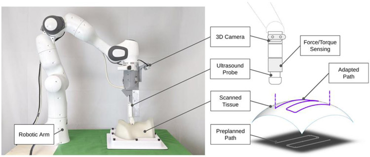
We introduce the robot-assisted ultrasound platform to enable repeatable repetitive scanning (Fig. 1). This platform comprises a robot arm attached to an ultrasound probe that provides the automatic scanning following the scanning path and parameters computed based on previous scans performed on the same patient. A RGB-D 3D camera can be used for registration between skin surface maps through multiple trials. The execution pipeline and workflow is formulated in four stages (Fig. 2): A) 3D Perception and Planning, B) Ultrasound Data Collection, C) 3D Ultrasound Data Generation and Processing and D) Follow-up assessment. In the first stage, 3D computer vision can determine phantom position and adjust preplanned trajectory. Next, robot executes the examination trajectory while maintaining probe-phantom contact surface and capturing ultrasound images. Finally, the 3D ultrasound data is reconstructed and later used for procedure reproducibility evaluation. The details of these procedure stages are discussed in the Subsections A-D. In this paper, we particularly focus on the execution of robot and associated ultrasound data processing related to Stages B-D
Fig. 1.
Robotic ultrasound scanning system and its components.
Fig. 2.
Workflow of robotic ultrasound procedure on thyroid.
A. 3D Perception and Planning
This stage provides preplanned trajectory based on the 3D camera data observations and predefined trajectory and anatomy models. The procedure begins with a robot moving to the RGBD image capturing pose, 3D image is captured and processed. Then a template object model is registered with the current observation by using Iterative Closes Point method (ICP), which computes the transformation between observation and model [17]. The transformation is used for relocating trajectory entry point and the plane model to the currently observed point cloud. Preplanned trajectory in the cartesian space is generated for x and y coordinates in the world frame. The z coordinate will be adjusted during the examination, x-y trajectory consists of a series of point-to-point motions, each having linear acceleration, constant motion and linear deacceleration phases as illustrated in the Fig. 3. Correspondingly, the computation of the current velocity in x and y axes demarked as Velnow falls to 3 cases (VelIVelIIVelIII) determined by the projection of the end-effector position on the path (Eqs 1–4).
Fig. 3.
Robotic Ultrasound Procedure Workflow
| (1) |
| (2) |
| (3) |
| (4) |
B. Robot Control and Ultrasound Data Collection
Data collection stage is accomplished by incorporating contact force feedback control to the preplanned path while simultaneously capturing ultrasound images. Robot end-effector is perpendicular to the world x-y plane (the examination table surface). To initiate the scanning procedure, the robot is first commanded to move from the image capturing pose to a point over the examination entry point. Once the probe reaches the phantom surface, the force sensed by the robot triggers the activation of force control. The ultrasound probe slides over phantom surface to cover the region of interest while maintaining predefined absolute target force level. This is achieved by using the Cartesian velocity controller incorporating feed forward trajectory scheduling in the lateral-elevation plane and a P controller with saturation for force control in the axial axis. The controller input being force error Ferror n describes as the difference between the absolute probe-tissue contact force and the target absolute contact force. Current Zveln cartesian velocity is an output of the P controller or a result of changing previous Zveln-1 by a maximum safe increment Δsafe if the controller velocity change to be commanded is greater than this value. This approach allows for continuous robot operation, which would be otherwise interrupted by cartesian motion command discontinuity errors signaled by the robot. During motion, ultrasound image acquisition is triggered and later combined with the corresponding probe-phantom contact force level and probe spatial information data expressed with respect to the robot base frame.
| (5) |
| (6) |
| (7) |
| (8) |
While this control approach does not incorporate feedback control for the x-y axes, robot internal control realizes this task avoiding arising x and y position errors in the cartesian velocity control mode.
c. 3D Ultrasound Data Generation & Image Processing
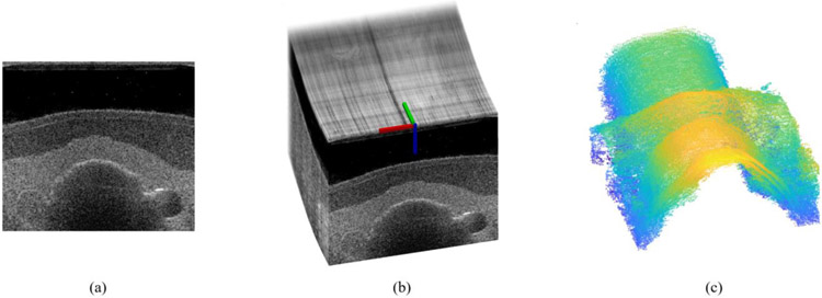
Generating 3D ultrasound data is critical or our experimental procedure repeatability evaluation and can offer significant image assessment simplification. The subsequent 2D B-mode images are matched with their corresponding probe spatial data, and a compounded 3D ultrasound image is created (Fig. 4b). One examination consists of 5 pairs of back and forth probe motion captured centrally along the neck region. An ultrasound swipe is a collection of ultrasound frames captured by a probe moving in one direction. A total of 10 ultrasound swipes are generated in the procedure for probe motion occurring back and forth along the predefined path.
Fig. 4.
A sample 2D ultrasound image (a); 3D ultrasound image composed from series of 2D ultrasound images and corresponding probe poses (b); thyroid region surface after edge detection and noise filtering operations (c)
Image processing is used to extract crucial anatomy information using 2D and compounded 3D ultrasound data, primarily tissue boundaries and objects of interest positions (Fig. 4c). These data can be used to facilitate future ultrasound image registration between subsequent trials. The edges of objects of interest present in the ultrasound images are extracted using the Canny filter and are transformed into a series of point clouds compounded together and processed with an outlier removal procedure. The resulting point clouds can be further segmented.
D. Assessment between Subsequent Swipes
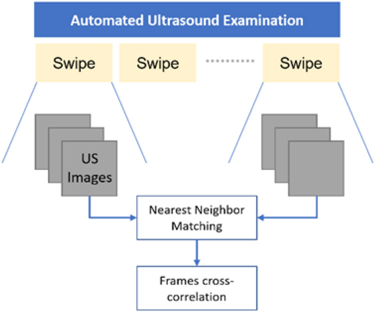
To evaluate robot acquisition repeatability within a single examination, we command the system to revisit the scanning locations 10 times by executing back and forth motion along phantom sagittal plane while tracking surface contact. Multiple comparable images are expected for every captured datapoint consisting of ultrasound image and robot pose. B-mode images are compared by matching frames from the first probe swipe with the corresponding images from another swipe in one procedure. Matching is performed by using frames spatial data to find nearest neighbors (Fig. 5).
Fig. 5.
Matching frames between ultrasound swipes
For each pair of matching frames A, B which have resolution m x n and mean image intensity values , 3D cross-correlation function is computed using the formula (9). It allows for computing the similarity between two images and can be used for procedure repeatability judgement.
| (9) |
E. Experimental Implementation
The hardware used consists of a 7 degree-of-freedom Franka Emika Panda Research robotic manipulator equipped with an Intel RealSense D435i 3D camera and an ATL L7-4 ultrasound probe attached to robot end-effector. Robot force sensing capabilities are used to control probe-phantom surface contact force during the examination. A CIRS thyroid ultrasound training phantom is a subject in the trials. Verasonics Vantage 128 research ultrasound system is used for ultrasound data acquisition. The real-time B-mode images were collected in 8 Hz and transferred to the robot controlling computer through the ROS topic. Robot end-effector translation speed during the acquisition was restricted to 1mm/s due to the ultrasound data collection constraints. However, motion with reliable force control for thyroid phantom surface is feasible up to 4mm/s.
III. RESULTS AND DISCUSSION
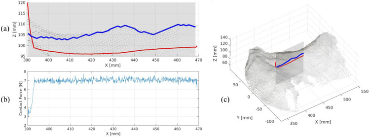
We demonstrate an autonomous probe operation using our control strategy. Figure 6 shows phantom point cloud surface and surface its 2D edge in a cross-section view, registered with a single swipe probe path after execution. As anticipated, actual executed path lies below the camera-measured phantom tissue surface which is understandable given the tissue elasticity. The measured neck surface, however, is rich in local shape artifacts which locally disturb the surface smoothness. These artifacts are primarily visible on a surface edge plotted in blue on (a) and might invalidate potential elasticity measurements relying on tissue collapsing properties. We recognize phantom semi-transparent silicon surface to be a primary source of these errors due to the 3D camera IR light projection failures and expect the surface measurements to be better when conducted on human subjects. We set the target contact force to be 7N to stabilize the data acquisition. The average measured force during image acquisition with force tracking was 7.04 N and 0.20 N for standard deviation. This is a satisfactory result for a robot on-board force sensing capability.
Fig. 6.
Probe path executed during the examination [red] with respect to the measured phantom tissue surface [blue] (a); Absolute probe-tissue contact force with respect to the x coordinate (b); executed path registered with the phantom surface point cloud (c).
Figure 7 presents imaging repeatability results showing data from multiple ultrasound swipes to find best correlated frames. Overall best (b, c) and worst (e, f) image cross-correlations are presented for two different reference frames (a, d). While frames within rows remain visually similar and depict the same neighborhood, we can observe a small out-of-plane shift between the reference image (d) and image (f) in the second row. We identify limited framerate as the main cause for these inaccuracies. Given the scanning speed of 1mm/s and ability to capture 8 frames/s on average, we expect the frame to be captured every 0.125mm, but the acquisition locations are not dictated a priori. This implies that the nearest neighbors found can theoretically have up to 0.0625mm position shift which can affect changes in the image content observed. Other sources of errors in the cross-correlation evaluation include robot repeatability limitations, potential uneven tissue deformations and the B-mode image noise itself.
Fig. 7.
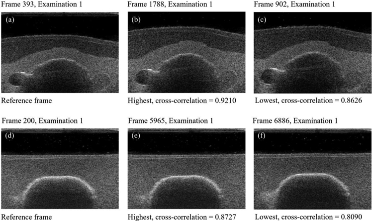
Selected reference frames (a, d) and their corresponding nearest neighbors having highest (b, e) and lowest (c, f) cross-correlation values. Rows show the best (top row) and the worst correlation result in the sequence (bottom row).
Our current framework incorporates a limited degree-of-freedom (DOF) to smoothly execute the 2 DOF translational scanning. Toward clinical translation, enabling more DOF especially in rotation may adapt better on a non-smooth skin surface trajectory. In addition, the target contact force should be set to more subtle force by using a higher precision force sensor for minimizing any discomfort on patient. Further, mitigation of these limitations through more advanced path generation using 3D camera data and subject motion tracking techniques are our current scope of work.
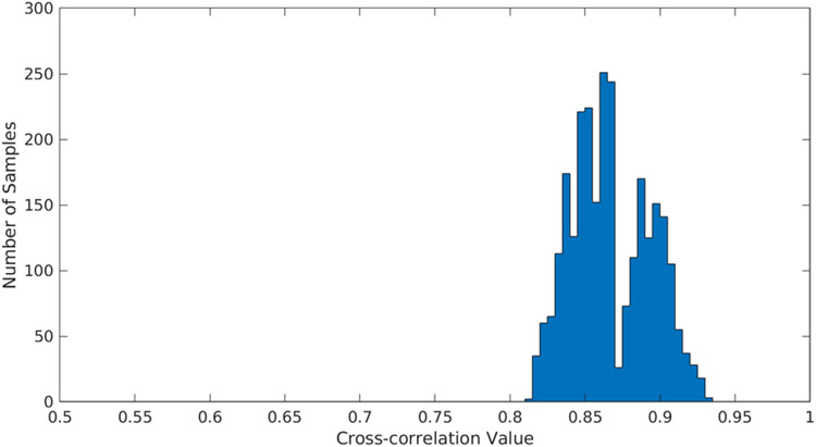
We show that combining ultrasound images into a 3D volume using our strategy produces cohesive registration results which build plausible scanned object surfaces. Additionally, the results of cross-correlation between frames in subsequent ultrasound swipes 2D scans resulted with the mean of 86.48% which indicates high procedure repeatability, even the worst case illustrated on the figure 8 figure number shows cross-correlation results over 80%.
Fig. 8.
Cross correlation results for 10 ultrasound swipes.
IV. CONCLUSIONS
This work evaluates the feasibility of repeatable robot-assisted thyroid ultrasound scanning. The work concerns a proofof-concept platform for automatic thyroid scanning using a research robotic manipulator. In this paper we described the motion planning strategy and its use for robot control for autonomous ultrasound data acquisition.
Finally, we conducted procedure reproducibility study for a static phantom subject. Repeatability is evaluated using frames within a single ultrasound scanning procedure designed for revisiting scanning regions multiple times. Image reproducibility was assessed using 2D cross-correlation method applied to the nearest neighboring ultrasound frames in the subsequent swipes. The collected experimental work presented supports the feasibility of automated medical ultrasound procedures.
ACKNOWLEDGEMENTS
Financial supports were provided in part by Worcester Polytechnic Institute Internal Foundation; in part by the National Institute of Health (DP5 OD028162). Authors do not declare conflict of interest.
REFERENCES
- [1].Pellegriti G, Frasca F, Regalbuto C, Squatrito S, and Vigneri R, “Worldwide increasing incidence of thyroid cancer: update on epidemiology and risk factors,” J. Cancer Epidemiol, vol. 2013, p. 965212, 2013, doi: 10.1155/2013/965212. [DOI] [PMC free article] [PubMed] [Google Scholar]
- [2].Ferrari SM, Fallahi P, Antonelli A, and Benvenga S, “Environmental Issues in Thyroid Diseases,” Front. Endocrinol, vol. 8, March 2017, doi: 10.3389/fendo.2017.00050. [DOI] [PMC free article] [PubMed] [Google Scholar]
- [3].Popoveniuc G and Jonklaas J, “Thyroid Nodules,” Med. Clin. North Am, vol. 96, no. 2, pp. 329–349, March 2012, doi: 10.1016/j.mcna.2012.02.002. [DOI] [PMC free article] [PubMed] [Google Scholar]
- [4].Fenster A, Parraga G, and Bax J, “Three-dimensional ultrasound scanning,” Interface Focus, vol. 1, no. 4, pp. 503–519, August 2011, doi: 10.1098/rsfs.2011.0019. [DOI] [PMC free article] [PubMed] [Google Scholar]
- [5].Huang Q and Zeng Z, “A Review on Real-Time 3D Ultrasound Imaging Technology,” BioMed Research International, 2017. [Online]. Available: https://new.hindawi.com/journals/bmri/2017/6027029/. [Accessed: 18-Dec-2019], [DOI] [PMC free article] [PubMed]
- [6].Ding M, Cardinal HN, and Fenster A, “Automatic needle segmentation in three-dimensional ultrasound images using two orthogonal two-dimensional image projections,” Med. Phys,vol. 30, no. 2, pp. 222–234, February 2003, doi: 10.1118/1.1538231. [DOI] [PubMed] [Google Scholar]
- [7].Ilunga-Mbuyamba E, Avina-Cervantes JG, Lindner D, Cruz-Aceves I, Arlt F, and Chalopin C, “Vascular Structure Identification in Intraoperative 3D Contrast-Enhanced Ultrasound Data,” Sensors, vol. 16, no. 4, April 2016, doi: 10.3390/s16040497. [DOI] [PMC free article] [PubMed] [Google Scholar]
- [8].Hacihaliloglu I, “3D Ultrasound for Orthopedic Interventions,” in Intelligent Orthopaedics: Artificial Intelligence and Smart Image-guided Technology for Orthopaedics, Zheng G, Tian W, and Zhuang X, Eds. Singapore: Springer, 2018, pp. 113–129. [Google Scholar]
- [9].Carter JL, Patel A, Hocum G, and Benninger B, “Thyroid gland visualization with 3D/4D ultrasound: integrated hands-on imaging in anatomical dissection laboratory,” Surg. Radiol. Anat, vol. 39, no. 5, pp. 567–572, May 2017, doi: 10.1007/s00276-016-1775-x. [DOI] [PMC free article] [PubMed] [Google Scholar]
- [10].Feinglass NG, Clendenen SR, Torp KD, Wang RD, Castello R, and Greengrass RA, “Real-time three-dimensional ultrasound for continuous popliteal blockade: a case report and image description,” Anesth. Analg, vol. 105, no. 1, pp. 272–274, July 2007, doi: 10.1213/01.ane.0000265439.02497.a7. [DOI] [PubMed] [Google Scholar]
- [11].Fang TY, Zhang HK, Finocchi R, Taylor RH, and Boctor E, “Force-assisted ultrasound imaging system through dual force sensing and admittance robot control,” Int. J. Comput. Assist. Radiol. Surg, pp. 1–9, March 2017, doi: 10.1007/s11548-017-1566-9. [DOI] [PubMed] [Google Scholar]
- [12].Hennersperger C et al. , “Towards MRI-Based Autonomous Robotic US Acquisitions: A First Feasibility Study,” IEEE Trans. Med. Imaging, vol. 36, no. 2, pp. 538–548, February 2017, doi: 10.1109/TMI.2016.2620723. [DOI] [PubMed] [Google Scholar]
- [13].Esteban J et al. , “Robotic ultrasound-guided facet joint insertion,” Int. J. Comput. Assist. Radiol. Surg. vol. 13, no. 6, pp. 895–904, June 2018, doi: 10.1007/s11548-018-1759-x. [DOI] [PubMed] [Google Scholar]
- [14].Zhang HK, Fang TY, Finocchi R, and Boctor EM, “High resolution three-dimensional robotic synthetic tracked aperture ultrasound imaging: feasibility study,” in Medical Imaging 2017: Ultrasonic Imaging and Tomography, 2017, vol. 10139, p. 1013914, doi: 10.1117/12.2254707. [DOI] [Google Scholar]
- [15].Zhang HK, Cheng A, Bottenus N, Guo X, Trahey GE, and Boctor EM, “Synthetic tracked aperture ultrasound imaging: design, simulation, and experimental evaluation,” J. Med. Imaging, vol. 3, no. 2, p. 027001, April 2016, doi: 10.1117/1.JMI.3.2.027001. [DOI] [PMC free article] [PubMed] [Google Scholar]
- [16].Bottenus N et al. , “Feasibility of Swept Synthetic Aperture Ultrasound Imaging,” IEEE Trans. Med. Imaging, vol. 35, no. 7, pp. 1676–1685, July 2016, doi: 10.1109/TMI.2016.2524992. [DOI] [PMC free article] [PubMed] [Google Scholar]
- [17].Besl PJ and McKay ND, “A Method for Registration of 3-D Shapes,” IEEE Trans Pattern Anal Mach Intell, 1992, doi: 10.1109/34.121791. [DOI] [Google Scholar]


