

Abstract
Graphitic multi‐walled carbon nanotubes (MWCNTs) can function as high‐performance cathode materials for rechargeable Al‐ion batteries with well‐defined discharging plateaus and reasonable charge/discharge C‐rates. However, the main intercalation/deintercalation or adsorption/desorption path of AlCl4 − anions into or onto G‐MWCNTs has not been elucidated. Herein, we used battery cells comprised of G‐MWCNTs with different aspect ratios, Al metal, and AlCl3/1‐ethyl‐3‐methylimidazolium chloride ionic liquid as the cathode, anode, and electrolyte, respectively. The electrochemical performance of the Al||G‐MWCNT cell increased as the aspect ratio of the G‐MWCNT cathode increased (i. e., longer and thinner). The degree of defects of the G‐MWCNTs was similar (0.15–0.22); hence, the results confirm that the main and alternate paths for the AlCl4 − intercalation/de‐intercalation or adsorption/desorption into/from or onto/from the G‐MWCNT are the basal and edge planes, respectively. The step‐like structures of defects on the basal plane provide the main reaction site for AlCl4 − anions.
Keywords: aluminum, aspect ratio, cathod materials, multi-walled carbon nanotubes, reaction mechanisms
A matter of ratios: During the charging process, it is proposed that the main pathway for the AlCl4 − intercalation or adsorption into/onto the MWCNT is the basal plane with defects, and the alternate pathway is the edge plane at both ends of the MWCNT. The thinner the MWCNT wall and the longer the length, the easier the intercalation/deintercalation and/or adsorption/desorption of AlCl4 −.

1. Introduction
Today, the global pursuit of sustainable energy systems aims to simultaneously reduce human dependence on fossil fuels and greenhouse gas emissions. These initiatives are based on strategies to develop more sustainable transportation systems such as electric vehicles and the ability to increase the consumption of renewable energy such as solar power and wind power technologies. However, given the intermittent nature of the production and consumption requirements of these renewable technologies, these initiatives require considerable electrical storage capabilities, which can only be expected to be effectively achieved with advanced batteries. Lithium‐ion batteries have received considerable attention for applications ranging from portable electronic devices to electric vehicles, because of their higher energy density compared to other rechargeable battery technologies.1, 2 However, lithium‐ion batteries are constrained because of the limited quantities of lithium element in the Earth's crust as well as safety issues. For the long‐term sustainable development of communities, it is urgent to develop efficient batteries using elements that are abundant and possess high safety.
Rechargeable aluminum batteries are particularly attractive since they can provide high specific capacity, safety, and cost‐effectiveness to fulfil future grid storage application demands. The high stability and low cost of aluminum, coupled with potential high theoretical specific capacities of 2978 mAh g−1 and 8034 mAh L−1,3 are tremendous advantages. Several Al‐ion batteries with various cathode materials have been reported.4, 5, 6, 7, 8 Among them, graphite materials are electrochemically stable in the AlCl3‐based ionic liquids that are commonly used as electrolytes for Al‐ion batteries. The Dai group7, 8 has demonstrated that Al‐ion batteries using 3D graphite foam as the cathode can provide a high charge/discharge current density with a long cycle life of up to 7500 cycles. Recently, Chen et al.9 reported that Al‐ion batteries with aerogel cathodes delivered a capacity of ∼100 mAh g−1 with a coulombic efficiency of ∼98 %. These studies have focused on 3D or 2D carbon materials such as graphite foam or graphene. However, few studies have explored the electrochemical performances of 1D carbon materials such as CNTs for use in Al‐ion batteries.10, 11, 12 Jiao et al.11 studied an aluminum‐ion asymmetric supercapacitor that utilized MWCNTs, aluminum metal, and aluminum chloride/1‐ethyl‐3‐methylimidazolium chloride (AlCl3/[EMIm]Cl) ionic liquid as the cathode, anode, and electrolyte, respectively. They proposed two types of energy storage mechanisms at low density: electrochemical double‐layer capacitance (adsorption/desorption of AlCl4 − on the surface of the tubular structure) and limited intercalation pseudocapacitance (intercalation/deintercalation of AlCl4 − within the tubular structure of the graphite layer). Zhang et al.12 reported the flexible unzipped MWCNTs (UCNT) as the positive electrode material of an aluminum battery with superior electrochemical performance. The Al/UCNT cell retained a specific capacity of ∼75 mAh g−1, even after 5500 charge/discharge cycles at 5000 mA g−1. However, both the Al/MWCNT11 and Al/UCNT12 cells exhibited capacitor behavior rather than battery behavior during charge/discharge. Very recently, our group13 reported that the Al‐based battery using graphitic MWCNT cathodes exhibited superior electrochemical performances, reasonable cyclic stability, and stable AlCl4 − intercalants in the space between the graphene layers of graphitic MWCNT (G‐MWCNT). However, the specific capacity and C‐rate capability of the graphitic MWCNT cathode were 40 % lower than those of graphene‐based (e. g., graphite foam) cathodes. Therefore, exploration of the reaction pathway of the AlCl4 − anion with G‐MWCNT has the potential to enhance the electrochemical performances of the Al‐MWCNT batteries.
In this study, we investigated Al||MWCNT cells using graphitic MWCNTs with different aspect ratios (length/outer diameter) as the cathode material. The degree of defects and crystallinity of the MWCNTs were first evaluated, then the electrochemical performances of the Al||MWCNT cells were examined. Finally, the most feasible reaction pathway between MWCNT and AlCl4 − was proposed.
2. Results and Discussion
SEM and TEM were performed on the four types of MWCNTs, and the results are shown in Figure 1. Figure 1a–d depict the SEM images of the four types of MWCNTs, respectively. The SEM images of the four types of MWCNTs displayed a typical elongated tubular microstructure. To further investigate the morphologies of the four types of MWCNTs, the thickness of the wall and outer diameter (OD) of the MWCNTs were studied using high‐resolution TEM. As shown in Figure 1e–h, the wall thicknesses of MWCNT 1–4 increased successively, measuring 3.2, 5.2, 12.3, and 25.6 nm, respectively. Therefore, the ODs and wall thicknesses of the MWCNTs measured by HRTEM were consistent with the specifications provided by XFNANO. Figures 1e–h revealed that the surface of the basal plane of the MWCNTs was bumpy in some places, which may be attributed to the defects (displacement of graphitic layers) in the MWCNTs. These defects might provide the intercalation/deintercalation pathway of AlCl4 − into/from those MWCNTs and will be discussed in the subsequent section. A schematic representation of the wall thickness and length of the four MWCNTs is shown in Figure 1i. As shown in Figures 1e–h, the diameter of MWCNT‐1 was the lowest (i. e., highest aspect ratio) and that of MWCNT‐4 was the greatest (i. e., lowest aspect ratio).
Figure 1.

(a–d) Scanning electron microscopy images, (e–h) High‐resolution transmission electron microscopy images and (i) schematic drawing of the four types of MWCNTs with different aspect ratios.
The degree of defects and crystallinity of MWCNTs were studied by Raman spectroscopy (Figure 2a) and X‐ray diffraction (Figure 2b), respectively. Figure 2a shows the Raman spectra of the MWCNT samples. The Raman spectra of carbon materials can be divided into first‐ and second‐order regions.14 The first‐order region of the Raman spectra is 1100–1800 cm−1.14 For perfect carbon materials, only one peak of the G band appears in the first‐order region. For less well‐ordered carbon materials, an additional band can be found in the first‐order region at ∼1350 cm−1, commonly called the defect band or D band.15, 16 The ratio of the peak height of the D and G bands, R=(ID/IG), represents the degree of graphitization of the carbon material. As shown in Figure 2a, the values of R (ID/IG) of the MWCNT samples range from 0.15–0.22, thus suggesting that the MWCNTs were well‐graphitized and the defect contents were similar. In the second‐order region (1800–3000 cm−1), the main band at ∼2700 cm−1 is called 2D.17, 18 Figure 2a shows that the intensity of the 2D‐band of MWCNT‐1 was the lowest and MWCNT‐4 was the highest. These observations indicate that the smallest and largest diameter was present in MWCNT‐1 and MWCNT‐4,19 respectively. There are several studies reported the dependence of I2D/ID ratio on the diameter of MWCNT,19, 20, 21 the rise of the I2D/ID ratio indicates the increase of diameter. The I2D/ID ratio of MWCNT‐1 and MWCNT‐4 is 4.40 and 5.91, respectively, suggesting the diameter of MWCNT‐4 is larger than that of MWCNT‐1, which correlates with the results obtained from the TEM characterization of the MWCNTs (Figure 1e and h). The crystallinity of the MWCNTs could be determined by the shape and height of the corresponding diffraction peaks of the XRD spectra. Figure 2b shows that the diffraction peaks of the MWCNTs display at ∼26° and 44°, which correspond to the typical (002) and (100) planes of graphitic materials, respectively.13 The XRD spectra in Figure 2b reveal diffraction peaks of MWCNT‐1, MWCNT‐2 and MWCNT‐3 that were sharp and intense, thus indicating a high degree of crystallinity. However, MWCNT‐4 exhibited lower crystallinity than the other three MWCNTs, which was characterized by the broadened (002) peak (see Figure 2b). Noticeably, no impurity peak was observed, indicating the high quality of the MWCNTs.
Figure 2.

(a) Raman spectra and (b) XRD spectra of the four types of MWCNT.
Figure 3a shows the galvanostatic charge/discharge curves of the MWCNTs as cathodes using AlCl3/[EMIm]Cl (1.3 mole ratio) electrolyte, where Al was used as the anode. Well‐defined discharging voltage plateaus (2.25–1.75 V) were observed for all the Al|AlCl3‐[EMIm]Cl|MWCNT cells (Al||MWCNT cell). Al/MWCNT‐1 exhibited the highest specific capacity of 65 mAh g−1 of all the Al||MWCNT cells with ∼100 % Coulombic efficiency at a current density of 200 mA g−1. Although the discharge plateaus of the Al||MWCNT‐2, Al||MWCNT‐3 and Al||MWCNT‐4 cells were noticeable, nevertheless, the charge/discharge capacity decreased. MWCNT‐1 cathode material had the highest aspect ratio among the MWCNTs and displayed the best electrochemical performance, suggesting that the electrochemical performance of the Al||MWCNT cells was dependent on the length of the basal plane (i. e., high aspect ratio) of the MWCNTs. MWCNTs with adjustable length or diameter (e. g., a fixed length and different diameters) will be interesting cathodes to study. Figure 3b shows the charge and discharge capacities and the corresponding Coulombic efficiencies of the Al||MWCNT‐1 cell at different current densities. At current densities of 200 mA g−1, 300 mA g−1, 500 mA g−1, 1 A g−1, 2 A g−1, and 5 A g−1, the discharge capacities of the cells gradually decreased as the current density increased. Notably, as the current density was reduced, the discharge capacities of the cell gradually increased again, thus indicating a high reversibility of the cell. Accordingly, the Al||MWCNT‐1 cell shows a favorable C‐rate capability, i. e., low capacity decay while current density was increased from 200 to 2000 mA g−1 (Figure 3b). However, the specific capacity delivered from the Al||MWCNT‐1 cell (∼65 mAh g−1) is relatively lower than that of Al||graphite cell (∼110 mAh g−1)22 and Al||graphene cell (∼100 mAh g−1),9 which could be further increased and is discussed in the following section.
Figure 3.

(a) Charge/discharge curves of four types of MWCNT cathodes at 200 mA g−1 current density. (b) Capacity retention of the Al||MWCNT‐1 cell charge/discharge cycled at various current densities.
Both the battery and the capacitor materials include two types of electrochemical energy storage: 1) pseudocapacitance characteristics at the interface of the electrode materials, and 2) diffusion‐controlled battery behavior in the bulk of the electrode material (typical traditional battery characteristics).23 Pseudopotential behavior at the interface of electrode materials can result in improved power characteristics, whereas diffusion‐controlled battery behavior in the bulk of the electrode material (typical traditional battery characteristics) can produce enhanced energy characteristics.23 Therefore, the battery behaviors and/or pseudo‐capacitive behaviors of the MWCNTs used as cathode materials for the Al/MWCNT cell for AlCl4 − storage were investigated using cyclic voltammetry (CV) measurements at different scan rates (1–20 mV s−1). As shown in Figure S1, all the CV curves of the Al/MWCNT cells exhibit four couples of typical redox peaks (C1, C2, C3, and C4). This is similar to the previous results obtained from the electrochemical analysis of AlCl4 − intercalation/deintercalation into/from the graphite or graphene electrodes.24, 25, 26 Typically, the CV curves display four couples of visible cathodic and anodic peaks (C1 to C4), which indicate the reversible intercalation/deintercalation of AlCl4 − in graphite due to the stage transformations among the AlCl4 −‐graphite intercalation compounds.25 Figure 4 represents a plot of log(i) versus log(v) from 1–20 mV s−1 for cathodic peaks. Assuming that the cathodic peak current obeys a power‐law relationship with the scan rate leads to:27, 28, 29

Figure 4.

b‐value determination of the cathodic peak currents of (a) Al||MWCNT‐1, (b) Al||MWCNT‐2, (c) Al||MWCNT‐3, and (d) Al||MWCNT‐4 cells. Insets: the ratio between battery behavior (blue dotted rectangle) and capacitive behaviors (red solid rectangle) at different scan rates of the Al||MWCNT cells.
where a and b are adjustable values. The slope of the linear line in Figure 4b corresponds to the b‐value. Generally, the b‐value is between 0.5 and 1.0. When the b‐value is close to 0.5, the energy storage method of the electrode material is mainly the linear diffusion‐controlled battery behavior; a b‐value of 1 suggests that the current is surface‐controlled (i. e., capacitive behavior).27 Taking the Al||MWCNT‐1 cell as an example, the b‐values of C1, C2, C3, and C4 were calculated as 0.465, 0.540, 0.504, and 0.521, respectively, indicating that the kinetics is mainly diffusion‐controlled (Figure 4b). Furthermore, in order to quantitatively separate the contribution of surface‐limited capacitive and diffusion‐controlled intercalation elements, the method proposed by the Dunn group27, 29 was applied, which was based on the dependence between the peak currents and the scan rates:

where, i represents the total current, k 1 and k 2 are constants, and k 1 v and k 2 v 1/2 represent the current generated by the surface capacitance and the current generated by the AlCl4 − intercalation in the MWCNT cathodes, respectively. As shown in the inset of Figure 4, the blue dotted rectangle represents the battery behavior (AlCl4 − intercalation characteristics) and the red solid rectangle represents the pseudo‐capacitance behavior.28, 30 For the Al||MWCNT‐1 and Al||MWCNT‐2 cells, the battery behavior dominates at scan rates of 1–20 mV s−1 for the C1, C2, C3, and C4 peaks in the inset of Figure 4a and b. As shown in the inset of Figures 4c and d, the battery behavior for the Al||MWCNT‐3 and Al||MWCNT‐4 cells dominates at scan rates of 1–2 mV s−1 for C1 and C2 peaks, and the battery behavior is weakened with the increase in the scan rate and mainly showed pseudo‐capacitive behavior at scan rates of 10 mV s−1 and 20 mV s−1. These results (Figure 4) correlate with the galvanostatic charge/discharge data (Figure 3a), where the Al||MWCNT‐1 cell (dominated by battery behavior) exhibited the highest specific capacity among the Al||MWNCT cells.
The relationship between the aspect ratio (length of basal plane /OD MWCNT) and specific capacities of the Al||MWCNT cells was summarized (adopting data from Figures 2 and 3) and shown in Figure 5. The average ODs for MWCNT‐1, MWCNT‐2, MWCNT‐3, and MWCNT‐4 were ∼11.5, ∼15, ∼25, and ∼50 nm, respectively. The average lengths were 30, 17.5, 17.5, and 15 μm for MWCNT‐1, MWCNT‐2, MWCNT‐3, and MWCNT‐4, respectively. The specific capacity of the battery achieved values of 65, 32, 22, and 10 mAh g−1. In addition, the BET surface area of MWCNT‐1 (∼100 m2 g−1) was ∼25 m2 g−1 higher than that of MWCNT‐4 (∼75 m2 g−1). The larger the specific surface area of the MWCNT, the more favorable it is for AlCl4 − intercalation/de‐intercalation and/or adsorption/de‐adsorption, thus resulting in higher specific capacity. These comparisons confirmed that the specific capacity of the Al||MWCNT cell is dominated by the aspect ratio of the MWCNT cathode material.
Figure 5.

Relationship between various MWCNT cathodes with different aspect ratios and the corresponding specific capacities of the Al||MWCNT cells.
Figure 6 shows a schematic representation of the interaction between graphitic MWCNT and AlCl4 − based on the experimental results discussed above. Experimental results demonstrated that MWCNT‐1 with the longest length and the thinnest wall (i. e., high aspect ratio) exhibited the highest specific capacity (65 mAh g−1), whereas the MWCNT‐4 with the shortest length and the thickest wall (i. e., low aspect ratio) showed the lowest specific capacity (10 mAh g−1). This indicates that the thinner the MWCNT wall and the longer the length, the easier the intercalation/deintercalation and/or adsorption/desorption of AlCl4 −. In addition, the HR‐TEM morphology revealed that the surfaces of the MWCNTs were bumpy, which may be attributed to the surface defects. The typical surface defects in MWCNTs are caused by the displacement of graphite layers. Based on the previous study, there are more ‘‘active sites’’ at the edges of broken graphite structures in MWCNTs with defects,17, 25, 26 which facilitated the stable intercalation or adsorption of the AlCl4 − during the charging process. Here, during the charging process, it is proposed that the main pathway for the AlCl4 − intercalation or adsorption into/onto the MWCNT is the basal plane with defects, and the alternate pathway is the edge plane at both ends of the MWCNT.
Figure 6.
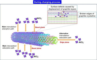
Schematic representation of the possible mechanisms of interfacial interaction between AlCl4 − and graphitic MWCNTs.
In the previous study, Chen et al.9 proposed that defects (sp3 carbons and oxygen‐containing groups) hindered the intercalation/deintercalation reactions between layered graphene and AlCl4 −, which led to the decreased specific capacity of Al‐based battery using few‐layer graphene aerogel as the cathode material. Therefore, it would be necessary to define and discuss the defects of carbon materials, whether they enhance or reduce the electrochemical performance (particularly, the specific capacity). Defects could be generated with various characteristics such as edges, vacancies, boundaries, implanted atoms as well as defects in graphitic sp2 and amorphous sp3 carbon hybridization.31 For providing reaction paths, defects such as edges, vacancies and boundaries are preferable, as these sites were the positions where the AlCl4 − intercalated/deintercalated into/from graphitic MWCNT (Figure 6). The implanted atoms (e. g., oxygen‐containing groups) and amorphous sp3 carbons occupied the active site of carbon, which decreased the active space for the AlCl4 − intercalant.9 However, the effect of these implanted atoms and amorphous sp3 carbons on the stability of layered graphene has not been discussed,9 which is also an interesting topic for graphitic MWCNTs.
3. Conclusion
Graphitic MWCNT cathodes with similar degrees of defects but different aspect ratios were studied. Both MWCNTs exhibited well‐defined hollow tubular structures and good graphitic structure/orientation, which were confirmed by the analytical methods of SEM, TEM, XRD, and Raman spectra. Electrochemical performances, in terms of specific capacity and working voltage, of the Al||MWCNT battery were increased by increasing the aspect ratio of the MWCNT cathode (i. e., longer and thinner). In addition, the electrochemical process of MWCNT cathodes with high aspect ratio was dominated by intercalation/deintercalation (battery) behavior rather than adsorption/de‐adsorption (capacitor) behavior. Together with the material characterization and electrochemical performance of the MWCNT cathode, we proposed a possible mechanism in which the main and alternate pathways for the AlCl4 − intercalated into or adsorbed onto the MWCNTs are the basal and edge planes, respectively. In the future, the electrochemical performance of MWCNT cathodes, such as the specific capacity and C‐rate capability, might be further enhanced by enlarging the degree of defects (e. g., vacancies and boundaries) on the basal plane of the MWCNT.
Experimental Section
MWCNTs
For the cathode materials, graphitic MWCNTs purchased from Nanjing XFNANO Technology Co., Ltd (XFNANO) were labeled as MWCNT‐1 (outer diameter (OD): 8–15 nm, length: 10–50 μm); MWCNT‐2 (OD: 10–20 nm, length: 5–30 μm); MWCNT‐3 (OD: 20–30 nm, length: 5–30 μm); MWCNT‐4 (OD: >50 nm, length: 5–20 μm). The above specifications were provided by XFNANO; however, we examined the thickness of the wall and OD of the MWCNTs to confirm the exact size. The average values of the length of MWCNTs were used directly from the specifications as they correlated with our observations.
Characterization of MWCNTs
The microstructures of the MWCNTs were determined using TEM (FEI Tecnai G2 F20, America) and SEM (Apreo S HiVac, Japan). Raman spectroscopy (Horiba Jobin Yvon, France, with a 532‐nm YAG laser) was used to characterize the graphitic structure of the MWCNT samples. X‐ray diffraction (XRD) was performed using Cu Kα radiation (λ=1.54056 Å) on a D8 X‐ray diffractometer (Bruker, Germany).
Fabrication of Al/MWCNT Cells
Aluminum foil (0.2 mm thickness, 99.99 % purity) and nickel foil (0.2 mm thickness, 99.0 % purity) were received from the General Research Institute for Nonferrous Metals (Beijing, P.R. China). The Al foil was polished using sandpaper and cleaned with an ethanol solution in an ultrasonic bath. Then, the Al foil was dried and used as the anode. Ultrapure water (18.2 MΩ cm−1), 80 wt.% MWCNTs, and 20 wt.% LA132 polyacrylic latex binder (Chengdu Institute of Organic Chemistry, China) were mixed together and then stirred for 4 h, forming a uniform slurry with a viscosity of ∼1400 cP. The slurry was pasted onto a Ni foil current collector, dried at 80 °C for 12 h under vacuum conditions, and was used as the cathode in the pouch cell. Loading of the MWCNTs was 1–3 mg cm−2. The cathode and anode sizes were 90 mm2. The electrolyte used for the Al||MWCNT cells was a mixture of AlCl3 and [EMIm]Cl in a 1.3 : 1 mole ratio. Glass fiber was used as the separator. The electrolyte (∼1.0 mL) was injected with a disposable injector and the pouch cells were sealed using a hot sealer.
Electrochemical Measurements
The galvanostatic charge/discharge measurements of the Al||MWCNT cells were conducted within a voltage range of 1.0–2.45 V using a NEWARE CT‐4008‐5V1A‐S1 battery test system (Neware, Shenzhen, China). The specific capacity was calculated based on the mass of the MWCNT on the cathode. Cyclic voltammetry (CV) measurements were conducted at different scan rates over a 1.5–2.45 V range using a VMP3 potentiostat/galvanostat (Biologic Science Instrument, France). In the CV test, MWCNT was used as the working electrode, and the Al foil was simultaneously used as the counter and reference electrodes.
The electrochemical workstation VMP3 was also used to measure the electrochemical impedance of the Al||MWCNT cells. Electrochemical impedance spectroscopy (EIS) uses a small amplitude sinusoidal waveform as the disturbance signal for the measurement, which has the advantages of a short test time, minimal interference, and reliable results. The test frequency scope ranged from 100 mHz–100 kHz, and the tests were performed under an open‐circuit voltage.
Conflict of interest
The authors declare no conflict of interest.
Supporting information
As a service to our authors and readers, this journal provides supporting information supplied by the authors. Such materials are peer reviewed and may be re‐organized for online delivery, but are not copy‐edited or typeset. Technical support issues arising from supporting information (other than missing files) should be addressed to the authors.
Supplementary
Acknowledgements
The authors acknowledge financial support from the Qingdao Scientific and Technological Innovation High‐level Talents project: Aluminum‐ion power and energy storage battery (No. 17‐2‐1‐1‐zhc), the Taishan Scholar Project of Shandong Province, China (No. tsqn20161025), and the Qingdao Entrepreneurial Innovation Leaders Plan (No. 16‐8‐3‐1‐zhc).
L. Hou, H. Cao, M. Han, Z. Lv, S. Zhou, H. Chen, H. Du, M. Cai, Y. Zhou, C. Meng, Y. Bian, M.-C. Lin, ChemistryOpen 2020, 9, 812.
Contributor Information
Prof. Yinghui Bian, Email: yinghuibian@sdust.edu.cn.
Prof. Meng‐Chang Lin, Email: mengchanglin@sdust.edu.cn.
References
- 1. Hong X., Mei J., Wen L., Tong Y., Vasileff A. J., Wang L., Liang J., Sun Z., Dou S. X., Adv. Mater. 2019, 31, 1802822–1802831. [DOI] [PubMed] [Google Scholar]
- 2. Yan Y. Y., Cheng C., Zhang L., Li Y. G., Lu J., Adv. Energy Mater. 2019, 9, 1900148–1900162. [Google Scholar]
- 3. Gao T., Li X., Wang X., Hu J., Han F., Fan X., Suo L., Pearse A. J., Lee S. B., Rubloff G. W., Gaskell K. J., Noked M., Wang C., Angew. Chem. Int. Ed. 2016, 55, 9898–9901; [DOI] [PubMed] [Google Scholar]; Angew. Chem. 2016, 128, 10052–10055. [Google Scholar]
- 4. Geng L., Lv G., Xing X., Guo J., Chem. Mater. 2015, 27, 4926–4929. [Google Scholar]
- 5. Bian Y., Li Y., Yu Z., Chen H., Du K., Qiu C., Zhang G., Lv Z., Lin M.-C., ChemElectroChem 2018, 5, 3607–3611. [Google Scholar]
- 6. Hudak N. S., J. Phys. Chem. C 2014, 118, 5203–5215. [Google Scholar]
- 7. Lin M.-C., Gong M., Lu B., Wu Y., Wang D. Y., Guan M., Angell M., Chen C., Yang J., Hwang B. J., Dai H., Nature 2015, 520, 325–328. [DOI] [PubMed] [Google Scholar]
- 8. Wu Y., Gong M., Lin M. C., Yuan C., Angell M., Huang L., Wang D. Y., Zhang X., Yang J., Hwang B. J., Dai H., Adv. Mater. 2016, 28, 9218–9222. [DOI] [PubMed] [Google Scholar]
- 9. Chen H., Guo F., Liu Y., Huang T., Zheng B., Ananth N., Xu Z., Gao W., Gao C., Adv. Mater. 2017, 29, 1605958. [DOI] [PubMed] [Google Scholar]
- 10. Bhauriyal P., Mahata A., Pathak B., Chem. – An Asian J. 2017, 12, 1944–1951. [DOI] [PubMed] [Google Scholar]
- 11. Jiao H., Wang J., Tu J., Lei H., Jiao S., Energy Technol. 2016, 4, 1112–1118. [Google Scholar]
- 12. Zhang E., Wang J., Wang B., Yu X., Yang H., Lu B., Energy Storage Mater. 2019, 23, 72–78. [Google Scholar]
- 13. Han M., Lv Z., Hou L., Zhou S., Cao H., Chen H., Zhou Y., Meng C., Du H., Cai M., Bian Y., Lin M.-C., J. Power Sources 2020, 451, 227769. [Google Scholar]
- 14. Vázquez-Santos M. B., Geissler E., László K., Rouzaud J. N., Martínez-Alonso A., Tascón J. M. D., J. Phys. Chem. C 2012, 116, 257–268. [Google Scholar]
- 15. Dresselhaus M. S., Jorio A., Hofmann M., Dresselhaus G., Saito R., Nano Lett. 2010, 10, 751–758. [DOI] [PubMed] [Google Scholar]
- 16. Kawashima Y., Katagiri G., Phys. Rev. B 1995, 52, 10053–10059. [DOI] [PubMed] [Google Scholar]
- 17. Centi G., Perathoner S., ChemSusChem 2011, 4, 913–925. [DOI] [PubMed] [Google Scholar]
- 18. Dresselhaus M. S., Dresselhaus G., Saito R., Jorio A., Phys. Rep. 2005, 409, 47–99. [Google Scholar]
- 19. Kuznetsov V. L., Bokova-Sirosh S. N., Moseenkov S. I., Ishchenko A. V., Krasnikov D. V., Kazakova M. A., Romanenko A. I., Tkachev E. N., Obraztsova E. D., Phys. Status Solidi B 2014, 251, 2444–2450. [Google Scholar]
- 20. Singh D. K., Iyer P. K., Giri P. K., Diamond Relat. Mater. 2010, 19, 1281–1288. [Google Scholar]
- 21. Antunes E. F., Lobo A. O., Corat E. J., Trava Airoldi V. J., Carbon 2007, 45, 913–921. [Google Scholar]
- 22. Wang D.-Y., Wei C.-Y., Lin M.-C., Pan C.-J., Chou H.-L., Chen H.-A., Gong M., Wu Y., Yuan C., Angell M., Chen Y.-J., Wen C.-Y., Chen C.-W., Hwang B.-J., Chen C.-C., Dai H., Nat. Commun. 2017, 8,14283–14289. [DOI] [PMC free article] [PubMed] [Google Scholar]
- 23. Li Z., Li J., Kang F., Electrochim. Acta 2019, 298, 288–296. [Google Scholar]
- 24. Elia G. A., Kyeremateng N. A., Marquardt K., Hahn R., Batter. Supercaps 2018, 2, 83–90. [Google Scholar]
- 25. Pan C.-J., Yuan C., Zhu G., Zhang Q., Huang C.-J., Lin M.-C., Angell M., Hwang B.-J., Kaghazchi P., Dai H., Proc. Natl. Acad. Sci. USA 2018, 115, 5670–5675. [DOI] [PMC free article] [PubMed] [Google Scholar]
- 26. Chen H., Xu H., Wang S., Huang T., Xi J., Cai S., Guo F., Xu Z., Gao W., Gao C., Sci. Adv. 2017, 3, 7233. [DOI] [PMC free article] [PubMed] [Google Scholar]
- 27. Brezesinski T., Wang J., Tolbert S. H., Dunn B., Nat. Mater. 2010, 9, 146–151. [DOI] [PubMed] [Google Scholar]
- 28. Kim H., Hong J., Park Y. U., Kim J., Hwang I., Kang K., Adv. Funct. Mater. 2015, 25, 534–541. [Google Scholar]
- 29. Wang J., Polleux J., Lim J., Dunn B., J. Phys. Chem. C 2007, 111, 14925–14931. [Google Scholar]
- 30. Li Z., Liu J., Niu B., Li J., Kang F., Small 2018, 14, 1800745. [DOI] [PubMed] [Google Scholar]
- 31.R. Das, in NANOHYBRID Catal. BASED CARBON Nanotub. A STEP-BY-STEP Guidel. FROM Prep. TO Demonstr, 2017.
Associated Data
This section collects any data citations, data availability statements, or supplementary materials included in this article.
Supplementary Materials
As a service to our authors and readers, this journal provides supporting information supplied by the authors. Such materials are peer reviewed and may be re‐organized for online delivery, but are not copy‐edited or typeset. Technical support issues arising from supporting information (other than missing files) should be addressed to the authors.
Supplementary