

Abstract
The Gamma Knife® Icon™ CBCT facilitates frameless radiosurgery. In the vendor-recommended workflow, MRI is co-registered directly to CBCT for planning. Alternatively, MRI is co-registered to a diagnostic CT, which is then co-registered to CBCT. Our objective is to evaluate if this additional CT is necessary for more accurate registrations. Nine small spherical targets were generated onto 14 patient data-sets. Single-shot treatment plans were created. Geometric and dosimetric differences between the two workflows were determined. Mean target displacement was 0.5±0.3mm; average PTV coverage loss was 4.3±5.0%. For 19 clinical targets in 14 patients, the mean displacement and coverage change was 0.6±0.4mm and 1.3±1.6%. Eleven surrogate landmarks were contoured on a phantom MRI and registered to the CBCT using both workflows. The registration uncertainty was 0.50±0.65mm and 0.32±0.47mm for the MRI-CT-CBCT and MRI-CBCT respectively. As neither workflow was significantly more accurate, the additional CT is unnecessary for most cases.
Keywords: Gamma Knife Icon, co-registration, CBCT, frameless radiosurgery, fractionated radiosurgery
Introduction
Classic Leksell Gamma Knife® (GK) (Elekta Instrument AB, Stockholm, Sweden) systems utilize a rigid frame fixed to the patient skull to define the frame of reference for stereotactic space, and to immobilize the patient’s skull relative to the treatment unit.1 The GK Icon™ system facilitates frameless treatments by using a thermoplastic mask for immobilization and an onboard cone-beam computed tomography (CBCT) imaging system to define stereotactic space.2–4 In the vendor-recommended workflow for frameless treatment, a magnetic resonance image (MRI) for target, organ at risk (OAR), and surface definition and a CBCT for stereotactic space definition are acquired prior to treatment planning.5 The MRI is co-registered to the CBCT using Leksell GammaPlan’s (LGP) built-in co-registration algorithm.6, 7 However, due to the limited soft tissue contrast in GK CBCT images, the MRI and CBCT images likely share limited mutual information. An alternate workflow is proposed in which a diagnostic CT is acquired prior to treatment planning and is included in the registration workflow. The MRI is co-registered to the diagnostic CT, and the diagnostic CT is then in turn co-registered to the CBCT. The CT shares mutual information with both the MRI and CBCT. Grey and white matter contrast, ventricles, optic nerves etc are visible in the MRI and diagnostic CT; bony structures are well-defined in the CBCT and the diagnostic CT. This alternate workflow is routinely practiced at some institutions.3, 8, 9
Chung et al. have shown on the GK Icon™ system that the registration between CT and CBCT images in an anthropomorphic phantom result in a mean deviation of 0.5 ± 0.2 mm and the registration of 41 patient MRI to CBCT images results in a larger mean deviation of 0.8 ± 0.3 mm, but did not address the three image co-registration chain (MRI to CT to CBCT).10 In an MRI distortion head phantom, the positions of 20 landmarks were measured 3 times each in a CT and an MRI each registered to the CBCT to assess the CT to CBCT and MRI to CBCT co-registrations. The deviation for CT to CBCT co-registration was 0.2 ± 0.1 mm; the co-registration deviation was larger for MRI to CBCT (0.4 ± 0.2 mm).11 An Elekta White Paper found target registration errors registering MR to CBCT to be 0.31-0.54 mm and 0.16-0.26 mm for MRI-CT for all intracranial locations for five patients.12 Ruschin et al. investigated the variability of MRI to CT, CT to CBCT, and MRI to CBCT co-registration for 15 patients on the GK Icon™, finding that all co-registration workflows were repeatable with repeatability less than 0.2mm.9 That study also looked at the difference between MRI to CBCT co-registration and MRI to CT to CBCT co-registration and reported a mean compound registration error of 0.44 mm, with a maximum value of 0.31-0.9 mm within the central 16 cm of the MRI scan.9 The analysis was performed on individual image voxels, not on target structures so the clinical significance of the reported compound registration error is unclear. Additionally, the magnitude of the dosimetric effects caused by these registration uncertainties have not been reported.
In this study, the accuracy of the two co-registration workflows and the resulting dosimetric effects are compared using the images of 14 patients for two experiments and phantom images for a third. In the first experiment, plans were created for the same set of nine artificial, small spherical volumes in 14 patient images. In the second experiment, plans were created for 19 clinical target volumes in the same 14 patients. Finally, a phantom study with 11 surrogate target structures was performed to determine which registration workflow was more accurate. In all experiments, changes in target/structure location and/or target coverage due to changing image registration workflows are reported.
Materials and Methods
All patients received CBCT, diagnostic CT, and MRI scans as part of their treatment planning. Stereotactic CBCT scans on the GK Icon system were acquired with the following parameters: 90kVp, 0.5mm uniform 3D resolution Diagnostic CT scans were obtained with the following parameters: helical CT on GE Discovery CT750HD: 120kVp, 1.25mm slice thickness, 0.5mm in-plane resolution The MRI images were acquired on a Philips 3T Achieva scanner with a dedicated post-contrast 3D T1 protocol for GK SRS patients. Scans had 1mm slice thickness, 0.75-1mm in-plane resolution, 270 x 270 x 200 mm field of view, 216.6 Hz/pixel bandwidth, and an automatic non-linear distortion correction algorithm was used. Institutional review board approval was obtained for the use of patient data in this retrospective study.
Multiple Spherical Targets
A set of eight 8 mm diameter and an additional 0.28 mm diameter spherical volumes were created and copied onto the MRI for 14 patients to simulate metastatic brain lesion targets (targets 1-8, volume 0.27cm3) and a trigeminal neuralgia target volume (target 9, volume 0.01cm3). Targets were created using the “draw sphere” function in iPLAN RT Image 4.1 (BrainLAB AG, Munich Germany) and then transferred to LGP. This function allowed for the creation of spherical targets with specific diameters. One patient’s MRI field of view (FOV) did not encompass the entire skull volume so only five targets were included for that patient. Target locations were selected to encompass the full cranial extent and represent typical intracranial locations: brainstem, left cerebellopontine angle (CPA), left posterior cerebellum, left lateral temporal lobe, left frontal lobe, left parietal lobe, left parasagittal sinus, thalamus, and left trigeminal nerve (Figure 1).
Figure 1.

Eight 8 mm diameter volumes (targets 1-8) were drawn throughout the brain to represent typical intracranial treatment locations. A single 0.28 mm diameter volume (target 9) was drawn on the left trigeminal nerve.
The MRI was co-registered to the CT using the entire skull as a volume of interest (VOI). The registration was reviewed by examining the alignment of the skull, ventricles, grey/white matter contrast, optic nerves etc. in axial, sagittal, and coronal views. The CT was then co-registered to the CBCT using the same VOI and the bone alignment was evaluated. All registrations were determined to be clinically acceptable. The coordinates of the center of each target, as identified by the LGP software, were recorded. The plans consisted of a single shot placed at the center of each target. For targets 1-8, all sectors were set to 8 mm collimators; for target 9, all sectors were set to 4 mm. The shot position was chosen to provide 100% target coverage while prescribing to the highest possible isodose line (IDL), ensuring the most conformal single-shot plan. For targets 1-8, dose was prescribed to the 62-83% IDL, and for target 9, prescription IDLs ranged from 76-92%. Shot locations and prescription IDL were recorded.
To change the image co-registration workflow, a new examination was created for each patient; the MRI and CBCT were imported and co-registered. The alignment of globes in both images and of bone in the CBCT with the low-signal areas in the MRI were evaluated. All registrations were determined to be clinically acceptable. The treatment plans were copied by placing shots at the same LGP coordinates and prescribing to the same IDL as in the original plan. The new coordinates of the center of each target and the target coverage were recorded. A 3D target displacement was found by adding the differences in the three target coordinates in quadrature. The decrease in coverage was found by subtracting the target coverage in the CBCT-MRI registration plan from the original plan (100%). Due to the study design of the original plan coverage set to 100%, target coverage can only decrease in this experiment. It should be noted that since neither workflow is known to be produce the ground truth location of the target in stereotactic coordinates, the coverage decrease was interpreted as a change in target coverage.
Patient-Specific Targets
For the same 14 patients, the clinical treatment plans were created using the MRI to CT to CBCT registration workflow. A total of 19 lesions with volumes ranging from 0.003-5.3 cm3 were treated. Twelve of 19 lesions had a 1 mm expansion of the GTV to create a PTV as is our typical clinical practice for frameless GK treatments; in the remaining seven lesions, the PTV was taken to be the GTV with no expansion. The PTV sizes ranged from 0.003-7.7 cm3. Plans were created for prescription doses of 12-25Gy in 1-5 fractions, and ranged from 1-18 shots and from 45-88% prescription IDL (Table 1). Target center locations and coverage parameters were recorded. To alter the co-registration workflow, the “replan” function in the LGP software was used to retain the stereotactic reference information in the CBCTs so the target and shot locations remained the same relative to the CBCT anatomy. The MRI and structures were re-imported so the contours remained in the same locations relative to the MRI image. The MRIs were co-registered to the CBCTs in the replan examinations; the registrations were reviewed, and determined to be clinically acceptable. Clinical plans were copied by placing the shots at the same LGP coordinates and prescribing to the same IDL as in the original plan. The new PTV target center locations and GTV and PTV coverage parameters were recorded.3D target displacements and coverage changes were calculated from the differences between the two workflows.
Table 1.
Target and planning characteristics for 19 targets in 14 patients.
| Patient | GTV Volume (cm3)† | PTV Volume (cm3) | # shots | Total Dose (Gy) | # Fractions | GTV Coverage | PTV Coverage | Selectivity | GI | % IDL Prescribed |
| 1 | 0.65 | 1.12 | 2 | 15 | 1 | 1 | 1 | 0.74 | 3.01 | 88 |
| 1 | 0.43 | 0.72 | 3 | 15 | 1 | 1 | 1 | 0.73 | 4.01 | 88 |
| 2 | 0.82 | 1.65 | 14 | 12 | 1 | 1 | 0.949 | 0.45 | 2.81 | 45 |
| 3 | 1.30 | 2.27 | 14 | 25 | 5 | 1 | 0.99 | 0.71 | 2.66 | 45 |
| 4 | 1.17 | 1.50 | 11 | 25 | 5 | 1 | 0.98 | 0.82 | 2.95 | 46 |
| 5 | 1.83 | 3.09 | 11 | 12 | 1 | 1 | 0.99 | 0.8 | 2.67 | 47 |
| 6 | 0.84 | 1.63 | 13 | 12 | 1 | 1 | 0.99 | 0.83 | 2.71 | 50 |
| 7 | 0.19 | 0.43 | 1 | 15 | 1 | 1 | 0.87 | 0.65 | 3.27 | 50 |
| 8 | 1.44 | 2.31 | 11 | 12 | 1 | 1 | 0.99 | 0.74 | 2.91 | 54 |
| 9 | - | 2.24 | 13 | 18 | 1 | - | 0.93 | 0.67 | 2.76 | 50 |
| 10 | 5.36 | 7.69 | 18 | 15 | 1 | 0.999 | 0.99 | 0.75 | 2.87 | 47 |
| 11 | - | 0.01 | 1 | 15 | 1 | - | 1 | 0.12 | 2.77 | 50 |
| 11 | - | 0.009 | 1 | 15 | 1 | - | 1 | 0.17 | 3.46 | 70 |
| 11‡ | - | 0.003 | 1 | 15 | 1 | - | 1 | - | - | 70 |
| 11 | - | 0.07 | 4 | 15 | 1 | - | 0.998 | 0.2 | 3.33 | 50 |
| 11 | - | 0.01 | 1 | 15 | 1 | - | 1 | 0.06 | 3.33 | 70 |
| 12 | 2.44 | 3.64 | 6 | 15 | 1 | 1 | 0.99 | 0.81 | 2.66 | 45 |
| 13 | 1.15 | 2.29 | 8 | 15 | 1 | 1 | 0.96 | 0.75 | 2.96 | 55 |
| 14 | - | 6.34 | 10 | 25 | 5 | - | 0.99 | 0.82 | 2.62 | 54 |
For lesions where no expansion was made from the GTV to the PTV, no GTV volume or coverage are reported. ‡One of patient 11’s lesions was contoured in a single slice. Volume, and thus selectivity and GI were not calculated by LGP. Reported volume was estimated by multiplying the contour area by the slice thickness. (GI=gradient index).
Phantom Study: Surrogate Target Localization
To determine whether the combination of errors from MRI-CT and CT-CBCT registrations is smaller than the single MRI-CBCT error, MRI, CT, and CBCT images of the water-filled Radionics SRS phantom were acquired (Figure 2). Eleven objects that were clearly defined in both the CBCT and MRI images were contoured on the CBCT and MRI images. These 11 objects consisted of the four intended intracranial targets (cone, sphere, cylinder, cube), plus 7 other landmarks in the phantom that could be contoured in both the CBCT and the MRI with uncertainty no greater than the inherent contouring uncertainty due to voxel size and MRI distortion. In one examination, the MRI was co-registered to the CT, which was then registered to the CBCT. In a separate examination, the MRI was registered directly to the CBCT. In each examination, targets were created in the LGP software from each contour. The target coordinates for the CBCT contours were used as the reference position for each contour. The 3D displacement of the target coordinates between the MRI contours in each workflow were recorded to assess workflow differences.
Figure 2.

Structures were contoured on the a) CBCT and the b) MRI of the water-filled Radionics SRS Head Phantom.
The resulting 3D vector displacement (3D disp), or positional error of the targets, between the reference CBCT and registered MRI targets is a composite of several factors: structure delineation uncertainty due to slice thickness, (σst), contouring uncertainty due to the pixel size in the axial slices (σcon MRI) in CBCT and pixel size and geometric distortion on MRI13, (σcon CBCT), and registration uncertainty (σreg), the quantity of interest in this work. It was assumed that these uncertainties are independent of one another and would follow a normal distribution; their total contribution can be approximated by adding their magnitudes in quadrature (Equation 1).

No contouring was performed on the CT, thus uncertainties for this were not included in Equation 1. Registration uncertainty can be expressed in terms of total 3D displacement and delineation uncertainties (Equation 2):

For delineation uncertainties, their values were taken to be half the voxel size, assuming the standard deviation would be half of one voxel. The slice thicknesses of the CBCT and MRI were 0.5 mm and 1.0 mm, respectively; the resulting uncertainties were taken to be σst CBCT = 0.25 mm and σst MRI = 0.5 mm. The contouring uncertainty for CBCT was assumed to be σcon CBCT = 0.25 mm, half of the 0.5 mm axial pixel size. The contouring uncertainty for MRI was the combination of a pixel uncertainty of 0.47 mm from 0.94 mm pixels and an additional 0.4 mm to account for geometric distortion post-software corrections, assuming a radial distance between 150-200 mm.14 The resulting uncertainty was 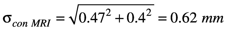 .
.


The total delineation uncertainty calculated in Equation 3 was compared to the measured 3D displacement of each target. In instances where the 3D displacement was less than the total delineation uncertainty (0.87 mm), the registration uncertainty was taken to be 0 mm.
A paired t-test was performed on the 3D displacement values for all 11 targets for the MRI-CT-CBCT and MRI-CBCT registrations.
Results
Multiple Spherical Targets
The mean 3D target displacement for 122 simulated spherical targets in 14 patients was 0.5 ± 0.3 mm with a maximum value of 1.3 mm (Figure 3a) when the registration was changed from MRI-CT-CBCT to MRI-CBCT. For the 122 spherical volumes, the PTV coverage change was 4.3 ± 5.0% with a maximum value of 32% (Figure 3b). Excluding the 0.28 mm sphere, the coverage change was 3.7 ± 3.5% with a maximum of 20% in the 8 mm diameter sphere group, indicating that for a given displacement, the smaller targets exhibited a larger coverage change.
Figure 3.
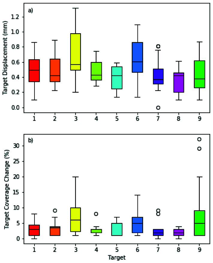
a) 3D Target displacement and b) Target coverage change by target for 14 patients. Targets 1-8 are 8 mm in diameter and target 9 is 0.28 mm in diameter.
Patient-Specific Targets
For 19 lesions in 14 patients, the mean 3D displacement of the target center coordinates was 0.6 ± 0.4 mm (maximum displacement = 1.9 mm) when the registration was changed from MRI-CT-CBCT to MRI-CBCT. The mean change in PTV coverage was 1.3 ± 1.6% (maximum change = 5%). The coverage of two GTVs changed by 0.1% and 0.5%; the GTV in all other targets retained original coverage (Table 2). The target displacements found in this experiment were similar to those found in experiment 1 (0.5 ± 0.3 mm, maximum = 1.3 mm).
Table 2.
Target displacement and coverage changes due to changing the registration workflow for 14 targets in 19 patients.
| Displacements (mm) | Coverage Change (%) | |||||
| Patient | x | y | z | r† | GTV | PTV |
| 1 | -1.4 | 0.1 | -0.3 | 1.4 | 0.0 | 2 |
| 1 | -0.7 | -0.5 | -0.4 | 0.9 | 0.0 | 1 |
| 2 | 0.4 | 0 | -1.9 | 1.9 | 0.0 | -1 |
| 3 | 0.1 | 0.6 | 1 | 1.2 | 0.0 | 5 |
| 4 | -0.2 | -0.1 | 0.2 | 0.3 | 0.0 | -1 |
| 5 | 0.3 | -0.2 | 0 | 0.4 | 0.0 | 1 |
| 6 | 0.1 | -0.3 | -0.6 | 0.7 | 0.0 | 5 |
| 7 | 0.5 | -0.2 | 0.4 | 0.7 | 0.5 | 0 |
| 8 | 0.1 | -0.6 | -0.2 | 0.6 | 0.0 | 2 |
| 9 | -0.1 | -0.6 | -0.1 | 0.6 | - | 3 |
| 10 | 0 | -0.1 | -0.5 | 0.5 | 0.1 | 1 |
| 11 | 0 | -0.2 | -0.2 | 0.3 | - | 0 |
| 11 | 0 | -0.4 | -0.1 | 0.4 | - | 0 |
| 11 | 0 | -0.3 | -0.1 | 0.3 | - | 0 |
| 11 | 0 | -0.3 | -0.1 | 0.3 | - | 1 |
| 11 | 0 | -0.2 | -0.1 | 0.2 | - | 0 |
| 12 | 0 | -0.2 | 0.4 | 0.4 | 0.0 | 1 |
| 13 | 0 | -0.7 | 0.1 | 0.7 | 0.0 | 3 |
| 14 | 0 | 0 | 0.1 | 0.1 | - | 0 |
| Mean | 0.6 | 0 | 1.3 | |||
| Standard Deviation | 0.4 | 0 | 1.6 | |||
r is the 3D vector displacement calculated from the x, y, and z displacements.
Phantom Study: Surrogate Target Localization
The mean 3D displacement between MRI-generated targets between the two workflows was 0.47±0.15 mm, similar to the results of the previous two experiments. The 3D displacement for MRI-generated targets to reference CBCT-generated targets and resulting registration uncertainty are listed in Table 3 for all targets for both the MRI-CT-CBCT and the MRI-CBCT workflows. The mean 3D displacement between the CBCT targets and MRI targets registered to the CBCT were 1.04 ± 0.47 mm for the MRI-CT-CBCT workflow and 0.89 ± 0.36 mm for the MRI-CBCT workflow. For 8 of the 11 targets, the 3D displacement was lower in the MRI-CBCT workflow than in the MRI-CT-CBCT workflow. The 3D displacement was less than the total delineation uncertainty (0.87 mm) in both workflows for 5 targets, in the MRI-CBCT workflow for 2 additional targets, and in the MRI-CT-CBCT for 1 additional target. The mean uncertainty due to registration alone was 0.50 ± 0.65 mm and 0.32 ± 0.47 mm for the two workflows (Table 3), as calculated using equation 4. A paired t-test indicated no statistical difference between the two registrations (p>0.05) for 3D displacement and registration uncertainty.
Table 3.
3D displacement between the two registration workflows.
| 3D disp (mm) | sreg(mm)† | |||
| Target | MRI-CT-CBCT | MRI-CBCT | MRI-CT-CBCT | MRI-CBCT |
| 1 | 1.00 | 0.73 | 0.50 | 0 |
| 2 | 0.73 | 1.00 | 0 | 0.50 |
| 3 | 1.07 | 0.73 | 0.62 | 0 |
| 4 | 1.32 | 1.09 | 0.99 | 0.65 |
| 5 | 0.70 | 0.85 | 0 | 0 |
| 6 | 0.44 | 0.14 | 0 | 0 |
| 7 | 0.73 | 0.65 | 0 | 0 |
| 8 | 0.77 | 0.85 | 0 | 0 |
| 9 | 2.00 | 1.52 | 1.80 | 1.24 |
| 10 | 0.87 | 0.79 | 0 | 0 |
| 11 | 1.82 | 1.45 | 1.60 | 1.16 |
| Mean | 1.04 | 0.89 | 0.50 | 0.32 |
| St. Deviation | 0.47 | 0.36 | 0.65 | 0.47 |
The uncertainty in the registration is calculated using equation 4, or taken to be 0 if result is imaginary.
No statistically significant difference between the registration uncertainty for the two workflows was observed, and the mean difference in target coordinates between workflows for each target was small (<0.5 mm) and consistent with the previous two experiments and literature.10 However, the maximum registration uncertainty was large (>1mm) for 2 targets in both workflows, perhaps due to the physical properties of how those targets were visualized in the two different imaging modalities.
Discussion
In experiment 1, it was observed that larger displacements occurred in the more posteriorly located targets (targets 3 and 6). Posterior targets experiencing larger displacements between workflows indicates that one or both workflows are more susceptible to registration uncertainties in the posterior region. This may be due in part to increased MR distortion in the periphery of the image, and in part due to the limited bony features/details in the posterior portion of the skull, compared to the level of detail anteriorly in the facial bones and inferiorly in the base of skull region. Chung et al. demonstrated that the co-registration was more accurate when the base-of-skull was included in the VOI, indicating the algorithm’s reliance on these detailed bony features.10 Ruschin et al. reported larger differences between the MRI-CT-CBCT and the MRI-CBCT workflows for locations over the whole CBCT image volume, compared to locations within the central 16 cm of the volume, which may exclude very posterior lesions.9
In experiments 1 and 2, there is a measurable difference between the two workflows, however neither workflow represents the ground-truth position of the target on the stereotactic image. The variation of results between the two workflow options can be used to inform treatment margin decisions. Target coverage changes for patient-specific target plans in experiment 2 were smaller than coverage changes for spherical volume plans in experiment 1 for one of two reasons. For very large lesions, the same displacement caused a relatively smaller coverage change because a smaller percentage of the PTV left the prescription isodose volume. Alternatively, for lesions smaller than the smallest collimator size (4 mm diameter), and irregularly-shaped targets, small target displacement may not result in coverage change due to lower selectivity of the plan. No meaningful relationship was observed between target x, y, or z coordinates, lesions size, or number of shots and the target displacement.
The target volume for patient 2 was located inferiorly beside the brainstem, and contouring was performed on a balanced steady-state gradient echo sequence (FIESTA) MRI. As the FIESTA MRI FOV was small, a full head T1 MRI was also obtained. In experiment 1, the full MRI was used to include all nine targets; in experiment 2, the small-FOV FIESTA MRI was used. It was observed that there were larger registration uncertainties when the small FOV image is used.
The diagnostic CT obtained for patient 7 showed a very different neck flexion compared to both the CBCT and MRI, and the target volume was located at the inferior and posterior edge of the cerebellum. Large differences were observed in the MRI-CT-CBCT workflow when the inferior border of the co-registration VOI did or did not include the first cervical vertebral body. The results presented here exclude the cervical spine due to the neck flexion differences. In clinical practice, care should be taken when selecting the co-registration VOI in cases where the patient position is different between imaging sets.
Quality assurance for the MRI scanner was performed to ensure the geometric distortion was acceptable for GK-SRS application. A Modus QUASARTM GRID3D radiosurgery test phantom was used to evaluate the geometric distortion of the scanner and scanning protocol. The mean and maximum absolute errors were 0.32 and 0.40 mm in left-right direction, 0.20 and 0.40 mm in superior-inferior direction, and 0.94 and 1.20 mm in anterior-posterior direction. Although there were distortions in the MRI images, the co-registration between MRI to either CBCT or diagnostic CT used the same rigid registration algorithm in LGP Gammaknife planning system. The expected impact of the MRI distortion on the accuracy of the co-registration to either diagnostic CT or stereotactic CBCT would be similar in magnitude, therefore it should not affect the results and conclusions obtained in this study.
Experiments 1 and 2 indicate that the magnitude of uncertainty between the two co-registration workflows is on average less than 1 mm, but can exceed 1 mm in some cases. The coverage change corresponding to a given displacement depends highly on the target size and shape, and the selectivity of the treatment plan. Experiment 3 indicates that neither workflow was significantly more accurate than the other in terms of overall target displacement between CBCT and MRI. Therefore, it can be determined that the vendor-recommended workflow of co-registering MRI directly to CBCT is sufficient for treatment planning purposes, especially if a margin is used for frameless GK Icon treatments. The MRI-CT and CT-CBCT co-registrations are easier to verify visually than a MRI-CBCT co-registration, and a CT may be appropriate in cases where the user has reason to believe that the MRI-CBCT co-registration maybe be difficult to verify. Such cases may include those with substantial artifacts, or when the CBCT or MRI volume is limited, which may occur when the patient is physically unable to slide superiorly enough in the mask-holder on the GK treatment couch. Patient neck position can vary between imaging sets, and should be examined prior to selection of the co-registration VOI.
In a White Paper by Elekta12 the estimated registration errors for CBCT-MRI and CT-MRI are up to 0.35 mm and 0.19 mm, respectively, for MRI slice thickness of 1 mm, which is the same slice thickness used in our study. It is noted in the White Paper that the registration errors are larger at the periphery of the images, due to MRI distortion, a finding endorsed by our results. There is some variability noted in the white paper; the standard deviations of the CBCT-MRI and CT-MRI co-registrations were up to 0.01 mm and 0.007 mm. This is smaller than our reported differences, so the co-registrations in this study were performed a single time. This study compared two different registration workflows commonly used in Gammakinfe frameless radiosurgery: MRI registered to stereotactic CBCT directly and MRI registered to CT and then to CBCT. Although part of the study methods can be used in other registration system, the very specific imaging modality (GK stereotactic CBCT) made this study very limited to one specific application.
The conclusions drawn from this study are also limited to our own institution, since the results are dependent on the scanners used to obtain the images. If other institutions repeat our experiment with different imaging datasets obtained from different MR and CT scanners, the magnitude of co-registration uncertainty may differ from that reported here due to the potentially larger variation originating from MRI scanners (distortion, spatial resolution, scanning parameters, etc.).
While differences exist in co-registration workflows used for frameless Gamma Knife Icon™ treatments, the addition of a CT in the workflow was not shown to significantly improve the co-registration accuracy. For routine cases, where the user can verify the co-registration with confidence, an additional CT for co-registration purposes is not necessary.
Acknowledgments
Authors’ disclosure of potential conflicts of interest
The authors have nothing to disclose.
Author contributions
Conception and design: Emily Hubley, Karen Mooney, Matthew Schelin, Wenyin Shi, Yan Yu, Haisong Liu
Data collection: Emily Hubley, Karen Mooney, Matthew Schelin, Haisong Liu
Data analysis and interpretation: Emily Hubley, Karen Mooney, Matthew Schelin, Wenyin Shi, Yan Yu, Haisong Liu
Manuscript writing: Emily Hubley, Karen Mooney, Matthew Schelin, Haisong Liu
Final approval of manuscript: Emily Hubley, Karen Mooney, Matthew Schelin, Wenyin Shi, Yan Yu, Haisong Liu
References
- 1. Wu A, Lindner G, Maitz AH, Kalend AM, Lunsford LD, Flickinger JC, Bloomer WD. Physics of gamma knife approach on convergent beams in stereotactic radiosurgery. Int. J. Radiat. Oncol. 1990;18(4):941–949. [DOI] [PubMed] [Google Scholar]
- 2. Li W, Cho Y-B, Ansell S, Laperriere N, Ménard C, Millar B-A, Zadeh G, Kongkham P, Bernstein M, Jaffray D, Chung C. The Use of Cone Beam Computed Tomography for Image Guided Gamma Knife Stereotactic Radiosurgery: Initial Clinical Evaluation. Int. J. Radiat. Oncol. Biol. Phys. 2016;96(1):214–20. [DOI] [PubMed] [Google Scholar]
- 3. Stieler F, Wenz F, Abo-Madyan Y, Schweizer B, Polednik M, Herskind C, Giordano FA, Mai S. Adaptive fractionated stereotactic Gamma Knife radiotherapy of meningioma using integrated stereotactic cone-beam-CT and adaptive re-planning (a-gkFSRT). Strahlentherapie und Onkol. 2016;192(11):815–819. [DOI] [PubMed] [Google Scholar]
- 4. Zeverino M, Jaccard M, Patin D, Ryckx N, Marguet M, Tuleasca C, Schiappacasse L, Bourhis J, Levivier M, Bochud FO, Moeckli R. Commissioning of the Leksell Gamma Knife ® IconTM. Med. Phys. 2017;44(2):355–363. [DOI] [PubMed] [Google Scholar]
- 5. Elekta AB. Brochure: Leksell Gamma Knife Icon Shaping a new era in intracranial radiosurgery. Art No. LPCIWB170830 v3.0 2018 [Google Scholar]
- 6. Studholme C, Hill DLG, Hawkes DJ. An overlap invariant entropy measure of 3D medical image alignment. Pattern Recognit. 1999;32(1):71–86. [Google Scholar]
- 7. Maes F, Collignon A, Vandermeulen D, Marchal G, Suetens P. Multimodality image registration by maximization of mutual information. IEEE Trans. Med. Imaging 1997;16(2):187–198. [DOI] [PubMed] [Google Scholar]
- 8. Joshi KC, Raghavan A, Muhsen B, Hsieh J, Borghei-Razavi H, Chao ST, Barnett GH, Suh JH, Neyman G, Kshettry VR, Recinos PF, Mohammadi AM, Angelov La. Fractionated Gamma Knife radiosurgery for skull base meningiomas: a single-institution experience. J. Neurosurg. 2019;46(6):E8 1-9. [DOI] [PubMed] [Google Scholar]
- 9. Ruschin M, Sahgal A, Soliman H, Myrehaug S, Tseng C-L, Bola R, Yeboah C, Sarfehnia A, Chugh B, Eriksson M, Nordström H, Lee Young. Clinical Image Coregistration Variability on a Dedicated Radiosurgery Unit. Neurosurgery 2019;85(1):167. [DOI] [PubMed] [Google Scholar]
- 10. Chung H-T, Kim JH, Kim JW, Paek SH, Kim DG, Chun KJ, Kim TH, Kim YK. Assessment of image co-registration accuracy for frameless gamma knife surgery. PLoS One 2018;13(3):e0193809. [DOI] [PMC free article] [PubMed] [Google Scholar]
- 11. Chung H-T, Park W-Y, Kim TH, Kim YK, Chun KJ. Assessment of the accuracy and stability of frameless gamma knife radiosurgery. J. Appl. Clin. Med. Phys. 2018;19(4):148–154. [DOI] [PMC free article] [PubMed] [Google Scholar]
- 12. Elekta White paper. Accuracy of co-registration of planning images with CBCT images (n.d.).
- 13. Seibert TM, White NS, Kim G, Moiseenko V, McDonald C, Farid N, Bartsch H, Kuperman J, Karunamuni R, Marshall D, Holland D, Sanghvi P, Simpson DR, Mundt AJ, Dale AM, Hattangadi-Gluth JA. Distortion inherent to magnetic resonance imaging can lead to geometric miss in radiosurgery planning. Prac Radiation Onocology. 2016;6:e319-e328 [DOI] [PMC free article] [PubMed] [Google Scholar]
- 14. Torfeh T, Hammoud R, Perkins G, McGarry M, Aouadi S, Celik A, Hwang KPm, Stancancello J, Petric P, Al-Hammadi N. Characterization of 3D geoemmmetric distortion of magnetic resonance imaging scanners commissioned for radiation therapy planning. MRI. 2016;34:645-653. [DOI] [PubMed] [Google Scholar]