Abstract
BACKGROUND AND PURPOSE:
The C1–2 intrathecal puncture is routinely performed when lumbar puncture is not feasible. Usage has steadily decreased in part because of the perceived high risk of injury to the cervical cord. Up to this point, vague fluoroscopic guidelines have been used, creating uncertainty about the actual needle location relative to the spinal cord. We present a novel osseous landmark to aid in C1–2 intrathecal puncture, corresponding to the posterior spinal cord margin on lateral fluoroscopic views. This landmark, which we have termed the “flare point,” represents the triangular “flaring” of the posterior C1 arch at its junction with the anterior arch.
MATERIALS AND METHODS:
Cervical spine CT myelograms were reviewed. High-resolution axial images were reformatted into the sagittal plane, and maximum-intensity-projection images were created to simulate a lateral fluoroscopic view. Tangential lines were drawn along the superior cortices of the anterior and posterior C1 arches, with the point of intersection used to approximate the flare point. Chart review was performed for all C1–2 punctures using the flare point technique in the past 3 years.
RESULTS:
Forty-two cervical myelograms were reviewed. The average flare point was 0.2 ± 0.5 mm posterior to the dorsal spinal cord margin. In 37/42 subjects, the flare point was localized posterior to the spinal cord. Targeting by means of the flare point was used in 16 C1–2 punctures without complications.
CONCLUSIONS:
The C1 posterior arch flare point accurately approximates the dorsal spinal cord margin on myelography. Targeting between the flare point and the spinolaminar line, at the mid-C1–2 interspace, allows safe and optimal needle positioning.
The C1–2 intrathecal puncture technique is performed when routine lumbar puncture is contraindicated or not feasible for any of the following reasons: severe spinal stenosis, arachnoiditis, infection overlying the skin, extensive posterior bony fusion, extensive neoplastic involvement, or tethered cord/spinal dysraphism.1 This technique was first described as an approach for cervical myelography in 1968, offering opacification above the level of a complete spinal block,2,3 and it first appeared in the neuroradiology literature in 1972.2,4 In recent years, this procedure has declined in use by many neuroradiologists, in part related to the perceived high risk of injury due to the proximity of the needle to the spinal cord (SC).1 There have been multiple reported cases of cervical cord puncture and injection of contrast into the SC, and a few cases of subarachnoid and subdural hemorrhage.5–12 These concerns, compounded by the frequency of myelography itself decreasing because of the superior contrast and spatial resolution of MR imaging, have led to this procedure being used sparingly. In fact, almost half of neuroradiology fellowship program directors responding to a 2009 survey reported that the C1–2 puncture technique had been performed at their institutions ≤5 times in the prior year.5 Although other novel techniques for collection of CSF, including atlanto-occipital and transforaminal lumbar puncture approaches, have been reported, they are not currently in widespread use.13–16
The cervical puncture can be safely performed under image guidance using either fluoroscopy or CT/CT fluoroscopy. With the conventional technique, a 22- or 25-ga spinal needle is advanced into the posterior third of the spinal canal at the level of the C1–2 interspace from a lateral approach, with the patient in a prone, supine, or decubitus position.1 The target is the posterior subarachnoid space, which has been found, on a prior myelographic fluoroscopy study of 100 patients, to measure an average of 4.3 mm from the posterior dura to the dorsal aspect of the SC.17 The SC itself has been reported to measure between 9 and 12 mm in the anteroposterior dimension (average, 10.3 mm), and the anterior subarachnoid space measures less than the posterior subarachnoid space from the dural margin (2.6 mm on average).17
Another consideration with the conventional C1–2 puncture technique is dural tenting, which was noted on cadaveric studies with the passage of the spinal needle into the posterior subarachnoid space.3 The amount of dural tenting measured between 5 and 10 mm, and sometimes more, before the dura was penetrated.3 Dural tenting was present on all studied routes of approach (anterior, midplane, and posterior); but most interesting, when the needle was advanced via the posterior approach to the posterior one-third of the spinal canal, the SC was rotated by the tented dura but was not punctured by the needle.3 Based on these anatomic studies, penetration of the posterior one-third of the canal from a lateral approach, approximately 5 mm anterior to the spinolaminar line (SL), has been considered the standard technique.18
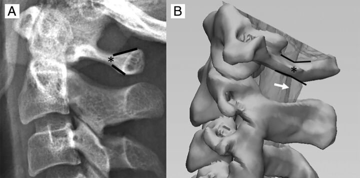
Although the posterior one-third of the spinal canal has been considered the safest approach, exact osseous landmarks correlating with the SC location have not been described in the literature, leading to some ambiguity in fluoroscopic targeting. We propose a novel osseous landmark on lateral views corresponding to the posterior SC margin, which we have termed the “flare point.” This osseous landmark is the triangular “flaring” of the posterior C1 arch at the transition of the lateral and posterior aspects of the arch (Fig 1). In the neurosurgical literature, this osseous transition has been described as a landmark for C1 lateral screw placement.19 The apex of the flare, the flare point (FP), is hypothesized to correspond with the posterior margin of the SC on lateral fluoroscopic views and has, up to this point, never been investigated, to our knowledge. In this study, we propose that the flare point is a reproducible osseous landmark that could approximate the position of the spinal cord to aid safe fluoroscopic needle placement during C1–2 puncture. We also report normative distances of the osseous canal and posterior subarachnoid space.
Fig 1.
A, The C1 arch has a unique osseous morphology demonstrating triangular flaring of the posterior arch (black lines). We have termed the origin of this posterior osseous flaring the “flare point” (asterisk). B, 3D image derived from a CT myelogram demonstrates the relationship of the C1 flare point (asterisk) and the dorsal border of the cervical cord, with the flare point location closely approximating the posterior border of the cord (white arrow) on the lateral view.
Materials and Methods
This retrospective study was conducted under an institutional review board–approved protocol and informed consent was waived. Investigators were compliant with the Health Insurance Portability and Accountability Act.
Subjects
We searched our PACS for cervical CT myelograms obtained at our institution within the past 3 years (2015–2017), and the 50 most recent studies were chosen to obtain the necessary power. Only studies performed with high-resolution, 1-mm-thick, axial slices were included for reformatting purposes. Studies were excluded if there was inadequate opacification of the thecal sac hindering definite delineation of the SC, surgical or congenital absence of the C1 posterior arch, presence of a subdural collection, or evidence of craniocervical osseous trauma that distorted normal anatomic relationships. Indications for the studies included contraindication for MR imaging, CSF leak, and degenerative disease with concern for stenosis.
Flare Point
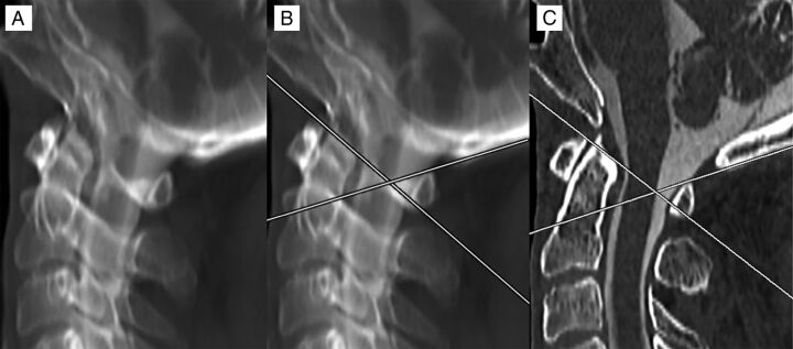
The relative location of the C1 posterior arch triangular FP to the dorsal spinal cord border was determined in all cases by the following methods: 1) A maximum-intensity-projection image was generated for each cervical myelogram using sagittal reformats of high-resolution (1-mm-thick) axial images. An MIP thickness of 3.5 cm was used to simulate the appearance of the C1 arch projecting over the spinal canal on a lateral fluoroscopic view, with alignment adjustments performed to ensure that the bilateral posterior arches precisely overlapped. 2) Two lines were drawn to approximate the angle of the anterolateral and posterior arches—the first line tangential to the superior cortex of the anterolateral arch and the second line tangential to the superior cortex of the posterior arch. 3) The FP apex was determined at the point where these lines intersected. 4) The distance of the FP apex to the dorsal margin of the spinal cord was measured. If this line was anterior to the cord, negative measurement values were used, and if the line was posterior to the cord, positive measurement values were used (Fig 2). Measurements were performed by a neuroradiology fellow and neuroradiology attending physician.
Fig 2.
Method of measurement for the C1 posterior arch FP. An MIP image was created of a high-resolution sagittal reformatted cervical CT myelogram. Alignment adjustments were performed to overlap the bilateral posterior arches (A). Lines were drawn tangential to the superior cortex of the anterolateral and posterior arches. Where these lines overlapped was considered the FP (B). The MIP was then converted back to a 1-mm-thick section to evaluate the position of the FP from the dorsal spinal cord, which, in this case, showed direct correspondence, measuring 0 mm (C).
Normative Distances
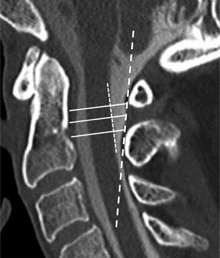
The following measurements were obtained on all studies: anteroposterior measurements of the osseous canal from the posterior C2 border to the SL as seen on fluoroscopy, anteroposterior measurements of the posterior SC border to the SL (PC-SL), and anteroposterior measurements of the posterior SC border to the posterior dura (PC-PD). Measurements of the posterior SC border to both the SL and the posterior dura were performed because the SL can be seen on fluoroscopy while the posterior dura cannot. This allowed comparison of the perceived space by fluoroscopy and the actual size of the posterior subarachnoid space by CT. Measurements were performed at 3 levels: the upper C1–2 interspace, the mid-C1–2 interspace, and the lower C1–2 interspace (Fig 3).
Fig 3.
Measurements were performed on high-resolution sagittal cervical myelogram CT reformatted images. A line was drawn along the posterior margin of the SC (short dashed white line), with a second line approximating the SL (long dashed white line). The osseous canal was measured along the upper, mid, and lower aspects of the C1–2 interspace (solid lines) from the posterior margin of the dens to the SL. Additional measurements were performed between the posterior cord to the SL and the posterior cord to the posterior dura at the upper, mid, and lower aspects of the C1–2 interspace (not shown).
Statistical Analysis
Power analysis was performed to determine an adequate number of subjects. Two-tailed t tests were performed to determine differences in the size of the posterior subarachnoid space between subjects with the FP falling posterior to the SC and subjects in whom the FP fell anterior to the dorsal SC margin. Intraclass correlation coefficient estimates and their 95% confidence intervals were calculated between 2 readers using a single-measure, absolute-agreement, 2-way mixed-effects model. Analyses were performed using SPSS, Version 25 (IBM, Armonk, New York).
Procedural Technique
Prior cervical imaging was reviewed for each patient for adequate subarachnoid space in the posterior spinal canal at C1–2, for position of the vertebral arteries, and for assessment of the C1 flare point with respect to the dorsal cord. Patients were positioned prone or supine with the neck neutral or slightly extended. A C-arm or biplane fluoroscopy was rotated to obtain a true lateral view centered at the C1–2 level. A metallic marker was used to localize a skin entry site midway between the spinolaminar line and flare point at the mid-C1–2 interspace. The overlying skin was prepped, draped, and anesthetized with 1% lidocaine via a 25-ga needle. A 22-ga Quincke needle (Halyard Health Global, Alpharetta, Georgia) was advanced toward the dorsal thecal sac under fluoroscopic guidance, with care taken to keep the needle tip from straying ventrally or dorsally. The needle depth was intermittently checked with anteroposterior fluoroscopy. When the needle reached the dura (approximated to be in line with the uncinate processes on an anteroposterior view), the bevel was rotated posteriorly to increase the likelihood of dural puncture. The needle was then advanced a few millimeters at a time under fluoroscopy, and the stylet was removed after each advancement until CSF return was noted. In our experience, it is common for the needle to reach the midline or just past midline on the anteroposterior view due to substantial dural tenting before entering the subarachnoid space.
Clinical Follow-Up
A search was performed for all C1–2 punctures performed using the FP technique in the past 3 years. Procedural images were evaluated, and a chart review was performed to determine whether complications were noted in the postprocedural note and first follow-up clinical note in outpatients or the discharge summary in inpatients.
Results
Subjects
Fifty subjects underwent CT cervical myelographic evaluation. Eight patients were excluded for the following reasons: Two had prior posterior C1 arch decompression, 2 had poor myelographic opacification, 2 had axial sections thicker than 1 mm, one had a C1 arch fracture, and one had a subdural collection. Forty-two cervical spine CT myelograms met all the criteria for evaluation (20 women; 56.0 ± 15.5 years of age) (Table), with most studies performed for CSF leak or evaluation of cervical stenosis when MR imaging was contraindicated. This exceeded the necessary subject size by power analysis (39 patients).
Demographics and normative distancesa
| Demographics/Distances | |
|---|---|
| Age (yr) | 56 ± 15.5 |
| Sex (F/M) | 20:22 |
| OC | |
| Upperb | 18.3 ± 2.9 |
| Mid | 17.8 ± 3.0 |
| Lower | 17.0 ± 2.9 |
| PC-SL | |
| Upper | 4.3 ± 1.5 |
| Mid | 4.1 ± 1.2 |
| Lower | 3.7 ± 1.0 |
| PC-PD | |
| Upper | 3.7 ± 1.4 |
| Mid | 4.4 ± 1.6 |
| Lower | 3.4 ± 1.2 |
| FP distance to cord | 0.2 ± 0.5 |
| PC-SL in subjects with anterior FP | |
| Upper | 3.8 ± 1.9 |
| Mid | 3.6 ± 1.6 |
| Lower | 3.3 ± 1.3 |
| PC-PD in subjects with anterior FP | |
| Upper | 3.2 ± 1.7 |
| Mid | 3.7 ± 1.7 |
| Lower | 2.9 ± 1.3 |
Note:—OC indicates osseous canal.
Data are means and all measurements are in millimeters, unless otherwise stated.
Refers to the position in the C1–2 interspace.
Flare Point
The FP was, on average, 0.2 ± 0.5 mm posterior to the dorsal margin of the spinal cord and corresponded exactly to the dorsal margin (0 mm) in 23/42 subjects. In the remaining subjects, the FP was within <1 mm of the dorsal spinal cord margin in 17/19, and in 2/19, the FP was >1 mm (1.5 and 2.2 mm, respectively) posterior to the dorsal spinal cord. In 5/42 subjects, the FP fell anterior to the dorsal spinal cord margin with distances ranging between 0.3 and 0.8 mm (Table and Fig 2). Readers had good reliability with an intraclass correlation coefficient single measure of 0.72 (95% CI, 0.53–0.84; P < .001).
Normative Distances
The osseous canal was largest at the upper portion of the C1–2 interspace (18.3 ± 2.9 mm), with a slightly smaller dimension at the midportion of the interspace (17.8 ± 3.0 mm) and the smallest diameter at the lower portion of the interspace (17.0 ± 2.9 mm). The PC-SL distances ranged from 4.3 mm at the upper interspace to 3.7 mm at the lower one. The largest dimension of the PC-PD was in the midportion of the interspace (4.4 ± 1.6 mm), which exceeded or equaled the PC-SL in 26/42 subjects (Table). The ratio of the PC-SL to the osseous canal ranged between 0.22 and 0.24, and the ratio of the PC-PD to the osseous canal ranged between 0.20 and 0.26.
Clinical Follow-Up
Since 2015, sixteen C1–2 punctures have been performed on 15 subjects at our institution, University of Utah Health, using the FP method for fluoroscopic targeting. Indications for C1–2 puncture included suspected basilar meningitis, tethered cord, spinal block, arachnoiditis, meningitis in the setting of spina bifida, as well as encephalopathy, multiple sclerosis, back pain, and elevated intracranial pressure in subjects without a feasible access for lumbar puncture. Evaluation of postprocedure notes in all subjects, as well as follow-up clinic notes in outpatients and discharge summaries in inpatients, revealed no immediate or delayed procedural complications using this technique (17.9 days on average between notes, with a range of 2–45 days).
Discussion
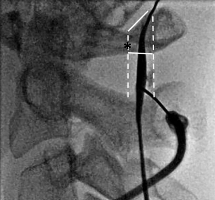
The practice of the C1–2 intrathecal puncture has steadily decreased in part because of its perceived high risk.1,5 However, this procedure demonstrates some advantages over other alternate routes of CSF collection, such as a lower theoretic risk of vascular injury than atlanto-occipital puncture. In the instances of spinal block, the C1–2 puncture may be the only option. Unlike transforaminal lumbar puncture, the C1–2 technique can be performed with the patient supine and can be performed in subjects with severe neuroforaminal narrowing who are not amenable to a transforaminal approach. We sought to determine whether the FP of the posterior C1 arch could be used as an osseous landmark to approximate the location of the dorsal spinal cord. Our results showed high accuracy of this landmark in approximating the dorsal spinal cord margin. This landmark was within 1 mm of the dorsal spinal cord margin in most of our subjects and rarely was located anterior to the dorsal margin of the cord. Because of a few instances in which the FP was anterior to the dorsal cord margin, targeting for cervical puncture should be placed midway between the FP and SL, not directly in line with the FP, to ensure that the needle does not contact the posterior SC margin (Fig 4).
Fig 4.
Intraprocedural fluoroscopic image demonstrating proper use of the flare point as an osseous landmark during a C1–2 puncture for a myelogram with the subject supine. The flare point (asterisk) is used to approximate the dorsal border of the spinal cord, and the needle is placed centrally between the dorsal cord border and the spinolaminar line (white dashed lines). Although the most capacious portion of the posterior subarachnoid space is in the mid-C1–2 interspace, successful puncture was performed in the slightly thinner lower portion of the interspace.
Subjects in whom the FP fell anterior to the dorsal margin of the spinal cord had, on average, a smaller dorsal subarachnoid space using both PC-SL and PC-PD compared with those with the FP behind the cord (P = .11 for both parameters) (Table). Even in these few subjects, the FP never fell greater than 1 mm anterior to the spinal cord, demonstrating that the accuracy of this landmark was maintained even in subjects with a smaller posterior subarachnoid space. We also found that the SL often underestimated the size of the posterior subarachnoid space at the mid-C1–2 interspace, with the dura extending up to 0.4 mm more posterior to the SL. The midportion of the C1–2 interspace was, overall, the largest portion of the posterior subarachnoid space, supporting targeting of this region.
The posterior subarachnoid space has frequently been thought to represent approximately one-third of the spinal canal, and this ratio has been historically recommended for targeting in C1–2 intrathecal puncture.1,18 In our study, we found the posterior subarachnoid space to be smaller than 33% (one-third), averaging between 22% and 23% of the total osseous canal when evaluating upper, mid, and lower portions of the C1–2 interspace. Only 4 subjects of 42 had a posterior subarachnoid space that measured at least 33% of the osseous canal, with the remaining 38 subjects demonstrating a smaller posterior subarachnoid space. One explanation for why overestimation of this space has not led to more complications could be the rotation of the spinal cord with dural tenting, which has been seen in postmortem studies.3 While studies have found no difference in the size of the posterior subarachnoid space between supine and prone positioning, flexion and extension can have an effect on the size of the posterior thecal sac, with a larger space for puncture on extension than in flexion.20 Most interesting, 1 study reported increased complications with neck hyperextension.6 Thus, a neutral to slightly extended neck positioning is used at our institution.
Although the posterior one-third of the spinal canal has been found to be the safest and most capacious subarachnoid target for cervical puncture, an aberrant vertebral artery coursing in this location can present a rare cause for hemorrhage with few reported cases.11,21 A posterior coursing vertebral artery is a rare anomaly, which, in a study of 164 patients, was only found to occur 2% of the time.6 An even rarer anomaly is vertebral artery partial duplication or fenestration, which was seen in only 1% of 1685 angiograms.22 The risk of PICA injury is extremely rare because fewer than 1% have been reported to extend below the C1 level.1,23–25 Use of the FP cannot entirely exclude vascular injury in these rare anomalous cases, and vascular injury remains a very rare risk.
Magnification is inherent in fluoroscopic imaging, which can distort measurements.26,27 This contrasts with CT images, which are calibrated to a phantom.28,29 Thus, measurements between modalities can vary due to geometric distortion. Although normative distances on this study were acquired by CT myelography rather than fluoroscopy, the flare point technique itself does not depend on transposition of distances from one technique to another. Rather, this technique depends on determination of the midway point between the flare point and spinolaminar line. Because this technique uses relative ratios rather than exact measurements, the flare point can be used fluoroscopically even if there are geometric measurement differences with CT.
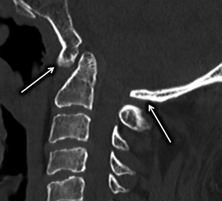
Limitations in the use of the FP include congenital anomalies of the posterior arch, specifically atlanto-occipital assimilation including both complete and incomplete forms (Fig 5). Other limitations include C1 arch fracture or surgical resection. Such conditions affect the morphology of the C1 posterior arch and therefore the FP approximation to the posterior SC, making it unreliable for fluoroscopic targeting. Study limitations include the retrospective design, small subject size, potential for inconsistencies in orientation of MIP reformats, and mild variations in patient positioning within the CT scanner.
Fig 5.
Sagittal CT of the cervical spine demonstrating congenital atlanto-occipital assimilation with 360° fusion of the C1 arch (arrows) resulting in complete absence of the FP.
Conclusions
The C1 posterior arch flare point accurately approximates the dorsal margin of the spinal cord on myelography and can be used to ensure a safe approach during C1–2 intrathecal puncture. Targeting midway between the flare point and the spinolaminar line, at the mid-C1–2 interspace, is recommended for safe and optimal needle positioning.
ABBREVIATIONS:
- FP
flare point
- PC-PD
posterior cord to the posterior dura
- PC-SL
posterior cord to the spinolaminar line
- SC
spinal cord
- SL
spinolaminar line
References
- 1. Gibbs WN, Skalski MR, Kim PE, et al. . C1–2 puncture: a safe, efficacious, and potentially underused technique. Neurographics 2017;7:1–8 10.3174/ng.1170183 [DOI] [Google Scholar]
- 2. Kelly DL Jr, Alexander E Jr. Lateral cervical puncture for myelography: technical note. J Neurosurg 1968;29:106–10 10.3171/jns.1968.29.1.0106 [DOI] [PubMed] [Google Scholar]
- 3. Orrison WW, Eldevik OP, Sackett JF. Lateral C1–2 puncture for cervical myelography, Part III: historical, anatomic, and technical considerations. Radiology 1983;146:401–08 10.1148/radiology.146.2.6687370 [DOI] [PubMed] [Google Scholar]
- 4. Heinz ER. Development of the C1–C2 puncture in neuroradiology: a historical note. AJNR Am J Neuroradiol 2005;26:5–6 [PMC free article] [PubMed] [Google Scholar]
- 5. Yousem DM, Gujar SK. Are C1–2 punctures for routine cervical myelography below the standard of care? AJNR Am J Neuroradiol 2009;30:1360–63 10.3174/ajnr.A1594 [DOI] [PMC free article] [PubMed] [Google Scholar]
- 6. Katoh Y, Itoh T, Tsuji H, et al. . Complications of lateral C1–2 puncture myelography. Spine 1990;15:1085–87 10.1097/00007632-199011010-00001 [DOI] [PubMed] [Google Scholar]
- 7. Lin J, Olivero WC, McCluney KW. Acute hydrocephalus following lateral C1–2 puncture: case illustration. J Neurosurg 1999;90(2 Suppl):277 [DOI] [PubMed] [Google Scholar]
- 8. Müller-Vahl H, Vogelsang H. Spinal cord injury caused by a lateral C1–2 puncture for cervical myelography. Eur J Radiol 1986;6:160–62 [PubMed] [Google Scholar]
- 9. Johansen JG, Orrison WW, Amundsen P. Lateral C1–2 puncture for cervical myelography, part I: report of a complication. Radiology 1983;146:391–93 10.1148/radiology.146.2.6687368 [DOI] [PubMed] [Google Scholar]
- 10. Mapstone TB, Rekate HL, Shurin SB. Quadriplegia secondary to hematoma after lateral C-1, C-2 puncture in a leukemic child. Neurosurgery 1983;12:230–31 10.1227/00006123-198302000-00020 [DOI] [PubMed] [Google Scholar]
- 11. Rogers LA. Acute subdural hematoma and death following lateral cervical spinal puncture: case report. J Neurosurg 1983;58:284–86 10.3171/jns.1983.58.2.0284 [DOI] [PubMed] [Google Scholar]
- 12. Simon SL, Abrahams JM, Sean Grady M, et al. . Intramedullary injection of contrast into the cervical spinal cord during cervical myelography: a case report. Spine 2002;27:E274–77 10.1097/00007632-200205150-00026 [DOI] [PubMed] [Google Scholar]
- 13. Gong D, Yu H, Yuan X. A new method of subarachnoid puncture for clinical diagnosis and treatment: lateral atlanto-occipital space puncture. J Neurosurg 2017. July 28. [Epub ahead of print] 10.3171/2017.1.JNS161089 [DOI] [PubMed] [Google Scholar]
- 14. Geraci AP, Black K, Jin M, et al. . Transforaminal lumbar puncture for intrathecal nusinersen administration. Muscle Nerve 2018. January 24. [Epub ahead of print] 10.1002/mus.26082 [DOI] [PubMed] [Google Scholar]
- 15. Weaver JJ, Natarajan N, Shaw DW, et al. . Transforaminal intrathecal delivery of nusinersen using cone-beam computed tomography for children with spinal muscular atrophy and extensive surgical instrumentation: early results of technical success and safety. Pediatr Radiol 2018;48:392–97 10.1007/s00247-017-4031-6 [DOI] [PubMed] [Google Scholar]
- 16. Nascene DR, Ozutemiz C, Estby H, et al. . Transforaminal lumbar puncture: an alternative technique in patients with challenging access. AJNR Am J Neuroradiol 2018;39:986–91 10.3174/ajnr.A5596 [DOI] [PMC free article] [PubMed] [Google Scholar]
- 17. Orrison WW, Sackett JF, Amundsen P. Lateral C1–2 puncture for cervical myelography, Part II: recognition of improper injection of contrast material. Radiology 1983;146:395–400 10.1148/radiology.146.2.6687369 [DOI] [PubMed] [Google Scholar]
- 18. Burt TB, Seeger JF, Carmody RF, et al. . Dural infolding during C1–2 myelography. Radiology 1986;158:546–47 10.1148/radiology.158.2.3753627 [DOI] [PubMed] [Google Scholar]
- 19. Kim JH, Kwak DS, Han SH, et al. . Anatomic consideration of the C1 laminar arch for lateral mass screw fixation via the C1 lateral lamina: a landmark between the lateral and posterior lamina of the C1. J Korean Neurosurg Soc 2013;54:25–29 10.3340/jkns.2013.54.1.25 [DOI] [PMC free article] [PubMed] [Google Scholar]
- 20. Bazylewicz MP, Berkowitz F, Sayah A. 3D T2 MR imaging-based measurements of the posterior cervical thecal sac in flexion and extension for cervical puncture. AJNR Am J Neuroradiol 2016;37:579–83 10.3174/ajnr.A4564 [DOI] [PMC free article] [PubMed] [Google Scholar]
- 21. Robertson HJ, Smith RD. Cervical myelography: survey of modes of practice and major complications. Radiology 1990;174:79–83 10.1148/radiology.174.1.2294575 [DOI] [PubMed] [Google Scholar]
- 22. Kowada M, Yamaguchi K, Takahashi H. Fenestration of the vertebral artery with a review of 23 cases in Japan. Radiology 1972;103:343–46 10.1148/103.2.343 [DOI] [PubMed] [Google Scholar]
- 23. Brinjikji W, Cloft H, Kallmes DF. Anatomy of the posterior inferior cerebellar artery: relevance for C1–C2 puncture procedures. Clin Anat 2009;22:319–23 10.1002/ca.20785 [DOI] [PubMed] [Google Scholar]
- 24. Tokuda K, Miyasaka K, Abe H, et al. . Anomalous atlantoaxial portions of vertebral and posterior inferior cerebellar arteries. Neuroradiology 1985;27:410–13 10.1007/BF00327604 [DOI] [PubMed] [Google Scholar]
- 25. Siclari F, Burger IM, Fasel JH, et al. . Developmental anatomy of the distal vertebral artery in relationship to variants of the posterior and lateral spinal arterial systems. AJNR Am J Neuroradiol 2007;28:1185–90 10.3174/ajnr.A0498 [DOI] [PMC free article] [PubMed] [Google Scholar]
- 26. van der Maas R, de Jager B, Steinbuch M, et al. . Model-based geometric calibration for medical x-ray systems. Med Phys 2015;42:6170–81 10.1118/1.4931964 [DOI] [PubMed] [Google Scholar]
- 27. Nickoloff EL. AAPM/RSNA physics tutorial for residents: physics of flat-panel fluoroscopy systems—survey of modern fluoroscopy imaging: flat-panel detectors versus image intensifiers and more. Radiographics 2011;31:591–602 10.1148/rg.312105185 [DOI] [PubMed] [Google Scholar]
- 28. Xu Y, Yang S, Ma J, et al. . Simultaneous calibration phantom commission and geometry calibration in cone beam CT. Phys Med Biol 2017;62:N375–90 10.1088/1361-6560/aa77e5 [DOI] [PubMed] [Google Scholar]
- 29. Yang H, Kang K, Xing Y. Geometry calibration method for a cone-beam CT system. Med Phys 2017;44:1692–706 10.1002/mp.12163 [DOI] [PubMed] [Google Scholar]


