Abstract
The size and curvature of the macaque brain present challenges for two photon laser scanning microscopy (2P-LSM). General access to the cortex requires 5-axis positioning over a range of motion wider than existing designs offer. In addition, movement artifacts due to physiological pulsations and bodily movement present particular challenges. We present a microscope and implant platform that allows for repeatable, motorized positioning and stable imaging at any point on the dorsal convexity of macaque cortex. While testing the system to image neurons expressing fluorescent proteins in an awake macaque, motion artifacts were limited to several microns.
I. Introduction
In conjunction with genetically encoded neural activity indicators, microscopes to perform in vivo two photon imaging in rodents have enabled cellular-resolution recording of cortical activity [1]. Existing microscopes typically offer only four degrees of freedom (DOF) or require the use of periscopes to target particular locations on the cranium. Imaging the primate brain on a large scale presents several new challenges. The objective lens must be able to travel between targets that are up to 10 cm apart, while remaining within one degree of normal to a cortical surface that exceeds 80 degrees of curvature. This requires five DOFs (three translational, two rotational) to control position and pointing direction over the range of movement. As a result, currently available instruments do not meet the structural challenges of imaging the non-human primate brain on a large scale. Furthermore, no existing designs robotically automate the positioning of all five DOFs, leading to poor repeatability and limited flexibility.
Cellular-resolution imaging in the awake primate also poses novel challenges with respect to motion artifacts. Postural readjustments in the macaque can produce forces orders of magnitude higher than those in a rodent. Rigidly fixing the head using metallic cranial implants can provide sufficient stability for imaging. However, the use of metal precludes magnetic resonance imaging (MRI), an important measurement for brain-scale investigations in non-human primates. Stability is further compromised by cardiopulmonary pulsations in the brain, which in primates exceed several millimeters in amplitude. Other work [2,3] has shown that pulsation-related artifacts can be limited over relatively small fields of view by pressing glass gently onto the cortical surface.
We present a microscope and implant system we term Monkey-MIMMS that extends the open-source Modular In vivo Multiphoton Microscopy System (MIMMS) to the brain of the macaque monkey. It robotically controls the relative pose (position and orientation) of the objective lens to the brain and can reliably center the objective lens to arbitrary targets on the dorsal convexity of the cortex. The cranial implant, while being made of MR compatible materials, provides excellent (< 2 μm) stability during imaging. We present results validating the use of this imaging system in one macaque under awake conditions.
II. System Description
A. Overview
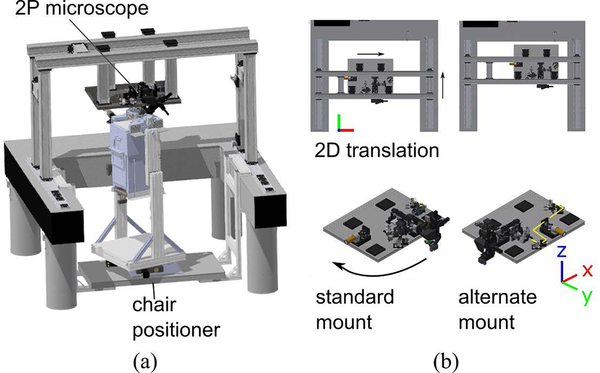
Our system, shown in Fig. 1a, consists of a microscope, a robotic chair positioner, and a head stabilization apparatus. When the monkey is mounted and his head fixed in the chair, the robotic positioner moves and rotates the subject to align a brain target with the objective lens. Optical tracking of the position and orientation (pose) of the microscope relative to the head allows the user to automatically orient the objective lens. Once a suitable pose is reached, the chair is rigidly attached to the microscope and optical table and imaging begins.
Figure 1:
(a) Model of microscope and chair positioner assembly. (b) (top inset) Translation range of the microscope table (top), and rotation range of the detection arm. (bottom inset) Standard and alternate mounting positions of the microscope.
B. Microscope Mechanics
Our microscope modifies the MIMMS platform to allow for significant freedom in positioning. The microscope, mounted on a gantry, can be manually translated on optical rails (ThorLabs) in the horizontal x and y directions through a range of 50 and 52 cm, without requiring beam realignment (Fig. 1b). The detection arm, which contains the objective lens (Nikon 0.8NA 16x), a fast objective scanner system (PI), and two photomultiplier tubes (Hamamatsu) is mounted onto an XYZ stage with 25 mm of travel along each axis that can also be tilted −20 to 70 degrees from vertical. However, the shape of the primate brain means that one rotational degree of tilt alone is insufficient for our positioning purposes, and two degrees of rotational freedom are required. The detection arm of the microscope can also be shifted from one face of the microscope table to another, again without beam realignment. Fig. 1b shows the “standard” and “alternate” mounting positions, which let microscope axis tilt within the (z,x) or (z,y) planes, respectively.
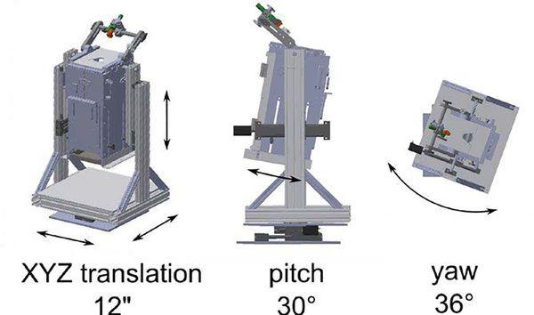
To automatically adjust the imaging target’s pose relative to the objective lens, a motorized five DOF positioner translates and rotates a macaque chair (Hybex Innovations). The positioner is capable of the movements shown in Fig. 2. All of the joints, excluding yaw, are driven by linear stages actuated by stepper motors (Oriental Motor). The positioner is controlled by a pair of microcontrollers (Arduino Mega 2560) interfaced to a PC via USB ports.
Figure 2:
Motorized axes of the chair positioner.
C. Head Fixation and Stabilization
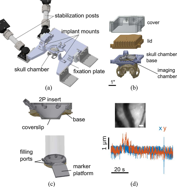
The chair positioner, while permitting flexible positioning, is not rigid enough for multiphoton imaging. To stabilize the subject once a suitable pose is found, the skull implant is rigidly fixed to a 1” thick U-shaped aluminum plate by three mount points shown in Fig. 3a. Two to four ball-and-socket joints connected to 1.5” diameter stainless steel posts are attached to the plate through stainless steel L-brackets. These posts are then attached with screws to the microscope table or an auxiliary gantry (not shown) by another set of ball joints.
Figure 3:
Stabilization. (a) Head fixation and stabilization assembly. (b) Skull chamber assembly. (c) Imaging chamber assembly. The two photon insert seals to the chamber base using a gasket. (d) Motion artifact characterization. The top inset shows the reference image with which the motion artifact was quantified for the entire sequence. Scale bar: 100 μm. Blue and red traces show horizontal brain movement in the x and y dimensions, respectively.
To rigidly fix the head, we implant a custom-designed chamber onto the skull (Fig. 3b). The implant conforms to the cranial curvature, which we extract from MR images. Ceramic screws fasten the implant to the skull, and the intervening space is sealed with dental cement (C&B Metabond, Parkell). The implant has a rear trapezoidal post and two bosses on either side for rigid fixation. The exposed skull in the center of the ring is populated by chambers over the brain sites of interest. Between experimental sessions and maintenance inspections, the chamber is covered and sealed with a lid. A 3D printed (FormLabs) cover/helmet is placed on top of the lid to protect against abrasion and impact damage.
D. Two-Photon Imaging Chamber Implant
A custom chamber system is used to support brain access. A low-profile base is chronically implanted in the central region of the skull implant ring. This base conforms to the skull shape and is compatible with additional modular components, such as electrocorticography (ECoG) arrays and penetrating electrode arrays [4].
For 2P-LSM, a specialized insert (Fig. 3c) attaches directly to the chamber base. The insert profile is tapered to permit the objective lens to translate within a 4 mm circle when imaging the cortex. A glass coverslip is bonded to the underside of the insert. To limit motion artifact due to physiological pulsations, the insert is custom-sized such that the glass presses gently ~0.5 mm onto the brain surface. The chamber interior is then filled with incompressible artificial cerebrospinal fluid (ACSF) using a pair of sealable ports. These measures eliminate nearly all pulsation-related motion artifacts.
E. Software Components
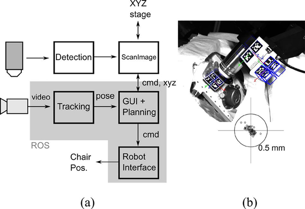
The microscope uses the ScanImage (Vidrio Technologies) set of tools for 2P imaging and controlling the microscope-attached XYZ stage. The chair positioner and optical control components are implemented using the Robot Operating System (ROS), which provides open-source tools for message passing, coordinate transformations, visualization, and optical tracking. Fig. 4a shows the system architecture. Video data from the tracking camera is processed and the relative objective → chamber pose is extracted. This is then displayed to the user through a “bullseye” view which displays the current angular and positional error with respect to desired target. A graphical user interface (GUI), written in Python, displays camera feeds and allows the user to reposition the robot. The system also allows the use of automated motion planning algorithms.
Figure 4:
Software for control and tracking. (a) Data flow diagram for the imaging and tracking/control systems. cmd: movement commands, xyz: position feedback, pose: relative position and orientation of the objective and the imaging chamber center. Chair Pos.: Chair positioner. (b) Tracking image. Blue cubes show the inferred poses of each marker, which are combined as pose estimates for marker-groups, shown as 3D axes. One set of cubes is thickened for clarity. Bottom inset: positional tracking error in the horizontal plane (parallel to the plane of imaging) of 64 points. 0.5 mm radius circle shown.
F. Optical Tracking
To aid in precisely orienting the objective over an area of interest, we track the relative pose between the objective and the imaging chamber using computer-vision (Fig. 4b). Kinematic markers (ARuCO) are adhesively attached to a platform on top of the 2P insert and on two surfaces of the piezo stage on the detection arm. Each marker is tagged with a pattern that uniquely identifies it. The markers are printed on adhesive labels (Avery UltraDuty GHS Chemical Labels) that can survive repeated autoclave cycles. The markers are tracked using a CMOS camera with a machine-vision lens (Edmund Optics). Intrinsic camera parameters are learned through an automated procedure in ROS (camera_calibration package). The ARuCO library is used for image processing and marker detection. The individual markers’ pose estimates are combined into single marker-groups, from which pose estimates for the objective and the chamber are computed. This helps with accuracy and also makes the system resistant to partial occlusion of some of the markers.
III. Validation Methods
A. Computer Vision Tracking Validation
To test the accuracy of computer-vision-based tracking offline, we performed an experiment with a mechanical replica of the skull chamber and imaging chambers mounted in the microscope arena. While tracking the microscope and the chamber, the XYZ stage was moved to a grid of 64 locations within a 25 mm cube. This moved the objective lens’ relative position to the chamber without changing their relative orientation. Treating the motor movements as ground truth, the tracked positions were recorded and rotated to the coordinate frame of the XYZ stage using least squares.
B. Surgical Procedures
All animal procedures were approved by New York University’s University Animal Welfare Committee (UAWC). One male macaca fascicularis was implanted with a skull chamber. The chamber was aligned to the skull using stereotaxic coordinates and was fastened to the skull using ceramic screws. Imaging chambers were implanted within the central region of the skull chamber over primary somatosensory cortex (S1) and primary visual cortex (V1). The chamber was positioned using MR-based targeting (Rogue Research) and secured to the skull. In a second procedure, a craniotomy was made the same size as the inner diameter of the chamber base, followed by a duratomy in which an artificial dura (AD) was inserted.
Viral injections of AAV2/1-hSyn1-GCaMP6s and AAV2/1-CaMKII-GCaMP6f were made in S1 and V1. The injections were made through the artificial dura with pulled glass pipettes.
C. Imaging Procedures
Four weeks after viral injections, imaging sessions commenced. The chair was placed in the microscope arena and the chair positioner was manipulated until the tracked orientation of the objective aligned with the imaging chamber’s cylindrical axis; the position was adjusted to be within 1” of the desired imaging position. For safety reasons, joint velocities were limited to 5 mm/s for prismatic joints and 9.3 °/s for revolute joints. This guided positioning step typically lasted 3–5 minutes. Using the microscope XYZ stage, the objective was positioned and focused on surface vasculature using the widefield light path. While the monkey sat, the horizontal motion artifacts due to postural adjustments were examined at 35 frames/s. Sub-pixel phase-correlation based registration [5] was used to extract the horizontal movement with respect to the mean image.
2P-LSM was performed using 940 nm excitation at 100–200 mW laser power. The objective was moved to the center of the imaging area of the chamber. Tiled Z-stacks were collected in a 500 μm-spaced grid of points within a 3 mm diameter circle up to 400 μm below the glass coverslip. Then, one region was selected and volumetric imaging was performed at various depths in the tissue. The scans consisted of 20 depths with 2 μm spacing.
D. Widefield Activity Measurement in S1
Prior to 2P imaging, widefield 1-photon fluorescence imaging was performed through a custom built tandem-lens epifluorescence microscope to confirm sites with functional viral expression. An imaging window was placed and filled with ACSF. Fluorescence image sequences were taken at 120 ms exposure during idle and stimulation conditions. Vibratory stimulation was delivered to the skin of the back using speaker cones attached to a custom-made jacket (Lomir). Stimuli of 3, 30, and 300 Hz, lasting 3 seconds with a 1 s ramp up/down were delivered at exponentially distributed intervals with a minimum wait time of 5 s. Imaging was performed.
IV. Results
Motion artifacts were measured to be very small (less than 1 μm) when the animal was quietly sitting (see Fig. 3d). Even during postural readjustments, the horizontal motion artifact was limited to 2.0 μm. An offline experiment was performed to measure the tracking accuracy of the computer vision system. The XYZ stage of the microscope was moved to a grid of locations. Tracking error was assessed in the (x, y) plane, which corresponds with the imaging plane. Fig. 4b (bottom inset) shows the errors for these points, along with a circle of radius 0.5 mm. The maximum 3D position error was found to be 405 μm, which is within one field of view of the 2P microscope (600 μm). Since the theoretical orientation does not vary across test points, the orientation error was the deviation from zero rotation. The maximum deviations were (0.11, 0.09, 0.08)° about the (x, y, z) axes.
To confirm viral expression, vibratory stimuli were delivered to a spot on the skin that evoked fluorescence changes. Fig. 5a shows an example fluorescence image and ΔF/F trace. Stimulus onsets are shown as vertical lines. We performed 2P-LSM in the chamber over the site shown in Fig. 5a. Fig. 5b shows a composite of images formed from an automated scan of the cortical surface formed from 29 individual Z-stack scans. One region was selected and further imaged to reveal cells with GCaMP6 expression at depths down to 220 μm. Fig. 5c shows an image from a single plane showing cell bodies and dendritic arbors. A close-up (Fig. 5d) shows a group of cell bodies with characteristic “donut” shapes.
Figure 5:
Sample images. (a) Top inset: Widefield fluorescence image of an area of GCaMP6 expression in l. Bottom inset: example trace of fluorescence changes in the region of interest. Scale bar: 1 mm. (b) 2P surface composite of the same region formed by an automated iterative scan of the area. Scale bar: 1 mm. (c) Single plane scan of one 2P field of view. Scale bar: 100 μm (d) Close-up of a cluster of cell bodies. Scale bar: 50 μm.
V. Conclusion
We have presented an adaptation of a standard 2P microscope that enables flexible, automated positioning. Using marker-based tracking, the microscope can be placed within 0.5 mm of a desired location on the head within 0.11° of the correct orientation. Moreover, our head fixation hardware and cranial implants rigidly stabilize the brain, reducing horizontal vibrations to 1/5 the diameter of a typical cell body.
Although the imaging system described above was validated using a single chamber, it can in principle allow fast (~1 min) switching between distant imaging sites. Although for these initial tests, a slow positioner velocity was used, this was for safety reasons since the joints were user-controlled. With automated motion planning, this constraint could be relaxed. With these tools, a host of neuroscientific questions can be addressed in the non-human primate model.
Acknowledgment
We thank Miranda Milner for help in CAD modeling. We also thank Nia Boles, Marsela Rubiano, Sameer Sabharwal-Siddiqi, and Vincent Sanchez for assistance in chamber maintenance. The MIMMS platform was originally developed at Janelia Research Campus, HHMI.
Research supported by National Institutes of Health award U01-NS103518 and a grant from the Simons Foundation (325548, Pesaran).
Contributor Information
John Choi, Center for Neural Science at New York University, New York, NY 10003 USA.
Vasily Goncharov, ID&F Janelia Research Campus, Howard Hughes Medical Institute, Houston, TX 77005 USA.
Jessica Kleinbart, Center for Neural Science at New York University, New York, NY 10003 USA.
Amy Orsborn, Center for Neural Science at New York University, New York, NY 10003 USA.
Bijan Pesaran, Center for Neural Science at New York University, New York, NY 10003 USA.
References
- [1].Lin MZ and Schnitzer MJ, “Genetically encoded indicators of neuronal activity,” Nature Neuroscience, vol. 19, no. 9 pp. 1142–1153, 2016. [DOI] [PMC free article] [PubMed] [Google Scholar]
- [2].Li M, Liu F, Jiang H, Lee TS, and Tang S, “Long-Term Two-Photon Imaging in Awake Macaque Monkey,” Neuron, vol. 93, no. 5, p. 1049–1057.e3, 2017. [DOI] [PubMed] [Google Scholar]
- [3].Trautmann E, O’Shea DJ, Shrestha S, Lin S, Ryu S, and Shenoy K, “Design of an implantable artificial dural window for chronic two-photon optical imaging in non-human primates,” in Proceedings of the Annual International Conference of the IEEE Engineering in Medicine and Biology Society, EMBS, 2015, vol. 2015–Novem, pp. 7554–7557. [DOI] [PMC free article] [PubMed] [Google Scholar]
- [4].Orsborn AL, Wang C, Chiang K, Maharbiz MM, Viventi J, and Pesaran B, “Semi-chronic chamber system for simultaneous subdural electrocorticography, local field potentials, and spike recordings,” in International IEEE/EMBS Conference on Neural Engineering, NER, 2015, vol. 2015–July, pp. 398–401. [Google Scholar]
- [5].Pachitariu M, Stringer C, Schröder S, Dipoppa M, Rossi LF, Carandini M, and Harris KD, “Suite2p: beyond 10,000 neurons with standard two-photon microscopy,” bioRxiv, p. 61507, 2016. [Google Scholar]


