Abstract
Scaffolds, three-dimensional (3D) substrates providing appropriate mechanical support and biological environments for new tissue formation, are the most common approaches in tissue engineering. To improve scaffold properties such as mechanical properties, surface characteristics, biocompatibility and biodegradability, different types of fillers have been used reinforcing biocompatible and biodegradable polymers. This paper investigates and compares the mechanical and biological behaviors of 3D printed poly(ε-caprolactone) scaffolds reinforced with graphene (G) and graphene oxide (GO) at different concentrations. Results show that contrary to G which improves mechanical properties and enhances cell attachment and proliferation, GO seems to show some cytotoxicity, particular at high contents.
Keywords: Biomanufacturing, Graphene, Graphene oxide, Poly(ε-caprolactone), Scaffolds, Tissue engineering
1 Introduction
Large scale bone defects caused by bone cancer surgeries, accidents, injuries, infections and chronic health conditions, represent relevant clinical problems. Due to the limited regenerative capabilities of bone, current clinical therapies, in most cases based on the use of biological grafts, are not effective. Scaffold-based bone tissue engineering is an alternative approach with potential to overcome major limitations of biological grafts such as pain and morbidity in donor sites, limited quantity and availability, deep infection and hematoma risk (autografting), rejection, diseases transmission, limited supply (allografting), and ethical problems (xenografting). Scaffolds are three-dimensional (3D) biocompatible and biodegradable porous physical substrates for cells to attach, proliferate, and differentiate[1-3]. They must have adequate mechanical properties, geometry and morphology, surface characteristics and must be easily sterilized[4]. Their capacity to stimulate cells is also another important requirement. Due to the piezoelectric and reverse piezoelectric nature of bone, electrical signals are critical physiological stimuli that strongly affect cell behavior controlling cell migration, adhesion, differentiation, DNA synthesis, and protein secretion[5]. A wide range of polymers (e.g., poly(glycolic acid), poly(lactic acid), poly(ε-caprolactone) [PCL], and poly(lactide-co-glycolide)), ceramic materials (e.g., hydroxyapatite [HA] and β-tricalcium phosphate [TCP]), and composites have been used to produce bone scaffolds[6-8]. Multiple additive manufacturing technologies such as material extrusion, powder bed fusion, vat photopolymerization, and material or binder jetting techniques have been explored for the fabrication of bone tissue engineering scaffolds using a wide range of materials[9-11]. PCL, a semi-crystalline aliphatic polymer, has been successfully used by our group for bone tissue engineering scaffolds. We investigated the degradation kinetics of such scaffolds as a function of scaffold topology[12,13], the effect of processing conditions on the morphological development/microstructure formation during the printing process[14,15] and surface modification strategies to improve cell attachment, proliferation, and differentiation[16,17]. To improve the bioactivity of PCL scaffolds, PCL/HA and PCL/TCP scaffolds containing different amounts of ceramic particles were also investigated and the results showed that scaffolds containing HA present better human adipose-derived stem cells (hADSCs) attachment and proliferation and TCP scaffolds present improved mechanical properties. Despite the promising results obtained with these scaffolds, they are not electrically conductive, which is a limiting characteristic of bone regeneration. To address this issue, our group also developed strategies to induce electroconductive properties on PCL-based scaffolds by mixing PCL with conductive polymers[18] or with low concentration of other conductive materials such as graphene (G) and carbon nanotubes (CNTs)[17,19,20].
The previous studies demonstrated that the addition of low concentration of G (up to 1 wt.%), two-dimensional single-atom-thick sheets of carbon atoms bound in hexagonal lattice structures[21], can enhance the hydrophilicity, topology, and the mechanical property of PCL scaffolds[17,22]. The in vitro biological studies show that cell attachment, proliferation, and differentiation of hADSCs can be stimulated by the addition of G fillers[20,22,23]. Huang et al.[24] investigated the use of additive manufacturing to produce scaffolds containing different loadings of multi-walled CNT (MWCNT) (0.25, 0.75, and 3 wt.%). Results showed that the addition of MWCNTs enhances protein adsorption, mechanical, and biological properties. Recently, Huang et al.[25] investigated 3D printed porous scaffolds containing aligned MWCNTs and nano-HA (nHA), mimicking the natural bone tissue from the nanoscale to macroscale level. MWCNTs with similar dimensions as collagen fibers were coupled with nHA and mixed within a PCL matrix. PCL/HA/MWCNTs scaffolds exhibited increased mechanical properties, cell proliferation, osteogenic differentiation, and scaffold mineralization. Wang et al.[20] assessed PCL, PCL/G, and PCL/CNTs from chemical, physical, and biological points of view. Results confirmed that the addition of both G and CNT allows the fabrication of scaffolds with improved properties. It also showed that scaffolds containing G present better mechanical properties and high cell-affinity improving cell attachment, proliferation, and differentiation.
Graphene oxide (GO), a single monomolecular layer of graphite with many functionalities including the presence of carbonyl, carboxyl, epoxide, and hydroxyl groups[26], is a candidate material for the fabrication of electro-active scaffolds. Scaffolds containing GO (concentrations up to 1.5 wt.% and 5 mg/mL) produced through a wide range of non-additive manufacturing techniques have been reported[27-29]. Results suggest that due to the presence of GO produced scaffolds presented no cytotoxicity against hADSCs, controlled degradation, and enhanced protein adsorption. This paper investigates the mechanical, wettability, and biological properties of PCL scaffolds containing different concentrations of G or GO produced through material extrusion additive manufacturing[30].
2 Materials and methods
2.1 Scaffolds fabrication
G nanosheets were synthesized from graphite by water-assisted liquid-phase exfoliation as reported before by Wang et al. and GO nanosheets (Sigma-Aldrich, UK) were purchased from Sigma-Aldrich. G and GO nanosheets were mixed with PCL pellets (CAPA 6500) (Perstorp, UK) through a melt blending process at different concentrations (1 wt.%, 2 wt.%, and 3 wt.%). PCL pellets and reinforcements were heated at 150°C and mixed together in a crucible for 30 min. The material was stirred for 30 min to disperse the fillers homogenously. After cooling down for 3 h, the mixed materials were then cut into pellets and prepared for printing. Scaffolds were produced using the screw-assisted material extrusion additive manufacturing system 3D DiscoveryTM Evolution Bench-top (regenHU, Switzerland). The following design and processing parameters were considered: Fiber layout of 0°/90°, melt temperature of 90°C, screw rotation rate of 8 rpm, deposition velocity of 13 mm/s, slice thickness of 270 μm, and pressure of 6 bars. These parameters are considered to guarantee constant filament diameter of 330 μm after printing.
2.2 Morphological evaluation
Morphological characterization was performed through scanning electron microscopy (SEM). FEI Quanta 250 SEM (Thermo Fisher Scientific, USA) was used to capture images of both the top surface and cross-section of the scaffolds, using an accelerating voltage of 10 kV. Before image capturing, the scaffolds were cut into 3 mm blocks and coated with a thin layer of metal (10 nm gold) using the EMITECH K550X sputter coater (Quorum Technologies, UK). The obtained images were processed by ImageJ (NIH, USA).
2.3 Mechanical evaluation
To determine the mechanical properties of the scaffolds, according to American Society for Testing and Materials standards[31,32], uniaxial compression tests were conducted on the INSTRON X testing system (High Wycombe, UK) with a 100 N load cell. The scaffolds were cut into blocks of 3 mm of width, 3 mm of length, and 4mm of height. Compression tests were performed in dry state with the strain ranging from 0 to 0.3 mm/mm (30%) and a displacement rate of 0.5 mm/min. Force F and corresponding displacement ∆h were measured by sensors while the samples were compressed, and then transformed into stress σ and strain ε values. The compressive modulus and compressive strength of the scaffolds were calculated using the software Origin (OriginLab, USA).
2.4 Surface wettability evaluation
Apparent water-in-air contact angle (WCA) tests were carried out with a KSV CAM 200 system (KSV Instruments, Finland) to evaluate the surface hydrophilicity of the scaffolds. 2 ml of distilled water was dropped on the surface of the scaffold using a micrometric liquid dispenser (Hamilton, USA) and the drop shape was recorded with a DMK 21F04 FireWire monochrome camera (Imaging Source, Germany). Attention Theta software (Biolin Scientific, Sweden) automatically calculates the contact angle.
2.5 Biological studies
In vitro, biological studies were conducted using hADSCs (Invitrogen, USA). hADSCs were defrosted and cultured in MesenPRO RS™ basal medium (Thermo Fisher Scientific, USA) in T75 cell culture flasks (Sigma-Aldrich, UK) at standard conditions (37°C, 5% CO2 concentration, and 95% humidity) in a New Brunswick® Galaxy 170 R incubator (Eppendorf, USA). Cells were harvested at approximate 80% confluence using 0.05% trypsin-EDTA (Invitrogen, USA) and Centra® MP4 Refrigerated Centrifuge (Thermo Fisher Scientific, USA) (1200 rpm, 150 s) before cell seeding. Cells ranging from passage 2 to 6 were considered for biological evaluation.
Before cell seeding, scaffolds were sterilized in 99.8% ethanol (Thermo Fisher Scientific, USA) for 4 h, transferred to a 24-well plate, and rinsed with Dulbecco’s Phosphate-Buffered Saline (PBS) (Thermo Fisher Scientific, USA). 50000 cells (counted by Cellometer Auto 1000 Bright Field Cell Counter [Nexcelom Bioscience, USA]) in 0.8 mL medium were seeded on each scaffold sample and empty well (control group).
The viability and proliferation of cells were evaluated at 1, 3 and 7 days after cell seeding using the Alamar Blue assay, which can quantitatively monitor the metabolic activity of cells and potential cytotoxicity of scaffolds[33]. At each particular time point, 1 mL of medium containing 0.001% Alamar Blue (Sigma-Aldrich, UK) was added to each well and incubated at standard conditions for 4 h. Then, 150 μL liquid from each well was transferred into a 96-well plate and the fluorescence intensity was measured by a Multi-Detection Microplate Reader Synergy HT (BioTec, USA) (excitation wavelength of 530 nm and the emission wavelength of 590 nm).
For the preparation of confocal imaging, the pre-fixed (with 10% neutral buffered formalin) cell-seeded scaffolds were rinsed in PBS and added with 1 ml 0.1% Triton X-100 (Sigma-Aldrich, UK) to permeabilize cell membrane. Afterward, 1 ml of 5% w/w fetal bovine serum (Sigma-Aldrich, UK) in PBS was added to each sample and incubated at room temperature for 1 h to block non-specific binding. The samples were then rinsed and added Alexa Fluor 488 phalloidin (Thermo Fisher Scientific, USA) and 4’ 6-diamidino-2-phenylindole (Thermo Fisher Scientific, USA) under the manufacturer’s recommended concentration, and incubate in the dark. The images were captured by a Leica SP8 LIGHTNING confocal microscope (Leica, Germany).
2.6 Data analysis
All experiments have at least three repeats (n ≥ 3) and data represent mean ± standard deviation. One-way analyses of variance with Tukey test were applied using Origin software. The significance levels were set at * P < 0.05, ** P < 0.01, and *** P < 0.001 compared with control (PCL), # P < 0.05, ## P < 0.01, and ### P < 0.001 compared with different concentrations of the same material, & P < 0.05, && P < 0.01, and &&& P < 0.001 compared with the same concentration of different materials.
3 Results and discussion
3.1 Morphological evaluation
SEM images of the fiber surface are presented in Figure 1. Actual scaffold images and both top surface and cross-section SEM images of the scaffolds are presented in Figure 2. As observed, the addition of G or GO seems to create a smooth surface on the printed filaments. Table 1 shows that the printed scaffolds present an average filament diameter of 333.33 ± 8.32 μm (the designed value was 330 μm), regular square pores with an average pore size of 336.65 ± 16.92 μm in the vertical direction (top surface, the designed value was 350 μm), and 218.69 ± 22.03 μm in the horizontal direction (cross-section, the designed value was 210 μm). These differences between the measured values and designed values are due to rheological effects (viscosity, shear-thinning, and viscoelastic properties) associated to the different material compositions.
Figure 1.
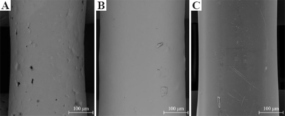
Scanning electron microscopy images of the fiber surface on (A) poly(ε-caprolactone), (B) 3 wt.% graphene, and (C) 3 wt.% graphene oxide scaffolds.
Figure 2.
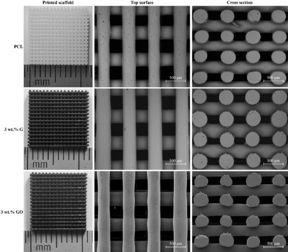
Actual images, top surface, and cross-section scanning electron microscopy images of different printed scaffolds.
Table 1.
Fiber diameter and pore size values of the scaffolds considering different material compositions (n=9).
| Scaffolds | Fiber diameter (μm) | Pore size (vertical) (μm) | Pore size (horizontal) (μm) |
|---|---|---|---|
| Designed | 330 | 350 | 210 |
| PCL | 323.23±19.68 | 341.38±16.03 | 211.82±19.51 |
| 1 wt.% G | 338.00±6.78 | 319.13±5.57 | 203.60±15.89 |
| 2 wt.% G | 337.45±12.58 | 316.63±12.82 | 183.10±7.53 |
| 3 wt.% G | 342.33±16.69 | 329.38±23.00 | 221.40±16.98 |
| 1 wt.% GO | 332.56±14.61 | 340.54±16.48 | 246.57±12.56 |
| 2 wt.% GO | 320.67±18.87 | 366.25±30.28 | 242.70±8.53 |
| 3 wt.% GO | 339.05±27.34 | 343.23±39.56 | 221.63±17.17 |
3.2 Mechanical evaluation
Figure 3 represents the strain-stress curve and Figure 4 represents both compressive modulus and compressive strength values of PCL, PCL/G, and PCL/GO scaffolds. As observed, the addition of G significantly increases the compressive modulus from 78.32 ± 5.22 MPa (PCL) to 136.74 ± 4.55 MPa (3 wt.% G). The same trend can be found in terms of compressive strength, which increases from 2.69 ± 0.27 MPa (PCL) to 3.13 ± 0.13 MPa (3 wt.% G). All PCL/G scaffolds were statistically different from the PCL scaffolds.
Figure 3.
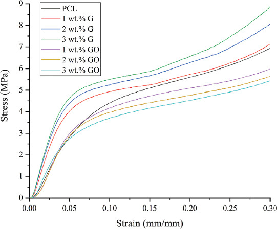
Strain-stress curve of different scaffolds.
Figure 4.
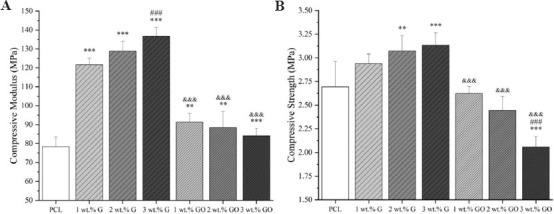
Mechanical properties of scaffolds with different material composition (A) compressive modulus; (B) compressive strength (n = 5).
In the cases of PCL/GO scaffolds, the addition of GO slightly increased the compressive modulus from 78.32 ± 5.22 MPa (PCL) to 91.35 ± 4.51 MPa (1 wt.% GO), which then decreased to 84.08 ± 3.93 MPa (3 wt.% GO). In terms of compressive strength, the incorporation of GO fillers decreased the compressive strength from 2.69 ± 0.27 MPa (PCL) to 2.06 ± 0.11 MPa (3 wt.% GO). All PCL/GO results are significantly different from PCL/G, but not significantly different from PCL scaffolds.
In the case of G fillers, the increase in the mechanical properties can be attributed to the intrinsic properties of the fillers, dispersion and distribution of the fillers, and adhesion between fillers and matrix (PCL). However, in the case of GO fillers, the addition of fillers into the matrix over a certain critical value (reported as 0.1 wt.%) the GO nanosheets become too close to each other[34]. Due to Van der Waals forces, GO fillers tend to stack together making it more difficult to disperse and limiting load transfer[34].
Results also show that the fabricated scaffolds have mechanical properties in the same order of magnitude as human trabecular bone. Depending on gender and age, human trabecular bone presents compressive modulus ranging from 50 to 1500 MPa with the mean value of 194 MPa, and the compressive strength ranging from 1 to 30 MPa with the mean value of 3.55 MPa[35-38].
3.3 Surface wettability evaluation
Table 2 shows the WCA results at 0, 5, and 10 s after the water droplet was dropped on the samples surfaces. PCL scaffolds present the highest contact angle value of 89.28 ± 1.36° at 0 s which slightly decreases to 87.91 ± 1.71° after 10 s, typical of hydrophobic surfaces. In the case of scaffolds containing G, the values are lower than PCL scaffolds, ranging between 87.25 ± 0.82° (1 wt.% G) to 84.12 ± 1.44° (3 wt.% G) at 0 s and 86.10 ± 0.74° (1 wt.% G) to 82.40 ± 0.92° (3 wt.% G) after 10 s. In the case of scaffolds containing GO, the values are also lower than PCL scaffolds, ranging between 82.79 ± 0.35° (1 wt.% GO) and 82.03 ± 1.47° (3 wt.% GO) at 0 s. After 10 s, the values vary between 81.73 ± 0.06° (1 wt.% GO) and 81.52 ± 1.52° (2 wt.% G). Changes on the wettability, particularly in the case of GO, can be attributed to the hydrophilic O, OH, and COOH groups of the GO nanosheets. These results also show that the addition of G and GO has a minor effect on the contact angle.
Table 2.
WCA results of scaffolds with different carbon material contents after 0, 5, and 10 s (n=5).
| Time | PCL | 1 wt.% G | 2 wt.% G | 3 wt.% G | 1 wt.% GO | 2 wt.% GO | 3 wt.% GO |
|---|---|---|---|---|---|---|---|
| 0 s | 89.28±1.36° | 87.25±0.82° | 84.13±0.50° | 84.12±1.44° | 82.79±0.35° | 82.22±0.89° | 82.03±1.47° |
| 5 s | 88.48±1.82° | 86.41±0.81° | 83.73±0.66° | 83.64±1.43° | 82.07±0.35° | 81.62±1.48° | 81.67±1.28° |
| 10 s | 87.91±1.71° | 86.10±0.74° | 83.30±1.06° | 82.40±0.92° | 81.73±0.06° | 81.52±1.52° | 81.57±1.26° |
WCA: Water-in-air contact angle
3.4 Biological studies
Confocal microscopy images (Figure 5), showing cell nuclei stained blue and cell actin stained green, suggest that all scaffolds can support cell attachment and proliferation along the fibers. Figure 6 shows the metabolic activity of cells at different time points after cell seeding. In this figure, the fluorescence intensity is proportional to the number of metabolically active cells.
Figure 5.

Confocal microscopy images of cell-seeded scaffolds (A) poly(ε-caprolactone), (B) 3 wt.% graphene, and (C): 3 wt.% graphene oxide, 7 days after cell seeding.
Figure 6.
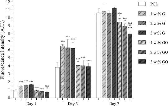
Cell viability/proliferation results 1, 3, and 7 days after cell seeding on different scaffolds (n = 5) (the fluorescence intensity of cell-seeded PCL scaffolds at day 1 was set as 1).
As observed, at day 1 and day 3 after cell seeding, PCL/G scaffolds show significantly higher fluorescence intensity than PCL scaffolds and PCL/GO scaffolds, but there is no statistical difference between the scaffolds with different filler contents. After 7 days of cell seeding, there is no statistical difference between PCL scaffolds and PCL/G scaffolds. However, in the case of PCL/GO scaffolds, the fluorescence intensity is significantly lower than PCL scaffolds and PCL/G scaffolds. Results seem to indicate that the fluorescence intensity decreases with the addition of GO content.
4 Conclusions
This paper investigates additively manufactured PCL, PCL/G, and PCL/GO scaffolds for bone repair applications. Printed scaffolds presented similar pore size and filament diameter as designed. Results show that PCL/G scaffolds present high compressive modulus and strength. The addition of GO reduces the WCA but after 7 days of cell seeding PCL/GO exhibit reduced cell metabolic activity than PCL and PCL/G scaffolds suggesting potential cytotoxicity effects particularly for high levels of GO. Results also show that both G and GO fillers can improve the surface wettability of the scaffolds, showing hydrophilicity. Moreover, from the biological evaluation, it was possible to observe that the G fillers promote cell attachment, viability, and proliferation while GO fillers reveal an opposite trend.
Acknowledgments
Author Weiguang Wang acknowledge the funding Rosetrees and Stoneygate Trust Young Enterprise Fellowship (Ref: A2750/M874) provided by Rosetrees Trust (charity number 298582) and Stoneygate Trust (charity number 1119976). This project has been also supported by the University of Manchester and the Engineering and Physical Sciences Research Council (EPSRC) of the UK, the Global Challenges Research Fund (GCRF), grant number EP/R01513/1.
Conflicts of interest
The authors declare that they have no conflicts of interest.
References
- 1.Langer R, Vacanti JP. Tissue Engineering. Science. 1993;260:920–6. doi: 10.1126/science.8493529. [DOI] [PubMed] [Google Scholar]
- 2.Bártolo PJ, Almeida HA, Rezende RA, et al. Virtual Prototyping and Bio Manufacturing in Medical Applications. Springer, Berlin; 2008. Advanced Processes to Fabricate Scaffolds for Tissue Engineering; pp. 149–70. DOI:10.1007/978-0-387-68831-2_8. [Google Scholar]
- 3.Feng P, Jia J, Peng S, et al. Graphene Oxide-driven Interfacial Coupling in Laser 3D Printed PEEK/PVA Scaffolds for Bone Regeneration. Virtual Phys Prototyp. 20202020:1–16. DOI:10.1080/17452759.2020.1719457. [Google Scholar]
- 4.Lee JM, Ng WL, Yeong WY. Resolution and Shape in Bioprinting:Strategizing Towards Complex Tissue and Organ Printing. Appl Phys Rev. 2019;6(011307) DOI:10.1063/1.5053909. [Google Scholar]
- 5.Shuai C, Yang W, Peng S, et al. Physical Stimulations and Their Osteogenesis-Inducing Mechanisms. 20182018:1–4. doi: 10.18063/IJB.v4i2.138. DOI:10.18063/ijb.v4i2.138. [DOI] [PMC free article] [PubMed] [Google Scholar]
- 6.Lai Y, Li Y, Cao H, et al. Osteogenic Magnesium Incorporated into PLGA/TCP Porous Scaffold by 3D Printing for Repairing Challenging Bone Defect. Biomaterials. 2019;197:207–19. doi: 10.1016/j.biomaterials.2019.01.013. DOI:10.1016/j.biomaterials.2019.01.013. [DOI] [PubMed] [Google Scholar]
- 7.Paris JL, Lafuente-Gómez N, Cabañas MV, et al. Fabrication of a Nanoparticle-containing 3D Porous Bone Scaffold with Proangiogenic and Antibacterial Properties. Acta Biomater. 2019;86:441–9. doi: 10.1016/j.actbio.2019.01.013. DOI:10.1016/j.actbio.2019.01.013. [DOI] [PMC free article] [PubMed] [Google Scholar]
- 8.Liu D, Nie W, Li D, et al. 3D Printed PCL/SrHA Scaffold for Enhanced Bone Regeneration. Chem Eng J. 2019;362:269–79. DOI:10.1016/j.cej.2019.01.015. [Google Scholar]
- 9.Harun WS, Kamariah MS, Muhamad N, et al. A Review of Powder Additive Manufacturing Processes for Metallic Biomaterials. Powder Technol. 2018;327:128–51. DOI:10.1016/j.powtec.2017.12.058. [Google Scholar]
- 10.Wu H, Fahy WP, Kim S, et al. Recent Developments in Polymers/polymer Nanocomposites for Additive Manufacturing. Prog Mater Sci. 2020;111(100638) DOI:10.1016/j.pmatsci.2020.100638. [Google Scholar]
- 11.An J, Teoh JE, Suntornnond R, et al. Design and 3D Printing of Scaffolds and Tissues. Eng Proc. 2015;1:261–8. DOI:10.15302/j-eng-2015061. [Google Scholar]
- 12.Domingos M, Chiellini F, Cometa S, et al. Evaluation of in vitro Degradation of PCL Scaffolds Fabricated via BioExtrusion. Part 1:Influence of the Degradation Environment Virtual Phys Prototyp. 2020;5:65–73. DOI:10.1080/17452751003769440. [Google Scholar]
- 13.Domingos M, Chiellini F, Cometa S, et al. Evaluation of in vitro Degradation of PCL Scaffolds Fabricated via BioExtrusion Part 2:Influence of Pore Size and Geometry. Virtual Phys Prototyp. 2011;6:157–165. DOI:10.1080/17452751003769440. [Google Scholar]
- 14.Liu F, Vyas C, Poologasundarampillai G, et al. Structural Evolution of PCL during Melt Extrusion 3D Printing. Macromol Mater Eng. 2018;303(1700494) DOI:10.1002/mame.201700494. [Google Scholar]
- 15.Liu F, Vyas C, Poologasundarampillai G, et al. Process-Driven Microstructure Control in Melt-Extrusion-Based 3D Printing for Tailorable Mechanical Properties in a Polycaprolactone Filament. Macromol Mater Eng. 2018;303(1800173) DOI:10.1002/mame.201800173. [Google Scholar]
- 16.Liu F, Wang W, Mirihanage W, et al. A Plasma-assisted Bioextrusion System for Tissue Engineering. Cirp Ann Manufact Technol. 2018;67:229–32. DOI:10.1016/j.cirp.2018.04.077. [Google Scholar]
- 17.Wang WG, Caetano G, Ambler WS, et al. Enhancing the Hydrophilicity and Cell Attachment of 3D Printed PCL/Graphene Scaffolds for Bone Tissue Engineering. Materials. 2016;9(12):992. doi: 10.3390/ma9120992. DOI:10.3390/ma9120992. [DOI] [PMC free article] [PubMed] [Google Scholar]
- 18.Wibowo A, Vyas C, Cooper G, et al. 3D Printing of Polycaprolactone Polyaniline Electroactive Scaffolds for Bone Tissue Engineering. Materials. 2020;13(512) doi: 10.3390/ma13030512. DOI:10.3390/ma13030512. [DOI] [PMC free article] [PubMed] [Google Scholar]
- 19.Wang W, Junior JR, Nalesso PR, et al. Engineered 3D Printed poly(ɛ-caprolactone)/Graphene Scaffolds for Bone Tissue Engineering. Mater Sci Eng C. 2019;100:759–70. doi: 10.1016/j.msec.2019.03.047. DOI:10.1016/j.msec.2019.03.047. [DOI] [PubMed] [Google Scholar]
- 20.Wang WG, Huang BY, Byun JJ, et al. Assessment of PCL/Carbon Material Scaffolds for Bone Regeneration. J Mech Behav Biomed Mater. 2019;93:52–60. doi: 10.1016/j.jmbbm.2019.01.020. DOI:10.1016/j.jmbbm.2019.01.020. [DOI] [PubMed] [Google Scholar]
- 21.Cooper DR, D'Anjou B, Ghattamaneni N, et al. Experimental Review of Graphene. ISRN Condensed Matter Phys. 2012:2012:56. DOI:10.5402/2012/501686. [Google Scholar]
- 22.Wang W, Caetano GF, Chiang WH, et al. Morphological, Mechanical and Biological Assessment of PCL/Pristine Graphene Scaffolds for Bone Regeneration. Int J Bioprint. 2016;2:95–104. DOI:10.18063/ijb.2016.02.009. [Google Scholar]
- 23.Caetano GF, Wang W, Chiang WH, et al. 3D-Printed Poly(ɛ-caprolactone)/Graphene Scaffolds Activated with P1-Latex Protein for Bone Regeneration. 3d Print Addit Manuf. 2018;5:127–37. doi: 10.1089/3dp.2018.0012.correx. DOI:10.1089/3dp.2018.0012.correx. [DOI] [PMC free article] [PubMed] [Google Scholar]
- 24.Huang B, Vyas C, Roberts I, et al. Fabrication and Characterisation of 3D Printed MWCNT Composite Porous Scaffolds for Bone Regeneration. Mater Sci Eng C. 2019;98:266–78. doi: 10.1016/j.msec.2018.12.100. DOI:10.1016/j.msec.2018.12.100. [DOI] [PubMed] [Google Scholar]
- 25.Huang B, Vyas C, Byun JJ, et al. Aligned Multi-walled Carbon Nanotubes with Nanohydroxyapatite in a 3D Printed Polycaprolactone Scaffold Stimulates Osteogenic Differentiation. Mater Sci Eng C. 2020;108(110374) doi: 10.1016/j.msec.2019.110374. DOI:10.1016/j.msec.2019.110374. [DOI] [PubMed] [Google Scholar]
- 26.Dreyer DR, Park S, Bielawski CW, et al. The Chemistry of Graphene Oxide. Chem Soc Rev. 2010;39:228–40. doi: 10.1039/b917103g. [DOI] [PubMed] [Google Scholar]
- 27.Sivashankari PR, Prabaharan M. Three-dimensional Porous Scaffolds based on Agarose/chitosan/graphene Oxide Composite for Tissue Engineering. Int J Biol Macromol. 2020;146:222–31. doi: 10.1016/j.ijbiomac.2019.12.219. DOI:10.1016/j.ijbiomac.2019.12.219. [DOI] [PubMed] [Google Scholar]
- 28.Saravanan S, Vimalraj S, Anuradha D. Chitosan Based Thermoresponsive Hydrogel Containing Graphene Oxide for Bone Tissue Repair. Biomed Pharmacother. 2018;107:908–17. doi: 10.1016/j.biopha.2018.08.072. DOI:10.1016/j.biopha.2018.08.072. [DOI] [PubMed] [Google Scholar]
- 29.Zhang J, Zhu S, Song K, et al. 3D Reduced Graphene Oxide Hybrid Nano-copper Scaffolds with a High Antibacterial Performance. Mater Lett. 2020;267(127527) DOI:10.1016/j.matlet.2020.127527. [Google Scholar]
- 30.Min Lj, Leong SS, Miaomiao Z, Yee WY. 3D Bioprinting Processes:A Perspective on Classification and Terminology. Int J Bioprint. 2018;4:151. doi: 10.18063/IJB.v4i2.151. [DOI] [PMC free article] [PubMed] [Google Scholar]
- 31.ASTM International. ASTM International; West Conshohocken, PA: 2016. Standard Test Method for Compressive Properties of Rigid Cellular Plastics. [Google Scholar]
- 32.ASTM International. ASTM International; West Conshohocken, PA: 2015. Standard Test Method for Compressive Properties of Rigid Plastics. [Google Scholar]
- 33.Ahmed SA, Gogal RM, Jr, Walsh JE. A New Rapid and Simple Non-radioactive Assay to Monitor and Determine the Proliferation of Lymphocytes:An Alternative to [3H]thymidine Incorporation Assay. J Immunol Methods. 1994;170:211–24. doi: 10.1016/0022-1759(94)90396-4. DOI:10.1016/0022-1759(94)90396-4. [DOI] [PubMed] [Google Scholar]
- 34.Ramazani S, Karimi M. Aligned Poly(ε-caprolactone)/Graphene Oxide and Reduced Graphene Oxide Nanocomposite Nanofibers:Morphological, Mechanical and Structural Properties. Mater Sci Eng C. 2015;56:325–34. doi: 10.1016/j.msec.2015.06.045. DOI:10.1016/j.msec.2015.06.045. [DOI] [PubMed] [Google Scholar]
- 35.Thomson RC, Yaszemski MJ, Powers JM, et al. Fabrication of Biodegradable Polymer Scaffolds to Engineer Trabecular Bone. J Biomater Sci Polym Ed. 1996;7:23–38. doi: 10.1163/156856295x00805. DOI:10.1163/156856295x00805. [DOI] [PubMed] [Google Scholar]
- 36.Williams JM, Adewunmi A, Schek RM, et al. Bone Tissue Engineering Using Polycaprolactone Scaffolds Fabricated via Selective Laser Sintering. Biomaterials. 2005;26:4817–27. doi: 10.1016/j.biomaterials.2004.11.057. DOI:10.1016/j.biomaterials.2004.11.057. [DOI] [PubMed] [Google Scholar]
- 37.Porter BD, Oldham JB, He LS, et al. Mechanical Properties of a Biodegradable Bone Regeneration Scaffold. J Biomech Eng. 2000;122:286–8. doi: 10.1115/1.429659. DOI:10.1115/1.429659. [DOI] [PubMed] [Google Scholar]
- 38.Lotz JC, Gerhart TN, Hayes WC. Mechanical Properties of Trabecular Bone from the Proximal Femur:A Quantitative CT Study. J Comput Assist Tomogr. 1990;14:107–14. doi: 10.1097/00004728-199001000-00020. DOI:10.1097/00004728-199001000-00020. [DOI] [PubMed] [Google Scholar]


