Abstract
Recently, there has been a proliferation of soft robots and actuators that exhibit improved capabilities and adaptability through three-dimensional (3D) bioprinting. Flexibility and shape recovery attributes of stimuli-responsive polymers as the main components in the production of these dynamic structures enable soft manipulations in fragile environments, with potential applications in biomedical and food sectors. Topology optimization (TO), when used in conjunction with 3D bioprinting with optimal design features, offers new capabilities for efficient performance in compliant mechanisms. In this paper, multimaterial TO analysis is used to improve and control the bending performance of a bioprinted soft actuator with electrolytic stimulation. The multimaterial actuator performance is evaluated by the amplitude and rate of bending motion and compared with the single material printed actuator. The results demonstrated the efficacy of multimaterial 3D bioprinting optimization for the rate of actuation and bending.
Keywords: Multimaterial, Three-dimensional bioprinting, Topology optimization, Soft actuator, Soft robot
1 Introduction
Manufacturing in robotics has become easier with the introduction of three-dimensional (3D) printing, enabling processing of key components in a single step, thus circumventing separate manufacturing and assembly processes[1]. The emergence of soft robotics accompanied by the advancements in additive manufacturing enabled design and production of creative soft robots that are capable of handling fragile objects and accomplishing delicate work[2]. The recent proliferation of four-dimensional-printed soft robots stems from both developments in the additive manufacturing and research in responsive materials[3,4]. Printing in layers permits variation of mechanical properties across the cross section by appropriate variation of layering materials with different mechanical and thermal properties[5]. Furthermore, instead of solid infill, the 3D printing process allows printing of porous layers which may improve flexibility and bending amplitude of the resulting composites[6]. The adoption of machine learning-based design in 3D printing of composite structures involves practical trials until the desired output is achieved[7-10]. However, the non-linear and temperature sensitive behavior of polymeric soft actuators make the design more challenging[9]. Finite element analysis (FEA) could be used as a digital tool in conjunction with topology optimization (TO) to simulate the behavior of soft actuators before proceeding with the fabrication process[11]. Computer-aided design and the performance attributes of the design are assessed by optimization engines to save the labor and time in finalizing the design in an additive manufacturing-oriented design approach[12].
There have been a number of studies on the dynamic response of hydrogels to external stimuli where hydrogels were 3D printed into shape memory plastics to produce structures that exhibit reversible volumetric strains of up to 10 times the original volumes, thus simulating muscle behavior[13-15]. Reversible bending motion of a hydrogel was demonstrated in an electrochemical cell where the electrochemically induced actuation was achieved by the osmotic pressure caused by the Donnan effect[16]. In another study, electroactive polymers were used to manifest reversible movement due to the diffusion of dopant anions through a porous membrane within the layered structure of the composite polymer[17].
This paper investigates the optimization of the multimaterial printing of electrically responsive 3D bioprinted soft actuator with respect to actuation performance. FEA and TO were used to investigate the effect of material configuration on bending amplitude of the soft actuator at constant volume fraction. This study demonstrates an approach to optimized design that can be applied to other similar soft robot and actuator systems.
2 Two-material TO of soft actuator
TO aims at optimizing design by arranging material placement. For example, materials can be removed from low stress areas and applied to the locations of high stress resulting in a porous structure with variable density. Common TO methods, namely, solid isotropic material with penalization (SIMP)[18], bidirectional evolutionary structural optimization (BESO)[19], and level set[20] can be used to design a structure with maximum stiffness density. The structural optimization method permits the normalized density of 1 and ρmin, where ρmin describes the minimum material value, to not to create singular matrices[21].
The actuation of bioprinted polyelectrolyte hydrogel used in this paper is caused by the Donnan effect where the applied voltage causes an ionic concentration gradient in the direction of the applied electric field that initiates an osmotic pressure gradient within the hydrogel, causing the reversible bending of the actuator. In recent study, the relationship between the actuator deflection, applied voltages, ion concentration, and reaction parameters to achieve the maximum deflection were determined. Moreover, it was demonstrated that the actuator deflection was pattern dependent and the lattice patterned specimen exhibited larger bending deflection compared to that of cast solid actuator[22]. Although the latticed sample enabled better bending performance, the pattern can be further optimized to maximize bending using equal quantity of the material.
In this study, we designed a soft actuator with an optimized lattice pattern using two different materials. In this regard, boundary conditions were defined based on a cantilever beam with a distributed force caused by osmotic pressure created in the electrolyte. The objective of this study is to optimize the actuator performance through material configurations in different layers while maintaining the volume fraction of the material.
The loading and boundary conditions are illustrated in Figure 1. A stress-based TO would require several constraints that increase the complexity of computation; moreover, the non-linearity of the stresses would cause computational overload due to convergence difficulties[23]. The TO modeling for the soft actuator was based on the SIMP approach and the design goal set to minimum strain energy or maximum stiffness with optimal structural configuration. To control the actuator stiffness and the optimization convergence, a volume constraint was set[24].
Figure 1.
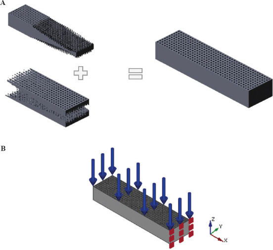
Computer-aided design models of the actuators (A) two-material three-dimensional printing, (B) mechanical forces and boundary constraints.
2.1 Sensitivity analysis
Direct objectives, such as stresses and strains, could be used to determine sensitivities. The strain compliance change with respect to the improved variant,  , is opted as the most common approach[25,26]. A combination of both solid and distributed material models is used for the determination of the sensitivities[27]. The strain energy of the element can be used when the element size does not have a significant effect on the magnitude of the local strain energy. The strain energy density,
  , is calculated as an appropriate objective function for each element, e, to optimize uneven structured meshes as follows:

Where, K and u are the stiffness matrix and the node displacement vectors over the field design, Ω, which is transferred into N discrete elemental counterparts. Defining continuous design variables 0 <ρe <1, the design domain, Ω. By applying a power law, interpolation and information of the material properties, E1 and E2, a single element Young’s modulus, Ee, could be described as follows[28]:

Furthermore, the elemental stiffness matrix, Ke for two materials then could be derived as follows:

Where, K0,e is a single elemental stiffness matrix for a unit solid material. The strain energy density of each element with the volume Ve and the node displacement ue could be obtained as follows:

By differentiating the element-wise strain energy with respect to the normalized element density ρe appropriate sensitivities for a particular element can calculated as follows[27,29,30]:

Applying the system equation Ku = f to a single element considering the design variable yields the following partial differential form:

Since the external load does not depend on the density values, Equation (6) yields:

Accordingly, Equation (7) can be rearranged to:

Transposing Equation (8) leads to:

Using the symmetric stiffness matrix, Equation (9) can be expressed as follows:

Inserting Equations (10) and (9) into Equation (5), the strain energy density sensitivity becomes:

which simplifies to:

Differentiation of the material law, Equation (2) results in:

Having obtained ue by solving the system of equations with a distributed density and material properties[25,27], and inserting Equation (13) in Equation (12), the sensitivity could be determined:

2.2 Sensitivity filtering
The checkerboard structure issue caused by direct use of the selected sensitivities was sorted out using higher order elements, despite longer calculation time. Sensitivity filtering is utilized by applying an increased limit to the checkerboard structure and smoother contours, as shown in Figure 2[26]. Using this approach resulted in poorly defined contours instead of checkerboard patterns. Digital pixel structures are adapted to the finite element mesh to allow the image processing results to be directly applied to TO problem[31,32].
Figure 2.
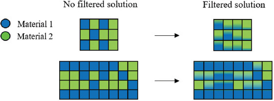
Schematics of two-material topology optimization filtering.
As shown in the flowchart of TO algorithm in Figure 3, the SIMP method was implemented to solve the optimization, in which design variables are defined based on the densities of the discretized elements[33-35]. The mechanical loadings and constraints of the optimization problem were modeled through loading and boundary conditions, as shown in Figure l. The aim is to maximize the deflection of the actuator by optimization of the configuration of the printed layers. The optimization problem is solved iteratively by incorporating the sensitivity guidance. Subsequently, a volume constraint is set to minimize the structural stiffness of the actuator and ensure the convergence of the algorithm[36]. In addition, a standard method of moving asymptotes was employed for each material density to conform to the volume constraint imposed into the optimization.
Figure 3.
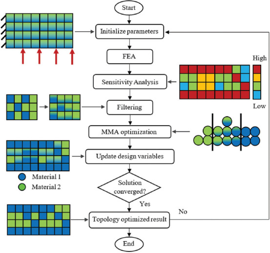
Two-material topology optimization algorithm utilized in this study.
The equivalent optimal solution for 3D printing of two-material configuration at actuator layers is illustrated in Figure 4 where the volume fraction constraint is applied using two different materials for each layer. The results of optimization with respect to volume fraction and objective function over a number of iterations are presented in Figure 5. These results demonstrate the graduate decrease of the objective function with increasing number of iterations until reaching a minimum at iteration 19 when the volume fraction criterion is fulfilled.
Figure 4.
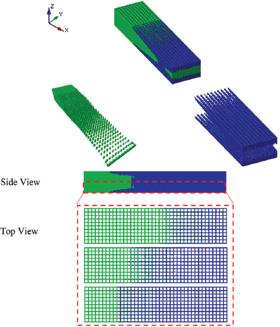
Two-material topology optimization layers’ configuration of bioprinted actuator.
Figure 5.
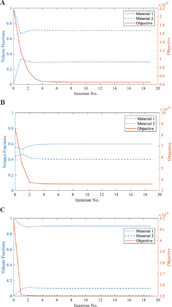
Objective and volume fraction results over iterations at different layers with the constant total volume fraction (A) layer 1; B) layer 2; and (C) layer 3.
3 Fabrication of the 3D bioprinted actuator
3D bioprinting fabrication of hydrogel-based soft actuators requires determination of accurate process parameters to achieve timely coagulation of the extruded strand from the printer nozzle. The previous studies have utilized various synthesis techniques, such as using cross-linking agents or using high-molecular-weight polymer inks, to preserve the structural integrity of the 3D-printed hydrogels on extrusion[37]. Wet spinning and solvent casting are other common methods of 3D-printed hydrogel extrudate solidification[38].
In this paper, however, the liquid hardening method was applied to chitosan hydrogel[22]. The TO algorithm is exported to an EnvisionTEC GmbH Bioplotter. A mixture of chitosan (Sigma-Aldrich, Australia) and acetic acid solution poured into the bioplotter syringe. The hardening of the extruded strand was carried out in 0.25 M sodium hydroxide solution. The statistical significance of the 3D printing procedure for developing chitosan actuators has already been developed and can be accessed in earlier works[22,39]. The two-material bioprinted actuator is shown in Figure 6. 3D-printed hydrogel pastes were made with different molecular weights and concentrations to function as two different materials with varying density and modulus properties so that the different configurations of them could be optimized. The 3D printing hydrogel pastes for the TO actuator were made with variable density and Young’s moduli with ratios of  and
and  respectively. All the samples are 3D printed in same size of 25 mm ×5 mm × 1.5 mm. The volume fractions of the materials 1 and 2 are printed as follows: 31%, 59%, and 91% of material 1 and 69%, 41%, and 9% of material 2 in three subsequent layers.
Figure 6.
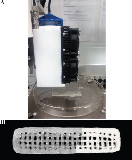
(A) Three-dimensional bioprinting; (B) two-material topology optimized bioprinted actuators.
The average density of triplet 3D-printed actuator samples was measured using an electronic Qualitest Densimeter - SD-200L as 0.72 ± 0.06 g/cm3, 1.12 ± 0.14 g/cm3, and 0.81 ± 0.09 g/cm3 for materials 1, 2, and multimaterial specimens, respectively. The average modulus of the three actuators made from material 1, 2, and multimaterial was measured as 6.8 ± 0.74 MPa, 71 ± 2.91 MPa, and 31.07 ± 5.44 MPa, respectively.
4 Results and discussion
The efficiency of the two-material TO for the improvement of the performance of the bioprinted actuator was demonstrated through a series of experiments. A bending index incorporating the initial length of the actuator (L) as well as X and Y coordinates of the actuator tip is defined, as shown in Figure 7A. The X and Y points are recorded with a webcam (Logitech C920) mounted on a custom-made scaffold, as shown in Figure 7B. The experiment and the computational tool were implemented in MATLAB using a low-cost USB interface Arduino Nano-based driver hardware and a motor driver breakout board for the input voltage modulation. The recorded images were processed through several steps for measuring the X and Y value[40]. The calibration of camera for bending measurement in this study was carried out using the checkerboard method while features of the webcam were obtained by utilizing the Camera Calibration Toolbox in MATLAB to minimize the reprojection error as mean pixel error of 2.07[41]. The measurement set up including a signal generator, two stainless steel electrodes were immersed in 0.2 M NaOH electrolyte solution. A paper clip was used to fix one end of the soft actuator in the electrolyte solution, letting the planar bending of the endpoint occur due to osmotic pressure caused by input signal applied on electrodes.
Figure 7.
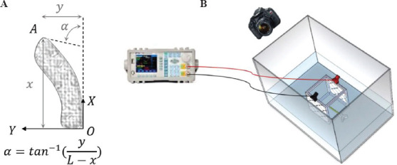
(A) Bending index of the actuator and (B) the measurement set up.
The actuator’s hysteresis behavior was investigated through cyclic “ON-OFF” input signals. A cyclic signal of ±8 V amplitude was applied to the electrodes and the average of three repeated experiments on the bioprinted actuators made entirely of material 1 and material 2 is shown in Figure 8. The results revealed the hysteresis behavior of the actuators over the time of the applied signal with differences mainly observed in the peak magnitudes. It is evident that with repeating cycles the polyelectrolyte actuator’s functionality plunges. The actuator absorbs the moisture and causes swelling, giving rise to large dilatational strains in the plastic region. The semi-crystalline nature of the actuator has an influence on its degradation behavior over bending cycles. Different concentrations of chitosan content lead to different crystallinity which is thought to affect the hysteresis behavior of the actuator by changing its modulus[42]. The deviation of up to 30% from maximum endpoint deflection in the subsequent cycle is observed by means of peak envelop lines, as shown in Figure 8. Further experiments were conducted to compare the bending behavior of the two-material topology-optimized actuator with entirely one material actuator. The results proved the performance improvement of the two-material TO soft actuator compared to the entirely bioprinted one, as shown in Figures 9 and 10. Looking at the details of Figure 10, it can be seen that the two-material TO bioprinted actuator exhibited larger bending compared to the bioprinted material 2 lattice during the actuation process. Accordingly, when the input signal was turned off the bending relaxation of the topology-optimized actuator took placed at 0.022 rad/s which is greater than that shown by the material 2 bioprinted soft actuator at 0.013 rad/s with the same volume fraction but lighter structure. Due to this reason and vastly voltage driven model of the polyelectrolyte actuator, the deflections of both actuators at the completion of cycle are quite alike. However, TO bioprinted actuator always outpaced the non-optimized one at all the tests during the voltage “ON” interval.
Figure 8.
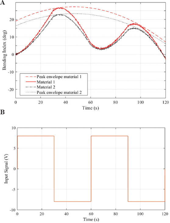
(A and B) Experimental results of three-dimensional-printed actuators entirely made of material 1 and material 2 under cyclic input signal of 8 V.
Figure 9.
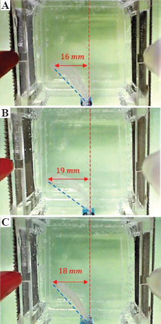
A schematic comparison of bioprinted actuators end point after 40 s; (A) material 2; (B) material 1; (C) two-material topology optimized.
Figure 10.
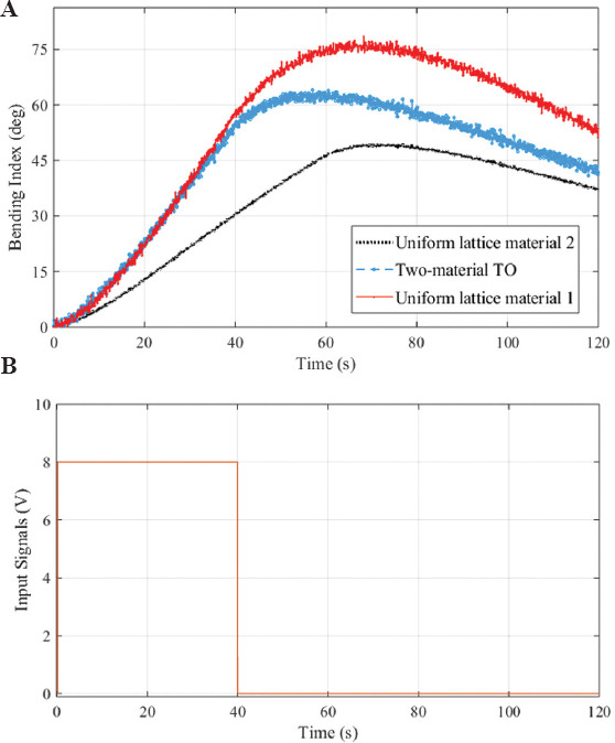
(A and B) Deflection of bioprinted actuators under 8 V input signal. The standard deviations of the average triplet sample results were calculated as 3.21°, 2.88°, and 2.49° for material 1, two-material topology optimization, and material 2 actuators.
The bending of the 3D-printed polyelectrolyte actuators could be determined based on the Donnan equilibrium theory[43], osmotic pressure difference Δπ between both sides of the polyelectrolyte actuator according to a formula developed by Shiga[16,44], in which the osmotic pressure difference Δπ was equal to the maximum tensile stress σ as follows: 
where, E is the elastic modulus, Y the bending deflection, D the thickness, and L length of the actuator prior to bending. Therefore, when the dimensions (D, L, E) are constant, the larger osmotic pressure difference Δπ results in greater bending deflection.
There are several electroactuation and electrochemical factors contributing to the performance polyelectrolyte actuators. For the polyelectrolyte actuator placed at the center of the electrolytic cell, the bending started as soon as the voltage stimulus applied to the electrodes. It was observed that the time required for the actuator tip to reach its peak varied as per the rigidity of the material and its response to the electrical voltage. In our study, electrochemical effects were not incorporated into the TO algorithm. However, it has already been reported that the electroactivity of the 3D-printed chitosan actuator had an optimum performance in the specific concentration of the NaOH solution. The electroactivity increased with the NaOH concentration to a certain extent, followed by the decline of the osmotic pressure at the interface of the hydrogel actuator due to a phenomenon called shield effect where the ion migration is hindered. Hence, the inflow of water to once side of the actuator decreased leading to a slower rate of swelling and as a consequence smaller bending index.
The electroactivity of the 3D-printed polyelectrolyte actuator increased as the DC voltage increased. Yet, at higher voltages of more than 10 V, the electrochemical reactions intensify leading to significant acceleration of the electrochemically generated ion waves and electrolysis bubbles in the cell. These circumstances require further computational fluid dynamics analysis to be incorporated into the TO algorithm, which is beyond the scope of our study.
The 3D-printed bioactuator developed here is used as an ad hoc to demonstrate the capability of TO for functionality enhancement. The contribution of the TO may be influenced by optimization of synthesis parameters to improve the overall electro-chemo-mechanical performance of the actuator. In other words, the bending amplitude of such actuators could be more substantial when TO is combined with optimized synthesis. The main cause of smaller bending amplitude in our sample is attributed to the characteristic of polyelectrolyte hydrogel actuators that are highly dependent on electrical stimulus and once the input signal is turned off, there is a back relaxation in bending. The lack of 3D printing fidelity for certain extrudate systems may reduce the improvement predicted by TO mainly due to the open loop process of 3D printing. In the current systems, there is no feedback control on the printing process parameters to compensate for uncertainties during 3D printing. The lack of precise control in factors such as ambient temperature, moisture, and instrument vibrations could lead to imperfect representation of the TO model. Further, research in optimizing the 3D printing of stimuli-responsive hydrogels in conjunction with TO could result in significant functionality enhancement of bioprinted actuators.
5 Conclusion
In this study, TO was introduced to bioprinted soft actuators to boost the mechanical performance of the system in bending. A multimaterial TO actuator was designed and bioprinted to maximize the bending performance. It was shown through a series of experiments that the two-material TO improves the bending performance compared to uniformly bioprinted soft actuator due to optimized materials configuration within the stack of layers with constant volume. The results demonstrate the efficacy of multimaterial TO-based design to bring about the full potential of the performance of bioprinted soft actuators.
References
- 1.Cohen E, Trimmer BA, Vikas V, et al. American Society of Mechanical Engineers. New York: 2015. Design Methodologies for Soft-Material Robots Through Additive Manufacturing, From Prototyping to Locomotion in ASME 2015 International Design Engineering Technical Conferences and Computers and Information in Engineering Conference. DOI:10.1115/detc2015-47507. [Google Scholar]
- 2.Bodaghi M, Damanpack A, Liao W. Adaptive Metamaterials by Functionally Graded 4D Printing. Mater Des. 2017;135:26–36. DOI:10.1016/j.matdes.2017.08.069. [Google Scholar]
- 3.Choong YY, Maleksaeedi S, Eng H, et al. High Speed 4D Printing of Shape Memory Polymers with Nanosilica. Appl Mater Today. 2020;18(100515) DOI:10.1016/j.apmt.2019.100515. [Google Scholar]
- 4.Zolfagharian A, Khoo S, Kouzani A, et al. Evolution of 3D Printed Soft Actuators. J Sens Actuators A Physical. 2016;250:258–72. DOI:10.1016/j.sna.2016.09.028. [Google Scholar]
- 5.Bodaghi M, Zolfagharian A, Serjouei A, et al. Reversible Energy Absorbing Meta-Sandwiches by 4D FDM Printing. Int J Mech Sci. 2020;173:105451. DOI:10.1016/j.ijmecsci.2020.105451. [Google Scholar]
- 6.Maute K, Tkachuk A, Wu J, et al. Level set Topology Optimization of Printed Active Composites. J Mech Des. 2015;137:111402. [Google Scholar]
- 7.Yu C, Jiang J. A Perspective on Using Machine Learning in 3D Bioprinting. Int J Bioprint. 2020;6:95. doi: 10.18063/ijb.v6i1.253. DOI:10.18063/ijb.v6i1.253. [DOI] [PMC free article] [PubMed] [Google Scholar]
- 8.Hamel CM, Roach DJ, Long KN, et al. Machine-learning Based Design of Active Composite Structures for 4D Printing. J Smart Mater Struct. 2019;28:65005. DOI:10.1088/1361-665x/ab1439. [Google Scholar]
- 9.Bodaghi M, Noroozi R, Zolfagharian A, et al. 4D Printing Self-morphing Structures. J Mater. 2019;1353;12 doi: 10.3390/ma12081353. DOI:10.3390/ma12081353. [DOI] [PMC free article] [PubMed] [Google Scholar]
- 10.Zolfagharian A, Kaynak A, Khoo SY, et al. Pattern-driven 4D Printing. J Sens Actuators A Physical. 2018;274:231–43. DOI:10.1016/j.sna.2018.03.034. [Google Scholar]
- 11.Zolfagharian A, Denk M, Bodaghi M, et al. Topology-Optimized 4D Printing of a Soft Actuator. J Acta Mech Solida Sin. 2019;253:1–13. DOI:10.1007/s10338-019-00137-z. [Google Scholar]
- 12.Lee J, Sing S, Yeong W. Bioprinting of Multimaterials with Computer-aided Design/Computer-aided Manufacturing. Int J. 2020;6:47. doi: 10.18063/ijb.v6i1.245. DOI:10.18063/ijb.v6i1.245. [DOI] [PMC free article] [PubMed] [Google Scholar]
- 13.Zhang B, Chrisey DB, Cristescu R, et al. Solvent-based Extrusion 3D Printing for the Fabrication of Tissue Engineering Scaffolds. Int J Bioprint. 2020;6(211) doi: 10.18063/ijb.v6i1.211. DOI:10.18063/ijb.v6i1.211. [DOI] [PMC free article] [PubMed] [Google Scholar]
- 14.Kaynak A, Zolfagharian A. Multidisciplinary Digital Publishing Institute; Switzerland: 2019. Stimuli-Responsive Polymer Systems Recent Manufacturing Techniques and Applications. DOI:10.3390/ma12152380. [DOI] [PMC free article] [PubMed] [Google Scholar]
- 15.Pilate F, Mincheva R, De Winter J, et al. Design of Multistimuli-responsive Shape-memory Polymer Materials by Reactive Extrusion. Chem Mater. 2014;26:5860–7. DOI:10.1021/cm5020543. [Google Scholar]
- 16.Shiga T, Kurauchi T. Deformation of Polyelectrolyte Gels under the Influence of Electric Field. J Appl Polym Sci. 1990;39:2305–20. DOI:10.1002/app1990.070391110. [Google Scholar]
- 17.Li Y, Sun Y, Xiao Y, et al. Electric Field Actuation of tough Electroactive Hydrogels Cross-linked by Functional Triblock Copolymer Micelles. ACS Appl Mater Interfaces. 2016;8:26326–31. doi: 10.1021/acsami.6b08841. DOI:10.1021/acsami.6b08841. [DOI] [PubMed] [Google Scholar]
- 18.Sigmund O, Maute KJ. Optimization, Topology Optimization Approaches. Struct Multidiscip Optim. 2013;48:1031–55. DOI:10.1007/s00158-013-0978-6. [Google Scholar]
- 19.Huang X, Xie YM. Design, Convergent and Mesh-independent Solutions for the bi-directional Evolutionary Structural Optimization Method. Finite Elem Anal Des. 2007;43:1039–49. DOI:10.1016/j.finel.2007.06.006. [Google Scholar]
- 20.van Dijk NP, Maute K, Langelaar M, et al. Level-set Methods for Structural Topology Optimization:A Review. 2013;48:437–72. DOI:10.1007/s00158-013-0912-y. [Google Scholar]
- 21.Bendsøe MP, Sigmund O. Material Interpolation Schemes in Topology Optimization. J Arch Appl Mech. 1999;69:635–54. [Google Scholar]
- 22.Zolfagharian A, Denk Bodaghi M, et al. Polyelectrolyte Soft Actuators:3D Printed Chitosan and Cast Gelatin. J 3D Print Addit Manuf. 2018;5:138–50. DOI:10.1089/3dp.2017.0054. [Google Scholar]
- 23.Yang R, Chen C. Stress-based Topology Optimization. J Struct Optim. 1996;12:98–105. [Google Scholar]
- 24.Hongying Z. Development of Topology Optimized 3D Printed Soft Grippers and Dielectric Soft Sensors, Theses and Dissertations 2018 [Google Scholar]
- 25.Schumacher A. Springer, Berlin: 2013. Mathematische Grundlagen der Optimierung, in Optimierung mechanischer Strukturen; pp. 45–55. DOI:10.1007/978-3-642-34700-9_3. [Google Scholar]
- 26.Harzheim L. Karosseriebautage Hamburg. Springer, Berlin: 2016. Der Natur in die karten geschaut optimierungsverfahren aus dem bereich der bionik; pp. 3–16. DOI:10.1007/978-3-658-14144-8_1. [Google Scholar]
- 27.Huang X, Xie M. John Wiley &Sons; New York: 2010. Evolutionary Topology Optimization of Continuum Structures:Methods and Applications. [Google Scholar]
- 28.Zhang H, Kumar AS, Chen F, et al. Topology Optimized Multimaterial Soft Fingers for Applications on Grippers, Rehabilitation, and Artificial Hands. J IEEE/ASME Trans Mechatron. 2019;24:120–31. DOI:10.1109/tmech.2018.2∤67. [Google Scholar]
- 29.He D, Liu SJ. BESO Method for Topology Optimization of Structures with High Efficiency of Heat Dissipation. Int J Simul Multidiscip Des Optim. 2008;2:43–8. DOI:10.1051/smdo:2008005. [Google Scholar]
- 30.Kim MG, Kim JH, Cho SH. Topology Design Optimization of Heat Conduction Problems Using Adjoint Sensitivity Analysis Method. Adv Mech Eng. 2010;23:683–91. [Google Scholar]
- 31.Gersborg-Hansen A, Bendsøe MP, Sigmund O. Topology Optimization Using the Finite Volume Method. Struct Multidiscipl Optim. 2005;50:523–35. DOI:10.1007/s00158-005-0584-3. [Google Scholar]
- 32.Kaup IA. Rekonstruktion Verrauschter Nichtregelmäßig Abgetasteter Bilddaten. Bachelor Thesis 2018 [Google Scholar]
- 33.Svanberg K. The Method of Moving Asymptotes a New Method for Structural Optimization. 1987;24:359–73. [Google Scholar]
- 34.Wiedemann J. Springer-Verlag; Berlin: 2007. Leichtbau:Elemente und Konstruktion. [Google Scholar]
- 35.Tavakoli R, Mohseni SM. Alternating Active-phase Algorithm for Multimaterial Topology Optimization Problems:A 115-line MATLAB Implementation. Struct Multidiscip Optim. 2014;49:621–42. DOI:10.1007/s00158-013-0999-1. [Google Scholar]
- 36.Zhang H, Wang Y, Cao J, et al. Topology Optimized Design, Fabrication and Evaluation of a Multimaterial Soft Gripper 2018. IEEE International Conference on Soft Robotics (RoboSoft) 2018 DOI:10.1109/robosoft.2018.8405363. [Google Scholar]
- 37.Lee JM, Yeong WY. Design and Printing Strategies in 3D Bioprinting of Cell-Hydrogels:A Review. Adv Healthc Mater. 2016;5:2856–65. doi: 10.1002/adhm.201600435. DOI:10.1002/adhm.201600435. [DOI] [PubMed] [Google Scholar]
- 38.Wu Q, Maire M, Lerouge S, et al. Solvent-cast 3D Printing of Chitosan Hydrogel Scaffolds for Guided Cell Growth. Front. Bioeng. Biotechnol. Conference Abstract:10thWorld Biomaterials Congress. 2016 DOI:10.3389/conf.FBIOE.2016.01.00336. [Google Scholar]
- 39.Zhang J, Allardyce BJ, Rajkhowa R, et al. 3D Printing of Silk Particle-reinforced Chitosan Hydrogel Structures and their Properties. ACS Biomater Sci Eng. 2018;4:3036–46. doi: 10.1021/acsbiomaterials.8b00804. DOI:10.1021/acsbiomaterials.8b00804. [DOI] [PubMed] [Google Scholar]
- 40.Zolfagharian A, Kouzani AZ, Khoo SY, et al. 3D Printed Soft Parallel Actuator. J Smart Mater Struct. 2018;27:45019. DOI:10.1088/1361-665x/aaab29. [Google Scholar]
- 41.Bouguet JY. Camera Calibration Toolbox for Matlab. International Conference on Indoor Positioning and Indoor Navigation 2010 [Google Scholar]
- 42.Choong YY, Maleksaeedi S, Eng H, et al. 4D Printing of High Performance Shape Memory Polymer Using Stereolithography. Mater Des. 2017;126:219–25. DOI:10.1016/j.matdes.2017.04.049. [Google Scholar]
- 43.Donnan FG. The Theory of Membrane Equilibria. Chem Rev. 1924;1:73–90. [Google Scholar]
- 44.Zolfagharian A, Kouzani AZ, Khoo SY, et al. Development and Analysis of a 3D Printed Hydrogel Soft Actuator. J Sen Actuators A Physical. 2017;265:94–101. DOI:10.1016/j.sna.2017.08.038. [Google Scholar]


