Abstract
This paper mainly reviews the designs of electrohydrodynamic (EHD) inkjet printing machine and related applications. The review introduces the features of EHD printing and its possible research directions. Significant progress has been identified in research and development of EHD high-resolution printing as a direct additive manufacturing method, and more effort will be driven to this direction soon. An introduction is given about current trend of additive manufacturing and advantages of EHD inkjet printing. Designs of EHD printing platform and applications of different technologies are discussed. Currently, EHD jet printing is in its infancy stage with several inherent problems to be overcome, such as low yielding rate and limitation of stand-off height. Some potential modifications are proposed to improve printing performance. EHD high-resolution printing has already been applied to precision components for electronics and biotechnology applications. This paper gives a review about the latest research regarding EHD used for high-resolution inkjet printing. A starting base is given to help researchers and students to get a quick overview on the recent development of EHD printing technology.
Keywords: Electrohydrodynamic printing, inkjet printing devices, additive manufacturing
1. Introduction
With the rapid development of modern microelectronic industry and biotechnology, traditional manufacturing methods cannot satisfy the developing needs of these industries due to inherent restrictions. Additive manufacturing, based on localized deposition of material and a layer-by-layer printing process, is able to build customized products in a short time frame and offers significant advantages over traditional manufacturing processes in the area of design freedom and reduction of assembly time and cost. Electrohydrodynamic (EHD) inkjet, also called “e-jet,” printing as a mask-less, non-contact, direct-write, and additive manufacturing process has attracted the remarkable attention. EHD inkjet printing is first proposed as a solution to the limited resolution of the conventional inkjet printer system since EHD printing can produce a thin and intact jet without the need to miniaturize the nozzle. The process involved, called “electrospray in the cone-jet mode,” uses electrical (“Maxwell”) forces to pull the liquids from the nozzle tip, rather than apply thermal or acoustic energy to push liquid from a fine capillary. In the liquid cone, the electric field causes electric charges to accumulate at the liquid surface. The electrical forces counteract surface tension, and the resultant force leads the meniscus at the nozzle end to change from a hemispherical to a conical shape. With the increase of electric field, the electric stress at the tip of cone exceeds the surface tension and a droplet or jet of liquid is emitted toward ground substrate. The EHD inkjet printing can be a high-resolution inkjet printing technology because there is a large “neck-down ratio” between the diameters of the nozzle and the jet: The jet diameter is about two orders of magnitude smaller than the nozzle diameter. Thus, in EHD jet printing, the nozzle diameter (>100 μm) can be much larger than that used in thermal or piezoelectric inkjet printing (about 20 μm); this makes blockages much less likely and makes it easy to employ a highly viscous liquid[1]. It is used in the field of micro- or nano-manufacturing for patterning of a large class of materials on a variety of substrates without adversely affecting the chemical properties of the deposited materials. This paper is organized as follows. We describe different types of EHD printing machines designed on the basis of fundamental EHD mechanisms. The ensuing section discusses about the application of EHD inkjet printing in different fields of research.
2. EHD Inkjet Printing Machines and Control
An EHD inkjet printing system usually consists of a fluid supply system, linear/rotary motorized or manual positioners, a high voltage power supply, and visualizing and imaging devices[2]. The fluid supply system delivers liquid ink through a pipeline to the tip of the nozzle at the desired flow rate. The supply system can be a syringe or vacuum pump[3] or a liquid reservoir with a constant liquid height[4,5]. The dispensing nozzle (usually made from stainless steel) is compatible with interchangeable syringe and can be purchased from commercial companies. The tiny size of nozzle (smaller than 50 μm) can be fabricated by pulling glass pipettes or borosilicate capillaries and the tip of nozzle is coated by a thin layer of metal. To prevent wetting of the ink and obtain a large contacting angle at the nozzle outlet, metal nozzles are usually processed by chemical agents. The nozzle is grounded while a high negative potential is applied to the substrate and this prevents charge accumulation and potential shock hazards during the operation of the pumping system[6]. The gap between the nozzle tip and the substrate, known as standoff height, is critical for stable printing. Thus, it is necessary to use a high precision motorized stage to adjust standoff height. A high DC voltage power source is employed to produce a strong electric field to deform the liquid meniscus, and a function or pulse generator is used to facilitate drop-on-demand printing. To supply voltage and ink material to multiple nozzles separately, a voltage distributor and a multichannel syringe pump are necessary[7]. Since the decay rate of residual charges on droplets is slow on the insulating substrates, the residual charge of droplets deposited onto a substrate will change the electrostatic field distribution and may interrupt the subsequent printing behavior[8]. Park et al. used a sinusoidal ac voltage to switch the charge polarity of droplets[8] and charges in the subsequent droplet to neutralize charges in the previous droplet. A visualization system includes a high-speed charge-coupled device camera, a microscopic zoom lens system, and an illumination source. Since the timescale for the most relevant EHD phenomena is very short (less than a microsecond), a conventional continuous-illumination source will cause blurring images by overexposure of jet motion. Thus, a high-speed shutter system or a short duration flash with an open shutter is suitable for high-speed events. The external disturbances, such as vibration coming from the building, may be damped by vibrational isolation platform. These attributes often lead to demands for careful control and optimization for each ink material. Table 1 summarizes the optional devices for each subsystem of EHD print.
Table 1.
Functions of each working device in different EHD printing platforms
| Names of EHD printing subsystems | Optional devices | Function |
|---|---|---|
| Fluid supply | Syringe pump/vacuum pump/liquid reservoir, pipeline and connector | Delivering ink to the tip of printing nozzle |
| Positioner | Linear/rotary motorized positioner/manual positioner | Transmitting nozzle to printing position accurately; adjusting distance between two electrodes |
| Power supply | High voltage DC/AC power supply (up to 10 kV) | Providing strong electric field to produce stable conejet |
| Visualizing and imaging device | Highspeed CCD camera, Microscopic zoom lens, LED light | Observing deformation of cone and highspeed emission of droplet |
| Vibration isolation platform | Mechanical vibration isolation platform/optical tables | Preventing vibration from effecting printing results |
Park demonstrated that a nozzle with a diameter of 50 μm can create dot diameter not <20 μm in graphic arts. In addition, they developed an EHD inkjet printing system as shown in Figure 1a and a droplet with submicrometer size was able to be produced by a microcapillary with a diameter from 0.3 to 30 μm[9]. The resulting high resolution is partially attributed to a fine nozzle with sharp tips. Another reason is that small distance between nozzle and substrate shown in Figure 1b can minimize lateral variations in the placement of droplets. Furthermore, breakup occurring in electrospray can be avoided at such short distance[5], and a sharp corner is also benefited from a small gap. Fluid is propelled through a glass capillary by a syringe pump. A high-speed camera with 66,000 frames per second was used to observe the dynamics of EHD jetting, and both pulsating and stable jet modes are captured by imaging devices. Park et al. used a solution of a conducting polymer ink to electrohydrodynamically print high-resolution patterns with 10 μm droplet diameter[9], as shown in Figure 1c. Figure 1d shows EHD printing results of silicon nanoparticles and single crystal Si rods dispersed in 1-octanol[9].
Figure 1.
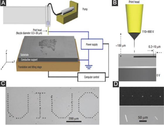
(A) A layout of e-jet printing system. (B) Configuration of the nozzle electrode and substrate electrode. A small diameter of gold-coated nozzle with sharp tip, and a short distance between two electrodes. (C) The average dot diameter of letters printed with the conducting polymer is about 10 μm. (D) The average diameter of Si nanoparticles printed from a suspension in 1-octanol is 3 nm (Adapted from Park et al.[9]).
2.1. Multiple Printing Heads EHD Printing System
Barton built up a desktop EHD inkjet printing system of advantages including compactness, high resolution, and low cost (<50 k USD). Most components of this desktop printer were purchased from vendors. A 5-μm nozzle tip is employed to produce average 2.8 μm diameter droplets; slight discrepancies in droplet placement were observed, caused by natural frequency of the pulsating cone-jet model[10]. Figure 2A shows the overall setup. The flow rate of liquid ink is controlled by a pneumatic pressure regulator, and the value of pressure can be read out from pressure gauge. Similarly, there are X- and Y-axis electronic positioning stages, as well as a manual z-axis and a manual rotary axis included in the moving system. The substrate sits on the substrate mount, and they are held in place by a vacuum chuck. To print different inks, a multiple nozzle holder was designed as shown in Figure 2B and it consists of several individual nozzle holders and a manual rotation mount[10]. The LabVIEW software is used to read encoder position, monitor voltage output repeatedly, and control as well as coordinate voltage and position commands.
Figure 2.
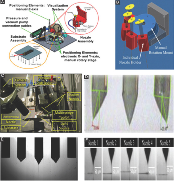
(A) Layout of desktop e-jet system and related hardware. (B) A multinozzle holder (from[10]). (C) An EHD printing system with multiprinting head (adapted from Sutanto et al.[11]). (D) The jetting angle in linear array multinozzle EHD inkjet printing head (Adapted from Choi et al.[12]). (E) End effects in an array of multiple emitters (adapted from Tran et al.[15]). (F) Axisymmetric cone-jets formed at apex of each nozzle (adapted from Khan et al.[7]).
Sutanto et al. designed a multiprint head to print heterogeneous materials, and a tilted rotary mechanism was designed to switch between the active and inactive printing nozzle, as shown in Figure 2C[11]. A pressure distributor was used to control back pressure of each nozzle, and a circuit board is employed to assign voltage signal to active printing unit installed in the print head holder. Since the weight of print heads and their distance from the axis of rotation produce a large rotational inertia, a transmission with a high gear ratio is required to couple with the motor to provide a sufficient large torque[11]. However, the stick-slip resistance coming from the gear reduces the accuracy of overlay in drop-on-demand. To offset this undesired effect, a two-step macro/micro-positioning method is employed to achieve micropositioning accuracy. The function of the macropositioning algorithm is to bring the nozzle into the camera view field, and duty of the micropositioning controller is to apply precise servo level control to locate nozzle position with respect to the substrate[11].
A low flow rate is favorable to the generation of a small jet since the diameter of charged liquid jet depends on flow rate. A multiplexed EHD printing head that can deposit multiple jets simultaneously has been investigated to obtain a high yielding rate for high-resolution printing. In the configuration of the linear array of multinozzles, the meniscus and jets at the end of nozzle are often deflected due to asymmetric electric field and repulsive forces between adjacent jets[12]. Figure 2D shows a jetting angle between the axis of the nozzle and the tip of the cone[12]. Tran compared two methods to alleviate undesired end effects[13]. In the first method, a non-conductive nozzle made of polymethyl methacrylate was fabricated, and in the second method, two dummy capillary nozzles located at both sides of the array were used. Both methods can dramatically minimize end effects, supported both by simulation of electric field and by experiments. Lee used MEMS method to fabricate three single nozzles in a base that is made of silicon and applied a conductive material on the surface of silicon base at the side of nozzle outlet[14]. The asymmetric cones are observed because of end effect in the pin-shaped nozzle array. However, the end effect is not detected in the silicon-based multinozzle structure. Si et al.[15] used two dummy nozzles at the left- and right-most side in an array of five capillaries to reduce end effects. Figure 2E shows that two nozzles next to middle nozzle still experienced asymmetric emission, and this is caused by the effect of the meniscus tip. Khan et al. used a numerical method to investigate the magnitude of the electric field strength around the tip of multinozzles to optimize the distance between nozzles[16]. Axisymmetric cone-jets were formed at the tip of each nozzle in Figure 2F. As multiple pin-shaped nozzles are arrayed, the onset voltage is changed with the distance of operating nozzles due to interference and distortion in the electric field[17].
Choi et al. used three glass nozzles with independent voltage connection and ink supply source to explore that interaction (cross-talking) between the charged neighboring jets in the electric field[12]. As a result, the interaction of electric fields among multiple nozzles is reduced by taking a triangular array of nozzles instead of a traditional linear array of nozzles[12]. The end effect between the neighboring jets reduces with a decrease of nozzle diameter. However, the smaller diameter of the nozzle may cause a risk of nozzle blockage[7].
2.2. Nozzle-ring Electrode Configuration
A nozzle-ring electrode configuration is designed to integrate the nozzle and ground electrode to eliminate the disturbance due to the surface irregularity of the substrate, to enable printing on a non-conductive surface, and to overcome restriction of standoff distance. As shown in Figure 3, A single nozzle-ring electrode was employed to investigate the formation of organic solvent jet[18]. Kim compared onset voltage of two types of electrodes (plane- and hole-type) by adjusting different processing parameters, including diameter of glass capillary nozzle, hydrostatic back pressure head in the reservoir, and standoff height[19]. When other processing parameters are maintained the same, onset jetting voltage for hole-type electrode is larger than that for plane-type electrode since the less surface area of electrode in the previous type. However, when the gap distance was larger than 200 μm, the onset jetting voltage was insensitive to the change of hole diameter[19]. The assumption that onset radius of curvature is not affected by the whole distribution of electric field for the same nozzle seems reasonable from simulation results[19]. Thus, value of onset electric field at the meniscus did not change with either diameter of hole or gap distance[19].
Figure 3.
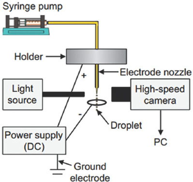
Schematic of nozzle-ring electrode configuration (adapted from Zhang et al.[18]).
Lee et al. used a ring-shaped gate electrode to suppress intact jet from generating satellite droplets or spraying[20]. A maximal suppression was obtained as the inner diameter of ring electrode is 5 times bigger than the outer diameter of nozzle, and the gap distance between nozzle tip and gate electrode is 2½ times as big as the outer diameter of nozzle[20]. Tse developed a double layer electric field shaping print head to obtain smaller size of droplets compared to results from single layer field shaping print head[21]. To maintain constant operating conditions, Barton et al. investigated a two degree of freedom control algorithm[21]. They used an iterative learning control algorithm and a feedback controller to obtain feedforward control signal. The feedforward voltage signal is applied to compensate for repeatable changes, such as standoff height, and feedback component is employed for uncertainty in jetting operating conditions[22]. Table 2 lists some optional solutions for problems that usually appear in EHD printing process.
Table 2.
Some corresponding solutions for possible problems in EHD 3D printing
| Existed problems | Alternative solutions | |
|---|---|---|
| Reducing the size of droplet | For large conductivity (≥10−4 S/m) | Reducing flow rate, increasing voltage |
| For small conductivity (<10−4 S/m) | Reducing flow rate, minimizing diameter of nozzle outlet | |
| Increasing precision of placement | Keeping a small distance between nozzle and substrate | |
| Increasing yielding rate | Increasing numbers of nozzle | |
| Alleviating end effects from neighboring nozzle | Inserting nonconductive/dummy nozzles; inserting metal nozzles into nonconductive materialbased multinozzle structure; increasing distance between neighboring nozzle; changing the shape of nozzle array | |
| Eliminating disturbance due to surface irregularity of the substrate, such as uneven surface, restriction of standoff distance, nonconductive material | Changing configuration of electrodes, such as nozzlering type; applying sinusoidal AC voltage and print droplet whose charge alternates between positive and negative charges | |
4. Applications of EHD Inkjet Printing
EHD printing is developed as a cost-effective inkjet printing process with high resolution. With EHD printing, functional materials can be selectively and precisely printed on desired substrates. Applications of EHD in different industries have been summarized by other authors[23,24]. This review only introduces three-dimensional (3D) printing that we are interested, and applications of two-dimensional (2D) printing are reviewed for comparison reasons. Most EHD printing applications have been focused on 2D printing, and only a few research groups have explored 3D printing techniques that are restricted by several issues discussed in previous sections. The following sections review the representative results of both 2D and 3D printings.
3.1. Applications of EHD 2D Printing
3.1.1 Electronics Applications
EHD inkjet printing is an attractive fabrication method for microscale electronic devices since this method can obtain features with fine resolution and it is compatible with a series of functional inks. The rest of this section introduces several applications of EHD printing in fabrication of electronic components. As an example, Park et al. used EHD method to print photocurable polyurethane (PU) precursor as a resist layer for patterning metal electrodes by chemical etching[9]. The printing results are shown in Figure 4A and B.
Figure 4.
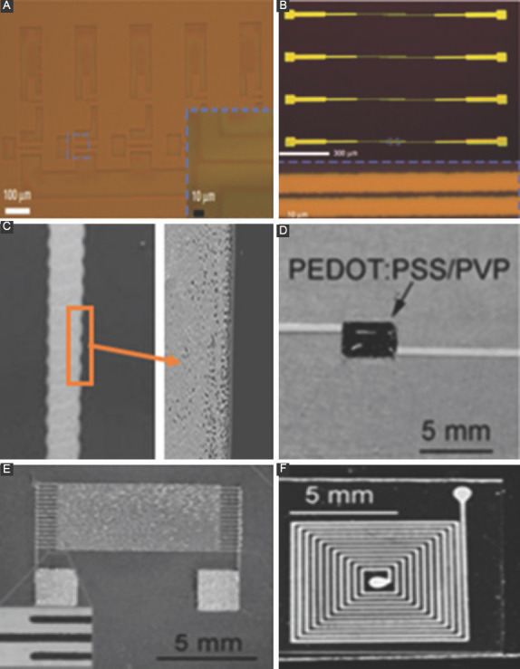
(A) Polyurethane etch resist for a circuit is printed by electrohydrodynamic (EHD) before etching the metal layer. (B) EHD printed array of source or drain electrode pairs after deposition of resist layer, etching of metal, and stripping the resist (adapted from Park et al.[9]). (C) Surface morphology of the edge of the silver tracks scanned by scanning electron microscope at a magnification of ×5000 (adapted from Wang et al.). (D) A printed coated resistor. (E) A printed interdigitated capacitor. (F) A printed spiral inductor (adapted from Wang et al.[30]).
Metallo-organic compound solutions and inks formulated from metal nanoparticle suspension are two main kinds of ink for printing metallic patterns. The former ink is a true solution where the metal salt is fully dissolved in the solvent and this property decreases sediments and clogging issues arising from nanoparticles in the suspension[25]. An uniform silver microtracks with a 35-μm line width was printed by Wang et al., and its resistivity was measured to be within a range of (2–4)×10−8 Ωm, which is 2.4 times of the theoretical value of bulk silver (1.6 × 10⁻⁸ Ωm)[25,26]. As shown in Figure 4C, the edge of micro track is more porous compared to central part, since repulsive interaction between the charged droplets leads to an incompletely suppressed jet breakup. Sutanto et al. successfully fabricated a crossover intersecting structure using a multimaterial e-jet printing system to deposit conductive lines, which was made of an organic silver ink without any particle structure, on the substrate, and a photo-curable polymer droplet was printed at two intersecting conductive lines as isolating points[11].
The latter material, which is a liquid ink containing metal nanoparticles, is usually directly deposited on the substrate; then, heating the metal nanoparticles makes them connect to each other. Heating process helps those particles to remove cover and form a continuous dense metal structures. EHD inkjet printing is able to print conductive lines for metallization in printed circuit boards and backplanes of printable transistors[27]. Since noble nanoparticles, such as gold and silver, have good electrical conductivity and non-oxidizing properties, their colloidal solution is firstly applied in the application of electronics. Khan et al. used a multinozzle to print three parallel conductive lines made out of colloidal solution containing silver particles and the width of line is about 140 μm. After sintering at 250°C for 1 h at a constant heating rate of 2°C/min, the resistivity of silver line is 5.05 × 10⁻⁸ Ω m, 3 times higher than the resistivity of bulk silver[16]. Prasetyo et al. found that diameters of Ag dots can be reduced on a hydrophobic surface coated with octadecyltrichlorosilane (OTS), due to lower surface energy. A hydrophobic substrate with OTS coating can also overcome the existence of the coffee-stain effect[28]. Youn showed that the width of minimum silver line is about 5.8 μm using a tilted nozzle[29]. Wang succeeded in printing several passive electrical components, such as coated resistors, interdigitated capacitors, and spiral inductors as shown in Figure 4D-F and the minimum line width about 60 μm is achieved using a 110 μm nozzle[30]. Khalid deposited silver patterns on thick glass substrates and found that the diameter of droplet after the sintering process is around 3.6 μm, which is 2.78 times smaller than the internal diameter of nozzle[31]. Kang used EHD to print silver lines within 10 μm wide on a large flexible graphene substrate and the sheet resistance of hybrid electrode is as low as 4 ohm per unit square with 78% optical transmittance[32].
To lower cost and obtain less electromigration effect, colloidal solutions containing copper nanoparticles were tested[7]. As a result, the resistivity of deposited copper track was 5 times as high as resistivity of bulk copper and the difference of resistivity is attributed to relatively porous microstructure of copper track[7]. Rahman et al. applied EHD methods to print a colloidal solution containing copper nanoparticles on a silicon substrate; the range of resistivity of the printed copper tracks was from 5.98 × 10⁻⁸ Ωm to 2.42×10⁻⁷Ωm.[33]. Han et al. used a nozzle with an inner diameter of 160 μm to print molten-metal by an EHD method, and a straight metal line with a diameter of 50 μm was obtained at a plotting speed of 1 mm/s[34].
3.1.2 Biotechnology Applications
Inkjet printing had been previously employed to process living cells[35], but the processing of concentrated biosuspensions has been severely limited by cellular loading and this has resulted in the formation of rather coarse structures[36]. Jayasinghe et al. for the first time used electric field-driven technology to process and deposit living cells, like Jurkat cell suspension, and human peripheral blood monocytes in suspension. A strong electric field was created between nozzle and ring-shaped ground electrode and polydisperse distribution of droplets, indicating that an unstable mode of jetting was observed. This can be attributed to high electric conductivity and relatively low viscosity of solution[36]. As a result, no adverse effects on either cellular structure or basic activities of living cells, such as cellular damage and irregular rate of division, had been found[36]. To generate a near-mono distribution of cell-bearing droplets in stable jetting conditions, Kwok et al. reported a hybrid processing approach by combining bio-electrosprays and aerodynamically assisted bio-jetting and jetted cells exhibited all expected cellular behavior[37].
Although electrospray is able to produce relatively smaller droplets, electrospray cannot emit single microscale droplet on substrate, and sometimes, patterns have broad and non-uniform size distribution. EHD high-resolution technique allows to print a controlled droplet size and deposit at desired locations. Park et al. patterned large areas of DNA inks with complex configuration and feature size with resolutions on the order of 100 nm[38]. Properties of DNA were not adversely affected by this printing process. As shown in Figure 5A, a pattern of butterfly was deposited at an inherent frequency when the nozzle scan over the substrate and the positions of individual droplets are not well controlled[38]. In Figure 5B, a 14 × 14 arrays of the DNA dots were deposited by drop-on-demand e-jet printing method; the driving voltage was turned on and off on demand and it offered excellent control over the placement of individual droplets at expense of printing speed[38].
Figure 5.
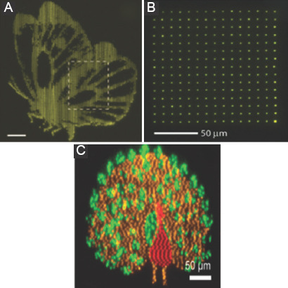
Dot diameter is 2 μm (a) butterfly pattern in fluorescence micrographs. (b) 14 × 14 DNA arrays in fluorescence micrograph printed in drop-on-demand mode (adapted from Park et al.[38]). (c) Fluorescence microscope images of a peacock pattern formed using different fluorescently proteins (adapted from Shigeta et al.[39]).
Sutanto et al. used two biological materials to print droplets whose size is about 2 μm on average, and yellow color dots at right bottom corner are formed by overlaying two ink dots[11]. It can be considered as a proof to demonstrate registration accuracy of the droplet diameter is within 2 μm[11]. Shigeta et al. used multinozzle EHD inkjet printing system to create micro- and nano-scale patterns of proteins on flat silica substrates. A structured plasmonic analysis is shown in Figure 5C and the study showed that the printing process does not adversely alter the protein structure or function[39].
3.2. EHD 3D Printing
3.2.1 Electronics Applications
In Figure 6A, Wang et al. used silver ink to deposit five overlapping drops of 88 μm size by a single-layered printing[40]. Figure 6B indicates that droplets were mainly accumulated vertically rather than spreading laterally by three-layered printing and a denser morphology was obtained compared to porous structures built by single-layered printing[40]. Previously, EHD jet printing has been applied to the fabrication of devices on a 2D flat substrate. Seong et al. succeeded in printing lines with a width of 7 μm and height of 1.43 μm on a 3D-curved surface with curvature, diameter, and height of 5.5 m−1, 60 mm, and 10 mm, respectively, as shown in Figure 6C. The resulting sheet resistance is below 1.5 Ω[41].
Figure 6.
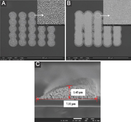
(A) Five stripes and each stripe built by single-layered printing. (B) Each stripe built by three-layered printing (adapted from Wang and Stark[40]). (C) Field emission scanning electron microscope cross-sectional image of electrohydrodynamic jet-printed Ag mesh on the surface (adapted from Seong et al.[33]).
3.2.2 Biotechnology Applications
Sullivan et al. presented three ground electrode geometries and they were the ring-shaped electrode, a plate shaped electrode and a point-shaped electrode. The ring-shaped and a plate shaped electrode produced a cone-shaped spray diverging droplets, while the point-shaped electrode focus the spray on a point. They employed the point-shaped electrode to create a self-supporting arch between two adjacent vertical wall or pillar structures[42]. In addition, they were able to build a three-dimensional structure by using the same electrode geometry and this structure is biocompatible [42].
Ahmad et al. utilized a controlled 3D writing method by decreasing deposition distance to build ordered and complex structures[43]. In Figure 7A and b, an overlapped and orientated 3D grid pattern was printed using a pure PU polymer solution which is widely used as a biomaterial for blood contact applications[43].
Figure 7.
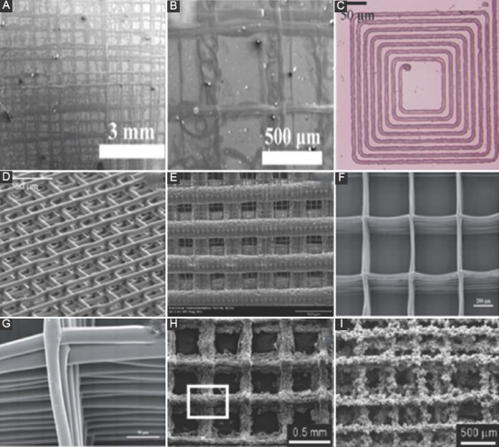
(A) Multilayered ordered complex structure of polyurethane. (B) Close-up view of (c) (adapted from Ahmad et al.[1]). (C) Spiral-in circle two-dimensional (2D) pattern fabricated by electrohydrodynamic (EHD) jet printing of melted polycaprolactone (PCL). (D) 3D scaffold structures fabricated by EHD jet plotting of melted PCL. (E) Scanning electron microscope (SEM) images of the hierarchical 3D scaffold structures (adapted from Wei and Dong[44]) and (G) Surface topography of PCL structure built by EHD printing method (adapted from Cai et al.[46]). (H) 3D scaffold fabricated by a normal EHD-printing without cushioning bath in SEM micrographs. (I) The highly roughened surface morphology of the EHD-plotted 2D scaffold on the PEO solution bath (adapted from Ahn et al.[47]).
The control of layer-by-layer scaffold structure mentioned above was poor, and thus, researchers explored a precision controlled deposition method to fabricate 3D structures with controlled fiber diameter, orientation, and pore size. Particularly, Wei et al. applied a hybrid hierarchical approach to fabricate 3D scaffolds using polycaprolactone (PCL), a phase-change, biocompatible, and biodegradable printing material. Melting extrusion was employed under pneumatic pressure to produce a filament of hundreds of microns in diameter, and EHD jetting was used to deposit small feature with single micron resolution. Both 2D and 3D patterns were fabricated as shown in Figure 7C-E[44,45]. Cai et al. used a similar EHD direct writing technique to build a 3D PCL scaffold with controlled fiber diameter and orientation [Figure 7F and G], and collagen was grafted to scaffold to improve regeneration of cartilage[46]. Collagen-grafted scaffold helps chondrocytes to maintain healthy phenotypes, and it also increases production of cartilage-like extracellular matrices, when compared with conventional PCL scaffolds[46].
Ahn et al. used the EHD printing method to fabricate a 3D porous structure, and the result showed that biological capabilities of scaffolds benefit from roughened surface and enhanced water absorptivity[47]. Instead of traditional substrates, a polyethylene oxide (PEO) solution bath was used as a ground target to provide an elastically cushion to prevent plotted struts crumbling, as shown in Figure 7H and i. In addition, a grounded copper plate was immersed in the PEO bath, and previously deposited layers of struts can be dissolved in the remnant solvents to eliminate residue charges[47].
4. Conclusion
EHD phenomenon has been known for more than a century, while EHD technology was just applied as a high-resolution additive manufacturing method a decade ago. EHD inkjet printing utilizes a unique cone-jet phenomenon to obtain a thin liquid jet without nozzle blockage as commonly experienced by conventional inkjet printing. It is necessary to keep cone-jet in stable operating regime to achieve the goal of high resolution. Many functional materials have been directly deposited on a variety of substrates by EHD deposition in different industrial areas, such as rapid prototyping, electronics, and biotechnology. However, low production rate of EHD inkjet printing is a main drawback that impedes widespread applications. This is, especially, a concern when small diameter jets are required for high-resolution printing. Although a multinozzle printing head is considered as a remedy to this problem, unstable jets may appear in this circumstance because of an asymmetric electric field arising from neighboring nozzles. Researchers developed different methods to alleviate the interaction of adjacent jets. In addition, a nozzle-ring electrode is proposed to improve the performance of EHD printing in 3D printing applications.
Acknowledgments
This work was partially supported by the [NSF] under Grant [number 1437798]; and [NSF] under Grant [Number 1538318]. The authors would like to thank Dr. Richard Forbes who provided important suggestions on revision, and we appreciated his support and help.
References
- 1.Ramos A, Chen C H. Electrokinetics and Electrohydrodynamics in Microsystems. Springer, Verlag Wien: 2011. Electrohydrodynamic stability; pp. 177–220. http://doi.org/10.1039/b906909g. [Google Scholar]
- 2.Raje P V, Murmu NC. A review on electrohydrodynamic - Inkjet printing technology. Int J Emerg Technol Adv Eng. 2014;4(5):174–183. [Google Scholar]
- 3.Park S E, Kim S, Lee D, et al. Fabrication of silver nanowire transparent electrodes using electrohydrodynamic spray deposition for flexible organic solar cells. J Mater Chem A. 2013;1(45):14286–14293. https://doi.org/10.1039/c3ta13204h. [Google Scholar]
- 4.Yogi O, Kawakami T, Yamauchi M, et al. On–demand droplet spotter for preparing pico-to femtoliter droplets on surfaces. Anal Chem. 2001;73:1896–1902. doi: 10.1021/ac0012039. https://doi.org/10.1021/ac0012039. [DOI] [PubMed] [Google Scholar]
- 5.Chen C H, Saville DA, Aksay IA. Scaling laws for pulsed electrohydrodynamic drop formation. Appl Phys Lett. 2006;89(12):1241031–1241033. https://doi.org/10.1063/1.2356891. [Google Scholar]
- 6.Poon H F. Electrohydrodynamic Printing. PhD Thesis 2002 [Google Scholar]
- 7.Khan A, Rahman K, Kim D, et al. Direct printing of copper conductive micro–tracks by multi–nozzle electrohydrodynamic inkjet printing process. J Mater Process Technol. 2012;212(3):700–706. https://doi.org/10.1016/j.jmatprotec.2011.10.024. [Google Scholar]
- 8.Park J, Hwang J. Fabrication of a flexible Ag–grid transparent electrode using ac based electrohydrodynamic jet printing. J Phys D:Appl Phys. 2014;47(40):4051021–4051027. https://doi.org/10.1088/0022-3727/47/40/405102. [Google Scholar]
- 9.Park J U, Hardy M, Kang SJ, et al. High–resolution electrohydrodynamic jet printing. Nat Mater. 2007;6(10):782–789. doi: 10.1038/nmat1974. https://doi.org/10.1038/nmat1974. [DOI] [PubMed] [Google Scholar]
- 10.Barton K, Mishra S, Shorter K A, et al. A desktop electrohydrodynamic jet printing system. Mechatronics. 2010;20(5):611–616. https://doi.org/10.1016/j.mechatronics.2010.05.004. [Google Scholar]
- 11.Sutanto E, Shigeta K, Kim Y K, et al. A multimaterial electrohydrodynamic jet (E–jet) printing system. J Micromech Microeng. 2012;22(4):4500801–4500811. https://doi.org/10.1088/0960-1317/22/4/045008. [Google Scholar]
- 12.Choi K H, Khan A, Rahman K, et al. 2011a, Effects of nozzles array configuration on cross-talk in multi-nozzle electrohydrodynamic inkjet printing head. J Electrostat. 69(4):380–387. https://doi.org/10.1016/j.elstat.2011.04.017. [Google Scholar]
- 13.Tran S B, Byan D, Nguyen VD, et al. Polymer–based electrospray device with multiple nozzles to minimize end effect phenomenon. J Electrostat. 2010;68(2):138–144. https://doi.org/10.1016/j.elstat.2009.11.011. [Google Scholar]
- 14.Lee J S, Kim S, Kim Y, et al. Design and evaluation of a silicon based multi–nozzle for addressable jetting using a controlled flow rate in electrohydrodynamic jet printing. Appl Phys Lett. 2008;93(24):2431141–2431143. https://doi.org/10.1063/1.3049609. [Google Scholar]
- 15.Tran S B, Byun D, Lee S. Experimental and theoretical study of a cone–jet for an electrospray microthruster considering the interference effect in an array of nozzles. J Aerosol Sci. 2007;38(9):924–934. https://doi.org/10.1016/j.jaerosci.2007.07.003. [Google Scholar]
- 16.Khan A, Rahman K, Hyun M, et al. Multi–nozzle electrohydrodynamic inkjet printing of silver colloidal solution for the fabrication of electrically functional microstructures. Appl Phys A. 2011;104(4):1113–1120. https://doi.org/10.1007/s00339-011-6386-0. [Google Scholar]
- 17.Park H, Kim K, Kim S. Effects of a guard plate on the characteristics of an electrospray in the cone–jet mode. J Aerosol Sci. 2004;35(11):1295–1312. https://doi.org/10.1016/j.jaerosci.2004.05.012. [Google Scholar]
- 18.Zhang X, Isao K, Kunihiko U, et al. Direct observation and characterization of the generation of organic solvent droplets with and without triglyceride oil by electrospraying. Colloids Surf A:Physicochem Eng Asp. 2013;436:937–943. https://doi.org/10.1016/j.colsurfa.2013.07.032. [Google Scholar]
- 19.Kim H, Song J, Chung J, et al. Onset condition of pulsating cone–jet mode of electrohydrodynamic jetting for plane, hole, and pin type electrodes. J Appl Phys. 2010;108(10):10280401–10280410. https://doi.org/10.1063/1.3511685. [Google Scholar]
- 20.Lee S, Kichul A, Sanguk S, et al. Satellite/spray suppression in electrohydrodynamic printing with a gated head. Appl Phys Lett. 2013;103(13):1335061–1335064. https://doi.org/10.1063/1.4822264. 1. [Google Scholar]
- 21.Tse L, Barton K. A field shaping printhead for high–resolution electrohydrodynamic jet printing onto non–conductive and uneven surfaces. Appl Phys Lett. 2014;104(14):1435101–1435104. https://doi.org/10.1063/1.4∇03. [Google Scholar]
- 22.Barton K, Mishra S, Alleyne A, et al. Control of high–resolution electrohydrodynamic jet printing. Contr Eng Pract. 2011;19:1266–1273. https://doi.org/10.1016/j.conengprac.2011.05.009. [Google Scholar]
- 23.Jaworek A, Sobczyk A. Electrospraying route to nanotechnology:An overview. J Electrostat. 2008;66(3–4):197–219. https://doi.org/10.1016/j.elstat.2007.10.001. [Google Scholar]
- 24.Onses M S, Sutanto E, Ferreira PM, et al. Mechanisms, capabilities, and applications of high–resolution electrohydrodynamic jet printing. Small J. 2015;11(34):4237–4266. doi: 10.1002/smll.201500593. https://doi.org/10.1002/smll.201500593;https://doi.org/10.1002/smll.201570209. [DOI] [PubMed] [Google Scholar]
- 25.Wang K, Paine M D, Stark J P W. Freeform fabrication of metallic patterns by unforced electrohydrodynamic jet printing of organic silver ink. J Mater Sci:Mater Electron. 2009a;20(11):1154–1157. https://doi.org/10.1007/s10854-008-9843-6. [Google Scholar]
- 26.Wang K, Paine M D, Stark J P W. Fully voltage–controlled electrohydrodynamic jet printing of conductive silver tracks with a sub–100μm linewidth. J Appl Phys. 2009b;106(2):249071–249074. https://doi.org/10.1063/1.3176952. [Google Scholar]
- 27.Choi K H, Khalid RR, Muhammad NM, et al. Recent Advances in Nanofabrication Techniques and Applications. London, UK: InTech; 2011. Electrohydrodynamic inkjet-micro pattern fabrication for printed electronics application; pp. 547–568. [Google Scholar]
- 28.Prasetyo F D, Yudistira HT, Nguyen VD, et al. Ag dot morphologies printed using electrohydrodynamic (EHD) jet printing based on a drop–on–demand (DOD) operation. J Micromech Microeng. 2013;23(9):9502801–9502810. https://doi.org/10.1088/0960-1317/23/9/095028. [Google Scholar]
- 29.Youn D H, Kim S, Yang Y, et al. Electrohydrodynamic micropatterning of silver ink using near–field electrohydrodynamic jet printing with tilted–outlet nozzle. Appl Phys A. 2009;96(4):933–938. https://doi.org/10.1007/s00339-009-5262-7. [Google Scholar]
- 30.Wang X, Xu L, Zheng G F, et al. Pulsed electrohydrodynamic printing of conductive silver patterns on demand. Sci China Technol Sci. 2012;55(6):1603–1607. https://doi.org/10.1007/s11431-012-4843-4. [Google Scholar]
- 31.Rahman K, Ali K, Muhammad N M, et al. 2012a, Fine resolution drop–on–demand electrohydrodynamic patterning of conductive silver tracks on glass substrate. Appl Phys A. 111(2):593–600. https://doi.org/10.1007/s00339-012-7267-x. [Google Scholar]
- 32.Kang J, Jang Y, Kim Y, et al. An Ag–grid/graphene hybrid structure for large–scale, transparent, flexible heaters. Nanoscale. 2015;7(15):6567–6573. doi: 10.1039/c4nr06984f. https://doi.org/10.1039/C4NR06984F. [DOI] [PubMed] [Google Scholar]
- 33.Rahman K, Khan A, Muhammad N M, et al. 2012b, Fine–resolution patterning of copper nanoparticles through electrohydrodynamic jet printing. J Micromech Microeng. 22(6):650121–650128. https://doi.org/10.1088/0960-1317/22/6/065012. [Google Scholar]
- 34.Han Y, Dong J. High–resolution direct printing of molten–metal using electrohydrodynamic jet plotting. Manuf Lett. 2017;12:6–9. https://doi.org/10.1016/j.mfglet.2017.04.001. [Google Scholar]
- 35.Roth E A, Xu T, Das M, et al. Inkjet printing for high–throughput cell patterning. Biomaterials. 2004;25(17):3707–3715. doi: 10.1016/j.biomaterials.2003.10.052. https://doi.org/10.1016/j.biomaterials.2003.10.052. [DOI] [PubMed] [Google Scholar]
- 36.Jayasinghe S N, Qureshi AN, Eagles PA. Electrohydrodynamic jet processing:An advanced electric–field–driven jetting phenomenon for processing living cells. Small. 2006;2(2):216–219. doi: 10.1002/smll.200500291. https://doi.org/10.1002/smll.200500291. [DOI] [PubMed] [Google Scholar]
- 37.Kwok A, Arumuganathar S, Irvine S A, et al. A hybrid bio–jetting approach for directly engineering living cells. Biomed Mater (Bristol) 2008;3(2):250081–250088. doi: 10.1088/1748-6041/3/2/025008. https://doi.org/10.1088/1748-6041/3/2/025008. [DOI] [PubMed] [Google Scholar]
- 38.Park J U, Lee JH, Paik U, et al. Nanoscale patterns of oligonucleotides formed by electrohydrodynamic jet printing with application in biosensing and nanomaterials assembly. Am Chem Soc. 2008;8:4210–4216. doi: 10.1021/nl801832v. https://doi.org/10.1021/nl801832v. [DOI] [PubMed] [Google Scholar]
- 39.Shigeta K, He Y, Sutanto E, et al. Functional protein microarrays by electrohydrodynamic jet printing. Anal Chem. 2012;84(22):10012–10018. doi: 10.1021/ac302463p. https://doi.org/10.1021/ac302463p. [DOI] [PubMed] [Google Scholar]
- 40.Wang K, Stark J P W. Direct fabrication of electrically functional microstructures by fully voltage–controlled electrohydrodynamic jet printing of silver nano–ink. Appl Phys A. 2010;99(4):763–766. https://doi.org/10.1007/s00339-010-5701-5. [Google Scholar]
- 41.Seong B, Yoo H, Nguyen V D, et al. Metal–mesh based transparent electrode on a 3–D curved surface by electrohydrodynamic jet printing. J Micromech Microeng. 2014;24(9):970021–970025. https://doi.org/10.1088/0960-1317/24/9/097002. [Google Scholar]
- 42.Sullivan A C, Jayasinghe SN. Development of a direct three–dimensional biomicrofabrication concept based on electrospraying a custom made siloxane sol. Biomicrofluidics. 2007;1(3):3410301–3410310. doi: 10.1063/1.2766761. https://doi.org/10.1063/1.2766761. [DOI] [PMC free article] [PubMed] [Google Scholar]
- 43.Ahmad Z, Rasekh M, Edirisinghe M. Electrohydrodynamic direct writing of biomedical polymers and composites. Macromol Mater Eng. 2010;295(4):315–319. https://doi.org/10.1002/mame.200900396. [Google Scholar]
- 44.Wei C, Dong J. Direct fabrication of high–resolution three–dimensional polymeric scaffolds using electrohydrodynamic hot jet plotting. J Micromech Microeng. 2013;23(2):2501701–2501709. https://doi.org/10.1088/0960-1317/23/2/025017. [Google Scholar]
- 45.Wei C, Dong J. Development and modeling of melt electrohydrodynamic–jet printing of phase–change inks for high–resolution additive manufacturing. J Manuf Sci Eng. 2014;136:7. https://doi.org/10.1115/1.4028483. [Google Scholar]
- 46.Cai Y, Li J, Poh C K, et al. Collagen grafted 3D polycaprolactone scaffolds for enhanced cartilage regeneration. J Mater Chem B. 2013;1(43):5971–5976. doi: 10.1039/c3tb20680g. https://doi.org/10.1039/c3tb20680g. [DOI] [PubMed] [Google Scholar]
- 47.Ahn S H, Lee HJ, Kim GH. Polycaprolactone scaffolds fabricated with an advanced electrohydrodynamic direct–printing method for bone tissue regeneration. Biomacromolecules. 2011;12(12):4256–4263. doi: 10.1021/bm201126j. https://doi.org/10.1021/bm201126j. [DOI] [PubMed] [Google Scholar]


