Abstract
We demonstrate a versatile thin lensless camera with a designed phase-mask placed at sub-2 mm from an imaging CMOS sensor. Using wave optics and phase retrieval methods, we present a general-purpose framework to create phase-masks that achieve desired sharp point-spread-functions (PSFs) for desired camera thicknesses. From a single 2D encoded measurement, we show the reconstruction of high-resolution 2D images, computational refocusing, and 3D imaging. This ability is made possible by our proposed high-performance contour-based PSF. The heuristic contour-based PSF is designed using concepts in signal processing to achieve maximal information transfer to a bit-depth limited sensor. Due to the efficient coding, we can use fast linear methods for high-quality image reconstructions and switch to iterative nonlinear methods for higher fidelity reconstructions and 3D imaging.
Keywords: lensless imaging, diffractive masks, phase retrieval refocusing, 3D imaging
1. Introduction
A myriad of emerging applications such as wearables, implantables, autonomous cars, robotics, internet of things (IoT), virtual/augmented reality, and human-computer interaction ([1], [2], [3], [4], [5], [6]) are driving the miniaturization of cameras. The use of traditional lenses adds weight and cost, are rigid and occupies volume, and have a stringent requirement of focusing distance that is proportional to the aperture. For these reasons, a radical redesign of camera optics is necessary to meet the miniaturization demands [7].
Lightweight cameras can be created by replacing the lens with a thinner focusing element, like a diffractive lens [8]. In this paper, the terms focusing or lensing optics will be used to describe optical elements that can produce a point-spread-function (PSF) of low support (Fig. 1). In these cases, the sensor measurements resemble an image, albeit some haziness or blurriness due to chromatic and spherical aberrations. With the help of computational methods, the effects of aberrations can be alleviated. However, working in the lensing regime does not reduce the thickness of the camera. This is due to the requirement of the focusing distance that is proportional to the aperture. The use of metalenses [9] are limited for the same reason. Therefore, we need to step in the non-focusing regime to truly reduce the thickness of the camera.
Fig. 1.
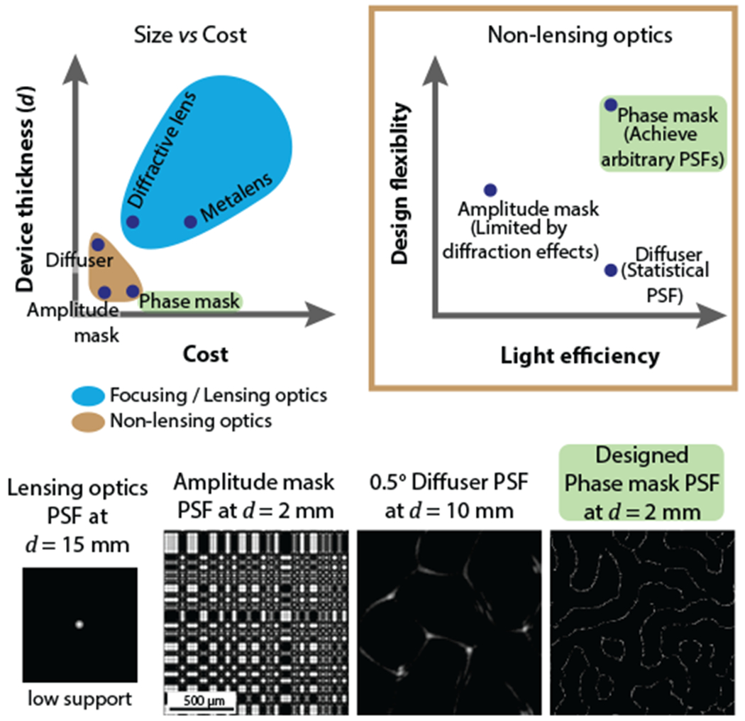
[Top] Non-lensing optics provides a way to achieve thin devices at low-cost. Among the various non-lensing optics, phase-masks are veratile in their designs and can produce a larger space of Point-spread-functions (PSF). [Bottom] PSFs from various optics are shown. Lensing optics have a small PSF support while non-lensing optics display large PSFs. The non-lensing optics’ PSFs were experimentally camptured.
Recently, lenless cameras were demonstrated to achieve small form factors by forgoing the need to capture “image” like measurements on the sensor. Instead, what these cameras capture are highly multiplexed measurements, which are computationally demultiplexed into images by incorporating calibrated camera responses. Inevitably, these cameras have point-spread-functions (PSFs) with large support. The design of the point-spread-functions is instrumental in guaranteeing high-quality reconstructions—however, previous lensless designs lack the precise control of point-spread-functions. One of the core contributions of this paper is a framework to precisely realize high-performance PSFs.
A lensless camera consists of an encoding element or a “mask” placed at a close distance from an imaging sensor. Various masks have been considered like amplitude masks [10], [11], [12], phase gratings [13] and diffuser [14]. Amplitude masks were designed to produce binary PSFs, phase gratings were designed to produce robust nulls, and diffusers were used for its pseudorandom caustic pattern. However, each of these masks is limited in their designability (Fig. 1).
While the design of amplitude masks is straightforward, there are two inherent issues: (1) they block a significant amount of light, and (2) diffraction effects cause the PSF to deviate from the original design. On the other extreme, diffusers are inherently statistically while having a minimal light loss. The statistical nature puts the diffuser low on the design flexibility scale.
For our lensless system, we propose to use phase-masks as our optical masks. Among the various diffraction masks, phase-masks have proven to be versatile in realizing a variety of point-spread-functions [15], [16], [17], [18], [19], [20], with and without the assistance of lenses. Additionally, phase-masks are highly light-efficient and hence operationally better suited for a range of illumination scenarios.
The designability of phase-masks allows us to realize high-performance PSFs and hence improve the overall performance of the lensless system. To that end, we propose a PhlatCam design that benefits from our following contributions:
We propose a Near-field Phase Retrieval (NfPR) framework to design phase-mask that produces the target PSF at the desired device thickness.
We propose a high-performance contour PSF and show it’s superior performance compared to previous lensless PSFs.
We show the application of PhlatCam for (a) 2D imaging at any scene depth, (b) refocusing at medium scene depth, and (c) 3D imaging at close scene depth.
2. Related Work
2.1. Previous Lensless Imagers
Without the lens, a bare sensor captures the average light intensity of the entire scene. [21] has shown imaging with a bare sensor by exploiting shadows cast by defects on the sensor’s cover glass, and the anisotropy of pixel response to achieve some level of light modulation. Due to limited control on the light modulation, the possible reconstruction quality is limited to low resolutions. An alternate way to achieve bare sensor imaging is to have an active illumination behind the object to produce light modulation through shadows [22] or interference fringes [23]. This technique was used to create high-resolution wide field-of-view (FoV) microscopy images. However, adding an active illumination behind the object makes the imaging system bulkier and impractical for photography.
To passively achieve a higher control of light modulation, an encoding “mask” is placed in front of an imaging sensor [7]. Lensless imaging has been shown with a variety of diffractive masks [10], [11], [12], [13], [14], [19], [24]. The masks produce a point-spread-function (PSF) on the sensor which can be undone using computational algorithms to produce high-quality images.
2.2. Diffractive Masks
Diffractive masks used for lensless cameras can be broadly categorized into amplitude masks and phase masks. Amplitude masks were used by [10], [11], [12], [24] and phase masks were used by [13], [14], [19].
2.2.1. Amplitude Masks
An amplitude mask modulates the amplitude of incident light by either passing, blocking, or attenuating photons. For ease of fabrication, a binary amplitude is commonly used, and the light modulation by casting shadows. Hence, the PSF of the amplitude mask is its shadow.
A concerning issue in using an amplitude mask is the light throughput. Since the mask modulates light by creating shadows, a significant amount of photons are lost, leading to low signal-to-noise-ratio (SNR) sensor capture. Low SNR is undesirable for low light scenarios and photon-limited imaging like fluorescence or bioluminescence imaging. Additionally, decoding the lensless sensor capture tends to amplify noise leading to poor reconstruction. Amplitude masks also suffer from diffraction effects, which limit the range of achievable PSFs. Diffraction issue is discussed further in Section 2.3.
2.2.2. Phase Masks
A phase-mask modulates the phase of incident light by the principles of wave optics [25]. Phase-masks allow most of the light to pass through, providing high SNR. Hence, they are desirable for low light scenarios and photon-limited imaging.
We propose to use phase-mask for our lensless camera and present a mask design algorithm to achieve desirable PSFs.
2.3. Mask Design
2.3.1. Amplitude Masks
Among all masks, designing an amplitude mask based on a desirable PSF is the most straightforward. The pattern of a binary amplitude mask is merely the PSF itself, where the bright regions of the PSF correspond to the open areas of the mask, and the dark regions correspond to the blocking areas [7].
However, the range of PSFs achievable using the above mentioned, ray-optics based, amplitude mask design is limited due to diffraction. As a rule of thumb, the Fresnel number NF [26] associated with the amplitude mask can help in determining whether the PSF will be close to the pattern of the mask or different. If the Fresnel number is much greater than 1, then geometrical properties are valid, and the shadow PSF mimics the mask pattern. When the Fresnel number falls below 1, the cast PSF will deviate from the mask pattern. This aspect is elaborated in supplementary Section 2, and the effect of diffraction in amplitude mask PSF is shown in Supp. Fig. 1.
2.3.2. Phase Masks
Odd-symmetry phase gratings were proposed by [27] to achieve robust nulls in the PSF. The wavelength and depth-robust nulls are produced along the axis around which phase gratings have an odd-symmetry. However, this design doesn’t guarantee intensity distributions in the non-null regions of the PSF.
The use of diffuser as a phase mask for lensless imaging was proposed by [14]. Diffusers are low cost and produce caustics patterns. The best performance is achieved from a diffuser when its placed at a distance where it produces the highest contrast caustics. However, since the phase profile of a diffuser is inherently statistical, the optimal distance varies from one to another. Hence, it is harder to design lensless cameras of desired thicknesses with diffusers.
[28] proposed phase mask design using phase retrieval algorithms and subsequently implemented using phase spatial light modulator in [19]. We follow a similar approach in designing our phase mask for a desirable PSF and then fabricate our phase-mask. The camera thickness is a design parameter in our approach and allows us to create lensless cameras of desired thicknesses.
2.4. PSF Engineering
Various PSFs have been used for lensless imaging for their attractive properties. We describe them below.
Separable PSF
A separable PSF is constructed by an outer product of two 1-D vectors. Such construction simplifies the imaging model as convolution along the rows of the image followed by convolution along the columns. In matrix form, this operation can be written as a product of 2-D image with a few small 2-D matrices [10], [11], [24]. An example of separable PSF is shown in Fig. 10, constructed from outer product of two maximum length sequences [10], [29], [30].
Fig. 10.
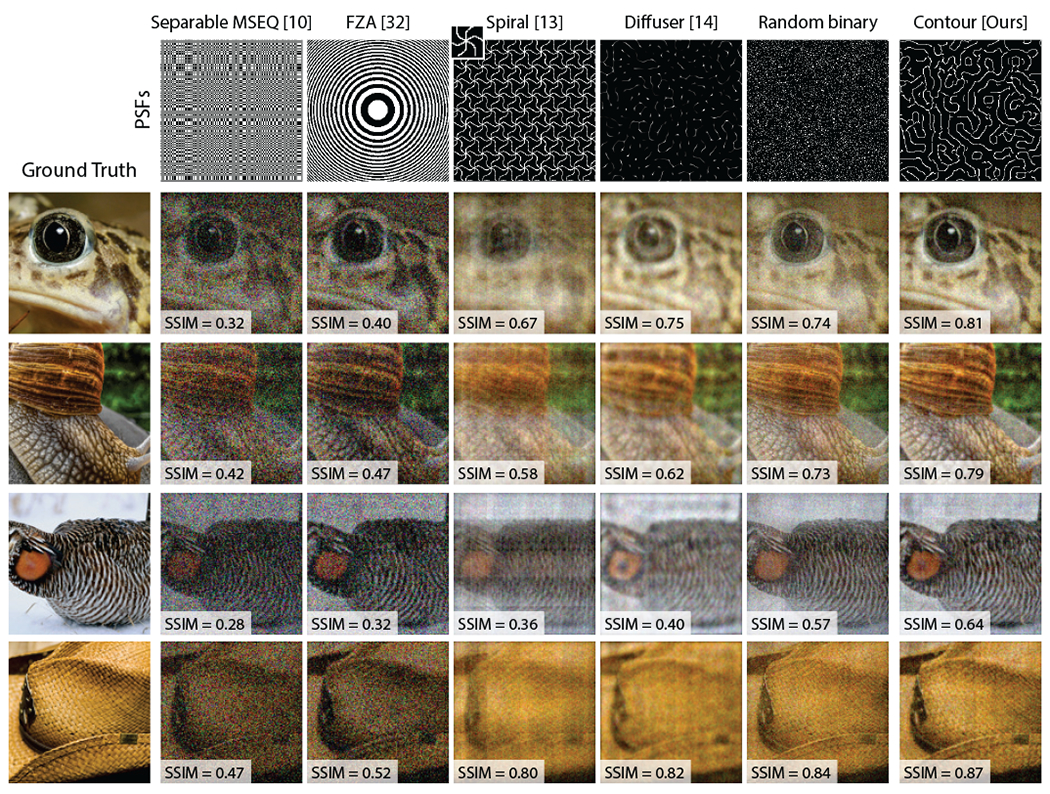
Simulated reconstruction with previously proposed PSFs, random binary PSF and our Contour PSF Random binary PSF satisfies three of the four desired characteristics of PSF However, random binary PSF doesn’t satisfy the fourth characteristic, that is large contiguous regions of zero intensity. As seen from above, contour PSF consistently produces better results.
Fresnel Zone Aperture
A Fresnel Zone Aperture (FZA) PSF is constructed like a Fresnel zone plate [31] and was used by [12], [32]. Multiplying the sensor capture with a virtual FZA results in overlapping moire fringes. Fast reconstruction is done by applying a 2-D Fourier transform on the moiré fringes. An example of FZA PSF is shown in Fig. 10.
Spiral PSF
A spiral PSF was proposed by [27]. To cover a large sensor area, [13] proposed tessellating the spiral PSF. An example of the tessellated spiral PSF is shown in Fig. 10. A single unit of the tessellation is shown on the top left corner.
We propose a high-performance Contour PSF that provides us the ability to perform high-resolution (a) 2D imaging, (b) refocusing, and (c) 3D imaging at different depth ranges.
3. Diffractive Lensless Imaging
3.1. Imaging Architecture
PhlatCam has a fabricated diffractive element called phase mask placed at a distance d from an imaging sensor (Figure 5(a)). A phase mask modulates the phase of incident light and produces a pattern at the sensor through constructive and destructive interference. In the following sections, we’ll describe how the phase mask produces interference pattern and the consequent diffractive imaging model.
Fig. 5.
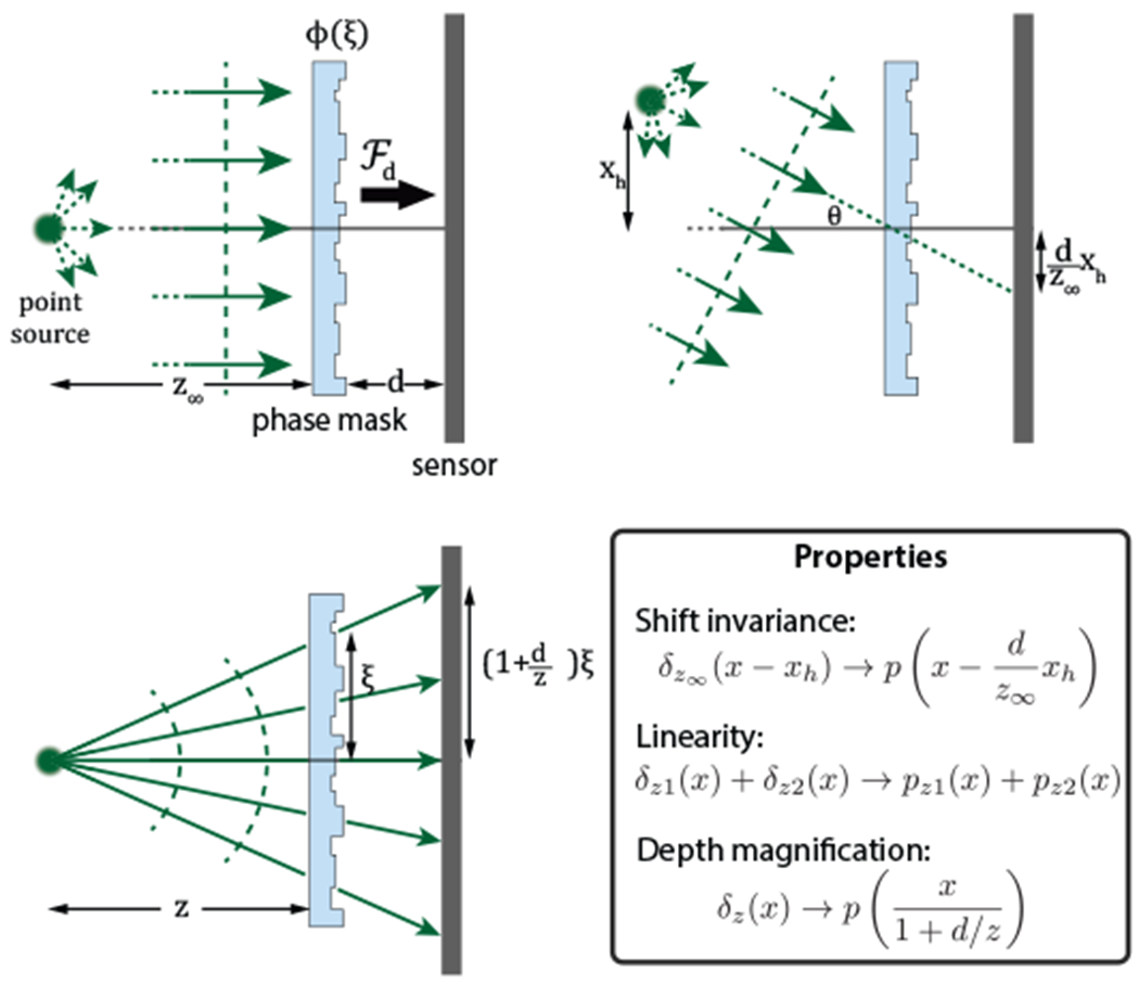
Illustration of properties of phase mask in a lensless imaging setup.
3.2. Propagation
When a phase mask, with phase profile ϕ(ξ, η), is illuminated with a coherent collimated light, the intensity pattern p(x, y) captured by the imaging sensor placed at distance d is given by magnitude square of Fresnel propagation [26]:
| (1) |
where denotes fresnel propagation by distance d and λ is the wavelength of light. For simplicity, let’s consider a one-dimensional (1D) phase mask with phase map ϕ(¾) and drop the scaling term. Then, the pattern produced from collimated light parallel to optical axis is given by
| (2) |
where the quadratic term was expanded and a constant phase term was removed since we are considering only intensity.
3.3. Point Spread Function
The collimated light or planar waves can be said to be generated from an on-axis point source at a sufficiently large distance from the mask. Then, p(x) (or p(x, y) for 2D) can be called as the point-spread-function (PSF) of the system.
If the point source is off-axis, illuminating the phase mask at an angle θ, it imparts a linear phase to Eq. 2 and the resultant intensity pattern is
Hence, an off-axis point source causes a lateral shift of the PSF If the point source is at a distance z∞ and height xh then by paraxial approximation
| (3) |
where δz(x) denotes point source at distance z from the mask. The shift property is illustrated in Figure 5(b) and can be stated as
Property 1. Shift invariance: A lateral shift of point source causes translation of PSF on the sensor plane.
The above property is also called “memory effect” [33], [34] and was recently used to perform non-invasive imaging through scattering media [35], [36], [37] and wavefront sensing [38]. As we will see later, the shift invariance property helps us to write the imaging model as a convolutional model.
For a point source at a finite distance z from the mask, it imparts an additional quadratic phase to Eq. 2 togive an intensity response as:
Here we assumed d ≪ z which would be the case for our lensless cameras. Therefore, following the same notations as Eq. 3 we have
| (4) |
which is a geometrical magnification of the PSF. The magnification property is illustrated in Figure 5(c) and can be stated as
Property 2. An axial shift of point source causes magnification of PSF on the sensor plane.
As we will see later, the PSF variation with scene depth will be exploited for refocusing of images and 3D image reconstruction.
3.4. Convolutional model
A real world 2D scene i (x, y; z) at distance z can be assumed to be made up of incoherent point sources. Each point source will produce a shifted version of PSF pz(x, y) and since the sources are incoherent to each other, the shifted PSFs will add linearly in intensity [26] at the sensor. By Property 1 of the PSF, we can write the imaging model as following convolution model:
| (5) |
Here, b is the sensor’s capture and * denotes 2D convolution over (x, y).
For a 3D scene, the sensor capture is the sum of convolutions at different dephts and the imaging model can be written as:
| (6) |
The above sections established the relation between phase mask and PSF. In the following sections, we propose a high-performance PSF and lay out a method to design phase mask for the desired PSF.
4. Designing PhlatCam
Designing PhlatCam consists of of two parts: (1) PSF engineering and (2) phase-mask optimization. Performance of PhlatCam relies on the PSF while the phas-mask optimization makes the PSF realizable.
4.1. PSF Engineering
A lensless camera encodes an image onto the sensor by convolution of the scene with a PSF. From convolution theorem [39], we can infer that for maximal information transfer, large and almost flat magnitude spectrum is desirable in the PSF. An another way to look at this is that the deconvolution of PSF involves the inversion of the PSF’s frequency spectrum and low values of magnitude spectrum will lead to amplification of noise at those frequencies.
Imaging sensors captures light intensity, which implies that the values in the PSF are always positive. A positive PSF will have larger contribution at DC or the zero-frequency component compared to other frequencies. Hence, efforts need to be taken to minimize the DC component. Additionally, sensors don’t have infinite precision and are usually limited to 8- to 12-bit precision. These two factors also need to be considered when designing the PSF.
Designing the PSF could, potentially, be achieved using many methods such as optimizing over a theoretical metric [8], [40] or using a data-driven approach [17], [41]. In this paper, we take a heuristic approach based on the domain knowledge of signal processing. Considering the previously mentioned factors, we state the desired characteristics of the PSF and the corresponding reasoning as follows:
Contain all directional filters to capture textural frequencies at all angles.
Spatially sparse to minimize the DC component of PSF’s Fourier transform.
High contrast (i.e. binary) to compensate for limited bit depth of sensor pixels.
Large regions of contiguous zero intensity to further compensate for limited bit depth of sensor pixels.
Proposed Contour-based PSF
We make the observation that contour lines with sufficient random orientation satisfies all the criterions mentioned above, as shown in Figure 6. There are, however, many possible ways to generate contour PSFs. In our case, we chose to produce contours from Perlin noise [42] due to it’s guarenteed randomness and the ability to control the sparsity.
Fig. 6.
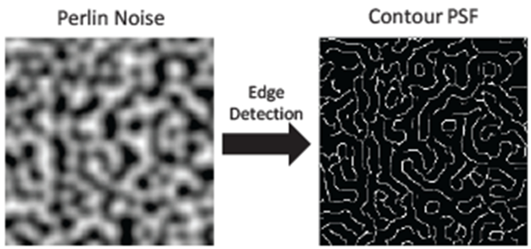
Our Contour PSF is generated by applying canny edge detection on Perlin noise [42].
In graphics, Perlin noise [42] is a popular tool to produce random landscape textures. What we are after is the boundary contours of such landscape textures, which will invariably (a) contain a set of randomly oriented curves that can function as directional filters, (b) be sparse, (c) be binary, and (d) contain large empty regions. To produce the contour PSF, we apply canny edge detection to a generated Perlin noise. Such generation of PSF is a good candidate for lensless imaging and satisfy the above mentioned characteristics. Illustration of generating a contour PSF is shown in Fig. 6. The high performance of our proposed contour-based PSF is validated using the modulation transfer function (MTF) metric in Fig. 7 and using simulated reconstruction in Fig. 10.
Fig. 7. Modulation Transfer Function (MTF) of lensless point-spread-functions (PSFs).
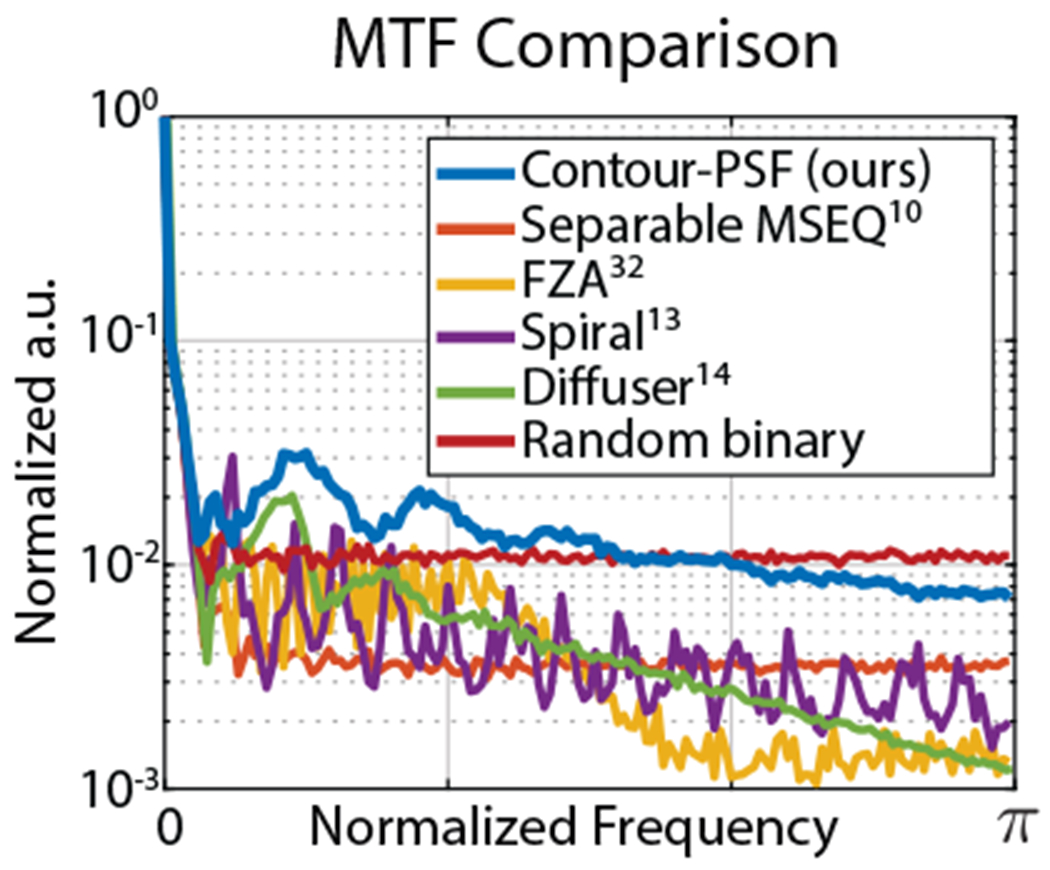
The MTF is computed as the radially averaged magnitude spectrum of the PSFs. The PSFs compared are: Separable MSEQ [10], Fresnel zone apertures (FZA) [32], Tessellated spiral [13], Diffuser [14], Random binary, and our Contour PSF. The PSFs are visualized in Fig. 10. The magnitude spectrum of the proposed Contour PSF remains large for entire frequency range indicating better invertibility characteristic.
4.2. Phase-mask Design
Our goal is to optimize a phase-mask design that produces the target PSF at the target device thickness d (the distance between the sensor and mask). A thing to note is that the phase-mask performs a complex-valued modulation of light wavefront while the target PSF is a real-valued intensity distribution. Hence, obtaining phase-mask profile from the PSF is an undetermined problem. However, there exists computational methods called the phase retrieval algorithms [43] that tries to solve this precise problem of computing complex-valued fields from real-valued intensities.
Usually phase retrieval algorithms are applied in the case of systems involving lens and function under the far-field approximation of Fraunhofer diffraction (implemented with just a Fourier transform) [26], [43]. In our case, we are devoid of lens and are within the regime of near-field Fresnel diffraction (has an additional quadratic phase). . Hence, we call our phase-mask optimization algorithm as Near-field Phase Retrieval (NfPR).
NfPR is motivated by [28] and is similar to the Gerchberg-Saxton (GS) algorithm [44], a popularly used phase retrieval algorithm. The way we differ from the GS algorithm is by replacing the Fourier transforms with near-field Fresnel propagation. NfPR does not guarantee an unique solution. However, what we are after is a phase-mask that can produce the target PSF and not the unique phase-mask profile.
The near-field phase retrieval algorithm for phase mask optimization can be described as follows. The algorithm uses an iterative approach, iterating between the fields at the mask plane and the sensor plane while simultaneously enforcing constraints at the two planes—the amplitude of the field at the mask plane is unity and intensity of the field at the sensor plane is the target engineered PSF. Forward Fresnel propagation is used to go from mask plane to sensor plane, while backward Fresnel propagation (by negating the distance in Eq. 1) is used to go from sensor plane to mask plane. The iterative algorithm is summarized in Alg. 1 and visually illustrated in Fig. 8. The phase mask optimization requires the following inputs: the target PSF, mask to sensor distance, and wavelength of light. The wavelength of light is chosen to be the mid visible wavelength of 532 nm.
Fig. 8.
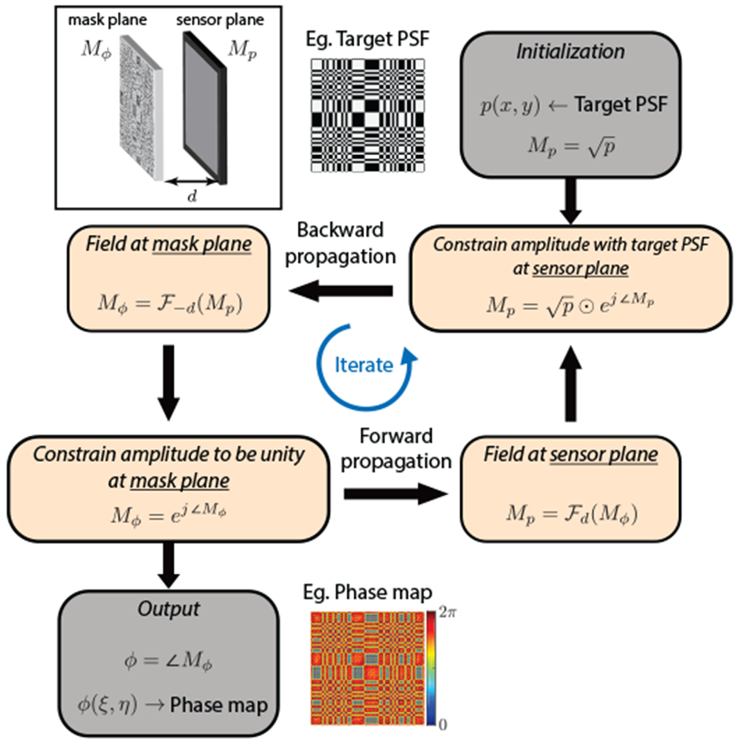
Visual illustration of the phase mask design.
Phase-mask height map
To physically implement the phase-mask, the phase profile needs to be transformed into the height map of the final mask substrate. Assuming n as the refractive index of the mask substrate, the height map is given by:
| (7) |
Fabrication
Advancements in fabrication techniques have made it possible for physically realizing diffractive masks with quick turnaround times. In this paper, we use a recently developed 2-photon lithography 3D printing system [45] that allows for rapid prototyping of different phase-masks without significant overhead preparation. With an optimized final phase-mask design, fabrication can be scaled through the manufacturing pipeline such as photolithography and reactive-ion-etching processes. The fabricated phase-mask is shown in Fig. 2.
Fig. 2.

Phase-masks are essentially transparent material with different heights at different locations. This causes phase modulation of incoming wavefront and resultant wave interference produces the PSF at the sensor plane. The above image shows the closeup image of the phase-mask using in PhlatCam. The right most image was taken using a scanning electron microscope (SEM).
Algorithm 1.
Phase mask design
| Input: Target PSF p(x, y), wavelength λ, mask to sensor distance d and refractive index n of mask substrate. |
| Output: Mask’s phase profile ϕ(ξ, η) and height map h(ξ, η). |
| repeat |
| {Back propagate from sensor to mask} |
| ϕ → phase(Mϕ) |
| Mϕ → ejϕ {Constrain amplitude of mask to be unity} |
| {Forward propagate from mask to sensor} |
| {Constrain amplitude to be } |
| until maximum iterations |
4.3. Reconstruction Algorithms
Recovering the scene image from the sensor measurement can be posed as a convex optimization36 problem, where the forward model is the convolution of PSF with the image. Regularization based on image prior is added to the optimization problem to robustify against measurement noise and avoid large amplification of noise in the reconstruction.
For this section, we will be deviating slightly from the notations in the previous sections. The prominent changes are: ‘x’ will denote the scene (instead of ‘i’) and ‘d’ will denote scene depth (instead of device thickness). In effect, we solve the following minimization problem:
| (8) |
where ∥·∥F denotes the Frobenius norm, denotes the regularization function, and γ is the weighting of the regularization.
4.4. 2D Reconstruction
The reconstruction becomes 2D image reconstruction under two contexts. First, if all the scene elements are sufficiently far (i.e. scene depth ⋙ device thickness), the dependance of PSF with depth is almost none (Eq. 4). In such case, Pd ≈ p∞, and xd ≈ x∞. Second, when refocusing to a particular depth. At both these times, the summation in Eq. 8 is removed and we solve the following problem:
| (9) |
where p = pd(or)p∞, and x = xd (or) x∞ according to the context.
4.4.1. Fast Reconstruction
For fast reconstructions, Tikhonov regularization can be used—which has a closed form solution given by Wiener deconvolution. Using the Convolution Theorem [46], the solution can be computed in real time with the Fast Fourier Transform (FFT) algorithm. By differentiating Eq. 9 and setting to zero, we get the following solution for the Tikhonov regularized reconstruction:
| (10) |
where is the fourier transform operator, (·)* is the complex conjugate operator and ‘⊙’ represents hadamard product.
4.4.2. High-fidelity Reconstruction
The reconstruction quality can be further improved by using total-variation (TV) regularization [47], which uses the image prior that natural images have sparse gradients. The TV regularized minimization problem is given by:
| (11) |
where, Ψ is the 2D gradient operator, and ∥·∥1 is the l1 norm. We opt for an iterative ADMM [48] approach to solve the above problem.
Let H be the 2D convolution matrix and we use the following variable splitting:
Then the ADMM steps at iteration k are as follows:
where,
Sμ is the soft-thresholding operator with a threshold value of μ, and ρw and pz are the Langrage multipliers associated with w and z, respectively. The scalars pw and pz are the penalty parameters that are computed automatically using a tuning strategy. Operations of H and Ψ can be computed using Fast Fourier Transform (FFT), making each step of the ADMM fast.
4.5. 3D Reconstruction
For 3D imaging, we use both TV and sparsity regularizations and solve using ADMM approach. Let H be the 2D convolution matrix with PSF pd at depth d. Then the reconstruction problem is posed as:
We use the following variable splitting:
where Sv = ∑dvd is the sum along depth operator. Then the ADMM stepps at iteration k are as follows:
where,
Sμ is the soft-thresholding operator with a threshold value of μ, and ρw, ρt, and ρz are the Langrage multipliers associated with w, t and z, respectively. The scalars μw, μt, and μz are the penalty parameters that are computed automatically using a tuning strategy. Operations of Hd, Ψ, and S can be computed using Fast Fourier Transform (FFT), making each step of the ADMM fast.
The key difference between the above 3D algorithm and the algorithm presented in [14] is that we use the summing operator S instead of the slicing operator in [14]. The use of summing operator makes each iteration of ADMM much more stable and results in high quality reconstruction within a few iterations.
5. Imaging Prototype
5.1. Prototype preparation
We generated a contour-based PSF with 14% sparsity from Perlin noise [42]. The continuous phase mask profiles (in radians) were optimized at 532 nm wavelength of light with 2 pm spatial resolution to produce the PSF at sensor to mask distance of 1.95 mm. The height map of the phase-mask was computed for the mask substrate with refractive index of 1.52. The height map was further discretized into height steps of 200 nm to fit the specifications of fabrication. The phase mask was fabricated using two-photon lithography 3D printer (Photonic Professional GT, Nanoscribe GmbH [45]). The phase mask was printed on a 700 μm thick, 25 mm square fused silica glass substrate using Nanoscribe’s IP-DIP photoresist in a Dip-in Liquid Lithography (DiLL) mode with a 63× microscope objective lens. The IP-DIP has a refractive index of 1.52. The fabricated phase mask is shown in Fig. 2.
We used a FLIR Blackfly S color camera with Sony IMX183 sensor to build our prototype. Without binning, the pixel pitch per color channel is 4.8 μm, and with binning, the pixel pitch per color channel is 9.6 μm. The camera housing was replaced with a 3D printed housing to get unobstructed access to the protective glass on the sensor. The phase mask was affixed (face down) on the protective glass of the sensor using double-sided adhesive carbon tape. Two layers of carbon tape were sufficient to attain the desired distance (1.95 mm) between the phase mask and the sensor, the distance at which the PSFs appear the sharpest. The affixing carbon tape also acted as a square aperture (6.7 mmx 5.3 mm) to restrict the shifts of the PSF to be within the sensor.
The PSF design, optimized phase mask profile and comparison of PSF from 3D printed phase mask is shown in Fig. 9.
Fig. 9.

The proposed PSF, designed phase-mask, and the experimentally realized PSF of PhlatCam are shown. The experimental PSF closely resembles the proposed PSF design, showing the effectiveness of the phase mask design framework.
Calibration
There can be discrepancies between the physically implemented PSFs and the target engineered PSFs due to phase mask height discretization and fabrication inaccuracies. Hence, we experimentally capture the PSFs and use these PSFs for our computation. We approximate a point source by back illuminating a pinhole aperture and capturing sensor data by placing prototypes at different desired depths. For the plot Figure 11, PSFs were captured at distances ranging from 7 in (~178 mm) to 13 in (~330 mm), with steps of 1 in (25.4 mm) using a pinhole aperture of 1 mm diameter. For photography example (Figs. 12,17), PSF was captured at 16 in (~406 mm). The PSF for microscopy example (Fig. 13) was captured at 10 mm from the fluorescence filter using a pinhole aperture of 15 μm diameter. For refocusing (Fig. 15) and 3D imaging (Fig. 16), PSFs were captured at distances ranging from 10 mm to 110 mm, with steps: 1 mm for range 10–30 mm, and 5 mm for range 30–110 mm, using a pinhole aperture of 250 μm diameter.
Fig. 11.

Experimental evaluation of our camera’s resolution using fluorescent USAF target. The inserts are shown for line pairs with contrast close to 20% or higher.
Fig. 12. Experimental results: Photography.
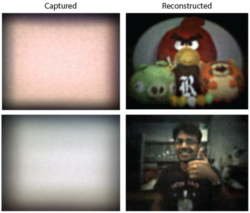
The shortest distance to the scene is about 0.5 m, extending all the way to 3 m in the bottom scene. The bottom scene is a frame from video reconstruction. The video can be found in the supplementary material.
Fig. 17. Experimental comparisons.
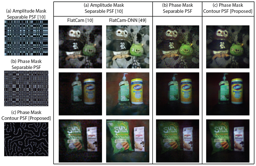
We experimentally compare results from three different prototypes — (a) amplitude mask designed for separable PSF (FlatCam [10]), (b) phase mask designed for separable PSF, and (c) proposed phase mask designed for Contour PSF. The camera thicknesses are approximately 2 mm. FlatCam reconstructions are performed using Tikhonov regularization [10], and using deep learning method [49]. Both the phase-mask reconstructions are performed with Eq. 9. The proposed PhlatCam produces cleaner and higher quality images.
Fig. 13. Experimental results: Microscopy.
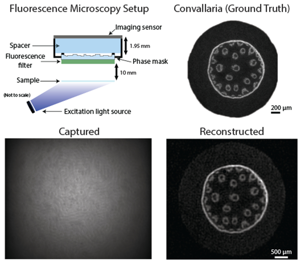
[Top-left] Fluorescence microscopy setup. [Top-right] Ground truth image of fluorescent sample taken using 2.5× microscope objective lens. The sample is a root cell from lily-of-the-valley (Convallaria majalis) stained with green fluorescent dye. [Bottom] Sample capture (at 10 mm away) and reconstruction.
Fig. 15.
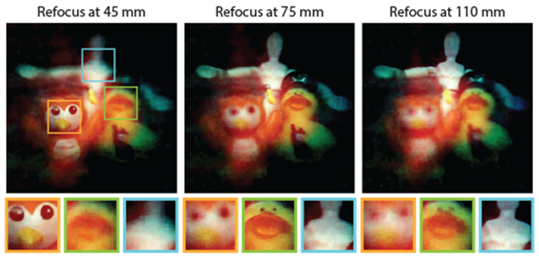
We showcase the refocusing ability of PhlatCam. Three objects at three different distances comes into focus when we use the appropriate depth PSF for the reconstruction.
Fig. 16.
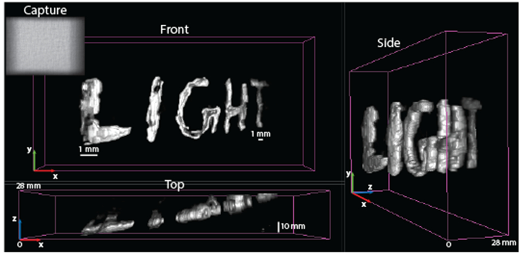
We showcase the 3D image reconstruction ability of PhlatCam at very close distance. The scene is a handwritten text, written using phosphorescent paint. The letter ‘L’ is at the closest distance from the camera, at 10 mm, and the letter ‘T’ is at 38 mm from the camera. Hence, the scene ranges from 0 to 28 mm.
5.2. Resolution characterization
From the lensless camera geometry, theoretical upper-limit resolution of a lensless camera can be derived as:
| (12) |
From experimental testing using fluorescent USAF target, we find that using contour PSF achieves close to theoretical resolution as shown in Fig. 11. The pixel pitch of the camera is 4.8 μm.
5.3. Depth-dependance Characterization
PhlatCam has depth-dependent PSF that can be exploited for refocusing scenes at different depths and also to perform 3D imaging. The effect of depth on PSF is magnification or scaling, where the PSF shrinks at the rate of 1/depth as the scene depth increases (Eq. 4). This effect is a direct outcome of Fresnel propagation. The correlation of PSFs rapidly decreases at closer depths and has broader correlation profiles at farther depths. This property can be used for 2D imaging at far depths, computational depth refocusing of scenes at medium depth range, and 3D imaging of scenes at a closer depth range. Fig. 14 shows the magnification and correlation of the depth-dependant PSFs.
Fig. 14.
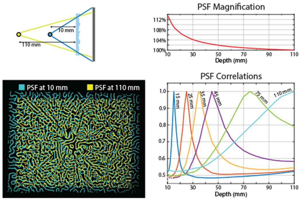
PhlatCam has depth dependent PSF that magnifies as the scene gets closer. The magnification falls with inverse depth relation. By looking at the correlation of PSFs, we can broadly categorize scene depth into 3 regimes. At close distances, the correlation falls quickly, enabling us to reconstruct 3D images. At the medium distances, the correlation falls gradually over a wider depth range. In this distance range, we can perform computational refocusing. At much larger depth, the dependence of PSF with depth saturates and all far scene points can be said to be beyond the hyperfocal distance of PhlatCam, thereby allowing only reconstruction of 2D images.
5.4. Imaging Experiments
5.4.1. 2D Imaging
We show 2D imaging using PhlatCam under various scenarios. Photography experiments are shown in Figs. 12, 17, while microscopy experiment is shown in Fig. 13. For all the reconstructions, the camera was 2 × 2 binned to have a pixel pitch of 9.6 pm. Additionally, the biography images are also taken with the PhlatCam.
We, also, experimentally (Fig. 17) compare the proposed PhlatCam with two other prototypes: (a) amplitude mask designed for separable PSF (FlatCam [10]), (b) phase mask designed for separable PSF, and (c) proposed phase mask designed for Contour PSF. FlatCam reconstructions are performed using Tikhonov regularization [10], and using deep learning method [49]. Both the phas-mask reconstructions are performed with Eq. 9.
5.4.2. Image Refocusing
At medium depth ranges, the depth-dependant PSFs uncorrelate slowly. Hence, the exact 3D reconstruction would e ill-conditioned. However, the PSF correlation fall-off can be exploited for performing computational refocusing from single captured measurements. We perform refocusing by reconstructing the image from the single capture by choosing the appropriate depth PSF. Scene points away from the selected depth appear blurry while the scene points at the selected depth plane appear sharp. Our refocusing experiment is shown in Fig. 15.
5.4.3. 3D Imaging
At very close depth range, the depth-dependant PSFs uncorrelate at a fast rate. This property can be exploited to perform 3D imaging. Our 3D imaging experiment is shown in Fig. 16.
6. Discussion and Conclusion
We demonstrated PhlatCam, a designed lensless imaging system that can perform high-fidelity 2D imaging, computational refocusing, and 3D imaging. These abilities are made possible by our proposed Contour PSF and the phase mask design algorithm. We used traditional optimization-based algorithms to reconstruct images in this paper. In the future, we will incorporate data-driven methods (like [49], [50]), to improve the reconstruction quality.
In this work, we used a heuristic approach borne from concepts of signal processing to engineer a high-performance PSF. As a future direction, we aim to optimize the PSF over a theoretical metric or through an end-to-end data-driven approach.
Supplementary Material
Fig. 3.

Our proposed phase-mask framework takes the input of target PSF and the desired device geometry and outputs an optimized phase-mask design.
Fig. 4. Conventional imaging and PhlatCam.
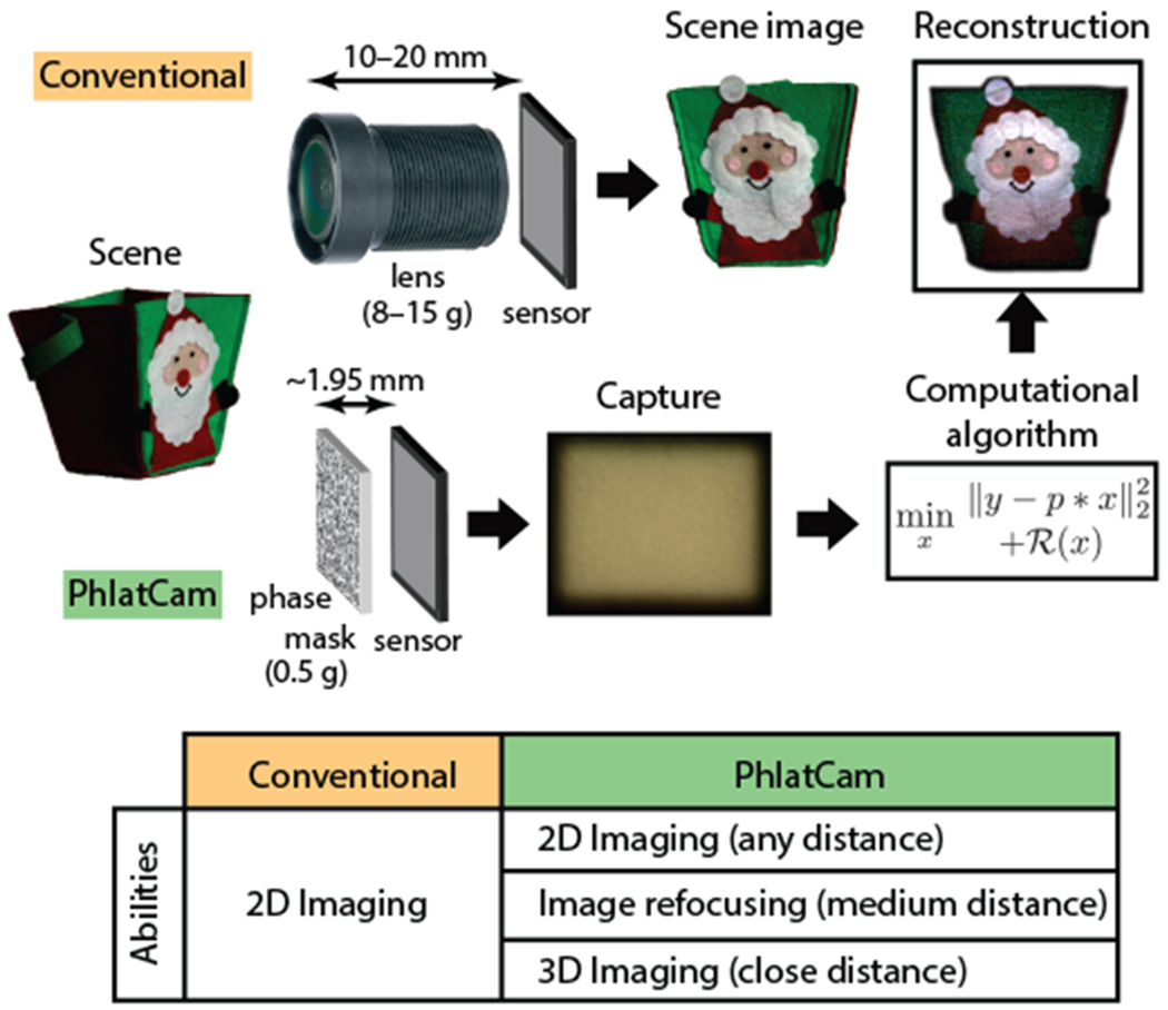
PhlatCam is 5–10× thinner and can reconstruct high-fidelity images from multiplexed measurements. Additionally, PhlatCam can function in more ways than conventional camera. Specifically PhlatCam can produce 2D images for any scene distance, refocused images at medium distance and 3D imaging at close distance.
Acknowledgments
The authors would like to thank Salman S. Khan, IIT Madras, and Jasper Tan, Rice University, for assisting in FlatCam reconstructions [10], [49]. The authors would also like to thank Fan Ye, Rice university, for assisting in the initial steps of fabrication. This work was supported in part by NSF CAREER: IIS-1652633, DARPA NESD: HR0011-17-C0026 and NIH Grant: R21EY029459.
Biographies

Vivek Boominathan received the B.Tech degree in Electrical Engineering from the Indian Institute of Technology Hyderabad, Hyderabad, India, in 2012, and the M.S. and Ph.D. degree in 2016 and 2019, from the Department of Electrical and Computer Engineering, Rice University, Houston, TX, USA. He is currently a Postdoctoral Associate with Rice University, Houston, TX. His research interests lie in the areas of computer vision, signal processing, wave optics, and computational imaging.

Jesse K. Adams received the B.Sc. degree in physics from the University of North Florida, Jacksonville, FL, USA, in 2014 and the M.Sc. and Ph.D. degrees in applied physics from Rice University, Houston, TX, USA in 2017 and 2019, respectively. After his Ph.D., he received a Cyclotron Road Fellowship hosted at Lawrence Berkeley National Laboratory designed to provide training, mentorship and networking tailored for transitioning innovative concepts into transformative products. His research interests lie in the areas of nanofabrication, optics, neuroengineering, and computational imaging.

Jacob T. Robinson received the B.S. degree in physics from the University of California, Los Angeles, Los Angeles, CA, USA and the Ph.D. degree in applied physics from Cornell University, Ithaca, NY, USA. After his Ph.D., he worked as a Postdoctoral Fellow with the Chemistry Department, Harvard University. He is currently an Associate Professor with the Department of Electrical & Computer Engineering and Bioengineering, Rice University, Houston, TX, USA, and an Adjunct Assistant Professor in neuroscience, Baylor College of Medicine, Houston, TX, USA. He joined Rice University in 2012, where he currently works on nanotechnologies to manipulate and measure brain activity in humans, rodents, and small invertebrates. Dr. Robinson is currently a Co-Chair of the IEEE Brain Initiative, and the recipient of a Hammill Innovation Award, NSF NeuroNex Innovation Award, Materials Today Rising Star Award, and a DARPA Young Faculty Award.

Ashok Veeraraghavan received the bachelor’s degree in electrical engineering from the Indian Institute of Technology, Madras, Chennai, India, in 2002 and the M.S. and Ph.D. degrees from the Department of Electrical and Computer Engineering, University of Maryland, College Park, MD, USA, in 2004 and 2008, respectively. He is currently an Associate Professor of Electrical and Computer Engineering, Rice University, Houston, TX, USA. Before joining Rice University, he spent three years as a Research Scientist at Mitsubishi Electric Research Labs, Cambridge, MA, USA. His research interests are broadly in the areas of computational imaging, computer vision, machine learning, and robotics. Dr. Veeraraghavan’s thesis received the Doctoral Dissertation Award from the Department of Electrical and Computer Engineering at the University of Maryland. He is the recipient of the National Science Foundation CAREER Award in 2017. At Rice University, he directs the Computational Imaging and Vision Lab.
Contributor Information
Vivek Boominathan, Department of Electrical and Computer Engineering, Rice University, Houston, TX, 77005.
Jesse K. Adams, Applied Physics Program, Rice University, Houston, TX, 77005
Jacob T. Robinson, Department of Electrical and Computer Engineering, Rice University, Houston, TX, 77005
Ashok Veeraraghavan, Department of Electrical and Computer Engineering, Rice University, Houston, TX, 77005.
References
- [1].Geiger A, Lenz P, Stiller C, and Urtasun R, “Vision meets robotics: The kitti dataset,” The International Journal of Robotics Research, vol. 32, no. 11, pp. 1231–1237, 2013. [Google Scholar]
- [2].Cornacchia M, Ozcan K, Zheng Y, and Velipasalar S, “A survey on activity detection and classification using wearable sensors,” IEEE Sensors Journal, vol. 17, no. 2, pp. 386–403, 2016. [Google Scholar]
- [3].Eliakim R, Fireman Z, Gralnek I, Yassin K, Waterman M, Kopelman Y, Lachter J, Koslowsky B, and Adler S, “Evaluation of the pillcam colon capsule in the detection of colonic pathology: results of the first multicenter, prospective, comparative study,” Endoscopy, vol. 38, no. 10, pp. 963–970, 2006. [DOI] [PubMed] [Google Scholar]
- [4].Wei S-E, Saragih J, Simon T, Harley AW, Lombardi S, Perdoch M, Hypes A, Wang D, Badino H, and Sheikh Y, “Vr facial animation via multiview image translation,” ACM Transactions on Graphics (TOG), vol. 38, no. 4, p. 67, 2019. [Google Scholar]
- [5].Ren Z, Meng J, and Yuan J, “Depth camera based hand gesture recognition and its applications in human-computer-interaction,” in 2011 8th International Conference on Information, Communications & Signal Processing IEEE, 2011, pp. 1–5. [Google Scholar]
- [6].Tan J, Niu L, Adams JK, Boominathan V, Robinson JT, Baraniuk RG, and Veeraraghavan A, “Face detection and verification using lensless cameras,” IEEE Transactions on Computational Imaging, vol. 5, no. 2, pp. 180–194, 2018. [Google Scholar]
- [7].Boominathan V, Adams JK, Asif MS, Avants BW, Robinson JT, Baraniuk RG, Sankaranarayanan AC, and Veeraraghavan A, “Lensless Imaging: A computational renaissance,” IEEE Signal Processing Magazine, vol. 33, no. 5, pp. 23–35, September 2016. [Google Scholar]
- [8].Peng Y, Fu Q, Heide F, and Heidrich W, “The diffractive achromat full spectrum computational imaging with diffractive optics,” ACM Trans. Graph, vol. 35, no. 4, pp. 31:1–31:11, 2016. [DOI] [PMC free article] [PubMed] [Google Scholar]
- [9].Khorasaninejad M, Chen WT, Devlin RC, Oh J, Zhu AY, and Capasso F, “Metalenses at visible wavelengths: Diffraction-limited focusing and subwavelength resolution imaging,” Science, vol. 352, no. 6290, pp. 1190–1194, 2016. [DOI] [PubMed] [Google Scholar]
- [10].Asif MS, Ayremlou A, Sankaranarayanan A, Veeraraghavan A, and Baraniuk RG, “FlatCam: Thin, Lensless Cameras Using Coded Aperture and Computation,” IEEE Transactions on Computational Imaging, vol. 3, no. 3, pp. 384–397, September 2017. [Google Scholar]
- [11].Adams JK, Boominathan V, Avants BW, Vercosa DG, Ye F, Baraniuk RG, Robinson JT, and Veeraraghavan A, “Singleframe 3D fluorescence microscopy with ultra-miniature lensless FlatScope,” Science Advances, vol. 3, no. 12, p. e1701548, December 2017. [DOI] [PMC free article] [PubMed] [Google Scholar]
- [12].Shimano T, Nakamura Y, Tajima K, Sao M, and Hoshizawa T, “Lensless light-field imaging with fresnel zone aperture: quasi-coherent coding,” Applied optics, vol. 57, no. 11, pp. 2841–2850, 2018. [DOI] [PubMed] [Google Scholar]
- [13].Stork DG and Gill PR, “Optical, mathematical, and computational foundations of lensless ultra-miniature diffractive imagers and sensors,” International Journal on Advances in Systems and Measurements, vol. 7, no. 3, p. 4, 2014. [Google Scholar]
- [14].Antipa N, Kuo G, Heckel R, Mildenhall B, Bostan E, Ng R, and Waller L, “Diffusercam: lensless single-exposure 3d imaging,” Optica, vol. 5, no. 1, pp. 1–9, 2018. [Google Scholar]
- [15].Pavani SRP, Thompson MA, Biteen JS, Lord SJ, Liu N, Twieg RJ, Piestun R, and Moerner W, “Three-dimensional, singlemolecule fluorescence imaging beyond the diffraction limit by using a double-helix point spread function,” Proceedings of the National Academy of Sciences, vol. 106, no. 9, pp. 2995–2999,2009. [DOI] [PMC free article] [PubMed] [Google Scholar]
- [16].Chen J, Hirsch M, Heintzmann R, Eberhardt B, and Lensch H, “A phase-coded aperture camera with programmable optics,” Electronic Imaging, vol. 2017, no. 17, pp. 70–75, 2017. [Google Scholar]
- [17].Wu Y, Boominathan V, Chen H, Sankaranarayanan A, and Veeraraghavan A, “Phasecam3d—learning phase masks for passive single view depth estimation,” in 2019 IEEE International Conference on Computational Photography (ICCP) IEEE, 2019, pp.1–12 [Google Scholar]
- [18].Chang J, Sitzmann V, Dun X, Heidrich W, and Wetzstein G, “Hybrid optical-electronic convolutional neural networks with optimized diffractive optics for image classification,” Scientific reports, vol. 8, no. 1, p. 12324, 2018. [DOI] [PMC free article] [PubMed] [Google Scholar]
- [19].Chi W and George N, “Optical imaging with phase-coded aperture,” Optics Express, vol. 19, no. 5, p. 4294, 2011. [DOI] [PubMed] [Google Scholar]
- [20].Wang W, Ye F, Shen H, Moringo NA, Dutta C, Robinson JT, and Landes CF, “Generalized method to design phase masks for 3d super-resolution microscopy,” Optics express, vol. 27, no. 3, pp. 3799–3816, 2019. [DOI] [PubMed] [Google Scholar]
- [21].Kim G, Isaacson K, Palmer R, and Menon R, “Lensless photography with only an image sensor,” Applied Optics, vol. 56, no. 23, p. 6450, August 2017. [DOI] [PubMed] [Google Scholar]
- [22].Ozcan A and Demirci U, “Ultra wide-field lens-free monitoring of cells on-chip,” Lab Chip, vol. 8, no. 1, pp. 98–106, December 2008. [DOI] [PubMed] [Google Scholar]
- [23].Seo S, Su T-W, Tseng DK, Erlinger A, and Ozcan A, “Lensfree holographic imaging for on-chip cytometry and diagnostics,” Lab Chip, vol. 9, no. 6, pp. 777–787, March 2009. [DOI] [PMC free article] [PubMed] [Google Scholar]
- [24].DeWeert MJ and Farm BP, “Lensless coded-aperture imaging with separable Doubly-Toeplitz masks,” Optical Engineering, vol. 54, no. 2, p. 023102, 2015. [Google Scholar]
- [25].Born M and Wolf E, Principles of optics: electromagnetic theory of propagation, interference and diffraction of light. Elsevier, 2013 [Google Scholar]
- [26].Goodman JW, Introduction to Fourier Optics, Third Edition Roberts & Co, 2004. [Google Scholar]
- [27].Stork DG and Gill PR, “Lensless Ultra-Miniature CMOS Computational Imagers and Sensors,” SENSORCOMM 2013: The Seventh International Conference on Sensor Technologies and Applications, pp. 186–190, 2013. [Google Scholar]
- [28].Chi W and George N, “Phase-coded aperture for optical imaging,” Optics Communications, vol. 282, no. 11, pp. 2110–2117, 2009. [Google Scholar]
- [29].Golomb SW et al. , Shift register sequences. Aegean Park Press, 1967. [Google Scholar]
- [30].MacWilliams FJ and Sloane NJ, “Pseudo-random sequences and arrays,” Proceedings of the IEEE, vol. 64, no. 12, pp. 17151729, 1976. [Google Scholar]
- [31].Fresnel A-J, “Calcul de i’intensité de la lumière au centre de l’ombre d’un écran et d’une ouverture circulaires éclairés par un point radieux,” in Mémoires de l’Académie des sciences de l’lnstitut de France. Imprimerie royale (Paris), 1821, ch. Note I, pp. 456–464. [Google Scholar]
- [32].Tajima K, Shimano T, Nakamura Y, Sao M, and Hoshizawa T, “Lensless light-field imaging with multi-phased fresnel zone aperture,” in 2017 IEEE International Conference on Computational Photography (ICCP) IEEE, May 2017, pp. 1–7. [Google Scholar]
- [33].Freund I, Rosenbluh M, and Feng S, “Memory effects in propagation of optical waves through disordered media,” Physical Review Letters, vol. 61, no. 20, pp. 2328–2331, 1988. [DOI] [PubMed] [Google Scholar]
- [34].Feng S, Kane C, Lee PA, and Stone AD, “Correlations and fluctuations of coherent wave transmission through disordered media,” Physical Review Letters, vol. 61, no. 7, pp. 834–837, August 1988. [DOI] [PubMed] [Google Scholar]
- [35].Bertolotti J, van Putten EG, Blum C, Lagendijk A, Vos WL, and Mosk AP, “Non-invasive imaging through opaque scattering layers,” Nature, vol. 491, no. 7423, pp. 232–234, November 2012. [DOI] [PubMed] [Google Scholar]
- [36].Katz O, Small E, and Silberberg Y, “Looking around corners and through thin turbid layers in real time with scattered incoherent light,” Nature Photonics, vol. 6, no. 8, pp. 549–553, July 2012. [Google Scholar]
- [37].Yang X, Pu Y, and Psaltis D, “Imaging blood cells through scattering biological tissue using speckle scanning microscopy,” Optics Express, vol. 22, no. 3, p. 3405, February 2014. [DOI] [PubMed] [Google Scholar]
- [38].Berto P, Rigneault H, and Guillon M, “Wavefront-sensing with a thin diffuser,” Optics Letters, vol. 42, no. 24, p. 5117, December 2017. [DOI] [PubMed] [Google Scholar]
- [39].Oppenheim Alan V, Willsky Alan S, Hamid S, and Hamid Nawab S, “Signals and systems,” ISBN-10, Pearson press, USA, 1996. [Google Scholar]
- [40].Shechtman Y, Sahl SJ, Backer AS, and Moerner W, “Optimal point spread function design for 3d imaging,” Physical review letters, vol. 113, no. 13, p. 133902, 2014. [DOI] [PMC free article] [PubMed] [Google Scholar]
- [41].Sitzmann V, Diamond S, Peng Y, Dun X, Boyd S, Heidrich W, Heide F, and Wetzstein G, “End-to-end optimization of optics and image processing for achromatic extended depth of field and super-resolution imaging,” ACM Transactions on Graphics (TOG), vol. 37, no. 4, pp. 1–13, 2018. [Google Scholar]
- [42].Perlin K, “Improving noise,” in ACM Transactions on Graphics (TOG), vol. 21, no. 3 ACM, 2002, pp. 681–682. [Google Scholar]
- [43].Fienup JR, “Phase retrieval algorithms: a comparison,” Applied Optics, vol. 21, no. 15, p. 2758, August 1982. [DOI] [PubMed] [Google Scholar]
- [44].Gerchberg RW and Saxton WO, “A practical algorithm for the determination of phase from image and diffraction plane pictures,” Optik, vol. 35, no. 2, pp. 237–246, 1972. [Google Scholar]
- [45].“Nanoscribe gmbh,” https://www.nanoscribe.de/. [Google Scholar]
- [46].Oppenheim AV, Discrete-time signal processing. Pearson Education India, 1999. [Google Scholar]
- [47].Rudin LI, Osher S, and Fatemi E, “Nonlinear total variation based noise removal algorithms,” Physica D: nonlinear phenomena, vol. 60, no. 1–4, pp. 259–268, 1992. [Google Scholar]
- [48].Boyd S, Parikh N, Chu E, Peleato B, Eckstein J et al. , “Distributed optimization and statistical learning via the alternating direction method of multipliers,” Foundations and Trends® in Machine learning, vol. 3, no. 1, pp. 1–122, 2011. [Google Scholar]
- [49].Khan SS, Adarsh V, Boominathan V, Tan J, Veeraraghavan A, and Mitra K, “Towards photorealistic reconstruction of highly multiplexed lensless images,” in Proceedings of the IEEE International Conference on Computer Vision, 2019, pp. 7860–7869. [Google Scholar]
- [50].Monakhova K, Yurtsever J, Kuo G, Antipa N, Yanny K, and Waller L, “Learned reconstructions for practical mask-based lensless imaging,” Optics express, vol. 27, no. 20, pp. 28075–28090, 2019. [DOI] [PubMed] [Google Scholar]
Associated Data
This section collects any data citations, data availability statements, or supplementary materials included in this article.


