Abstract
Penetrating microelectrode arrays with 2000 μm2 sputtered iridium oxide (SIROF) electrode sites were implanted in cat cerebral cortex, and their long-term electrochemical performance evaluated in vivo by cyclic voltammetry (CV), electrochemical impedance spectroscopy (EIS), and current pulsing. Measurements were made from days 33 to 328 postimplantation. The CV-defined charge storage capacity, measured at 50 mV/s, increased linearly with time over the course of implantation for two arrays and was unchanged for one array. A modest decrease in 1 kHz impedance was also observed. These results suggest an ongoing increase in the apparent electrochemical surface area of the electrodes, which is attributed to electrical leakage pathways arising from cracking of Parylene insulation observed by SEM of explanted arrays. During current pulsing with a 0.0 V interpulse bias, the electrodes readily delivered 8 nC/phase in vitro, but some channels approached or exceeded the water reduction potential during in vivo pulsing. The charge injection capacity in vivo increased linearly with the interpulse bias (0–0.6 V Ag∣AgCl) from 11.5 to 21.8 nC/ph and with pulse width (150–500 μs) from 8.8 to 14 nC/ph (at 0.0 V bias). These values are lower than those determined from measurements in buffered physiological saline, emphasizing the importance of in vivo measurements in assessing chronic electrode performance. The consequence of current leakage pathways on the charge-injection measurements is also discussed.
Index Terms: Charge injection, impedance, microelectrode, neural recording, neural stimulation
I. Introduction
MICROELECTRODES chronically implanted in the central nervous system are being developed for neural recording and stimulation in sensory and motor prostheses. For brain-machine applications, recording electrodes capable of resolving signal-unit neural activity will be implanted in the cortex to provide signals for prostheses that allow patients to volitionally control external devices. Typically, the recording electrodes will have a geometric surface area (GSA) of < 1000 μm2 and, to facilitate signal processing, must record neuronal action potentials with a signal-to-noise ratio (SNR) of greater than about 5:1 [1]. Cortical microelectrodes are also used for neural stimulation to modulate disease symptoms or restore lost sensory function, such as hearing and vision. Studies by McCreery et al. [2], [3] in cat cortex and Schmidt et al. [4] in human cortex suggest that functional charge thresholds for microelectrode stimulation are on the order of 1–3 nC/phase. To achieve focused stimulation of a small cortical volume, an electrode GSA of ~2000 μm2 has been employed, resulting in threshold charge densities of 50–100 μC/cm2 [5].
A critical factor in the success of these prostheses is maintaining stable long-term communication between the electrodes and nearby neurons. This is particularly important for single-unit recording, where microelectrodes cannot record from neurons greater than about 100 μm away [6]. Loss of communication may occur by several mechanisms, including peri-electrode gliosis [1], [7] and neuronal death or inactivity [8], [9]. Both are likely related to the local inflammatory response. Tissue encapsulation also reduces the charge injection capacity of stimulation electrodes by limiting the transport of counterions to the electrode [10].
Given the importance of the chronic stability of the electrode–tissue interface for both recording and stimulation, the goal of this study was to characterize the evolution of the in vivo electrochemical properties of the microelectrodes over the course of a long-term implantation (>300 days) in cat cerebral cortex. The microelectrodes were based on the Utah Array [11], [12] and were coated with sputtered iridium oxide (SIROF) as a low-impedance, high-charge injection capacity coating [13]. Cyclic voltammetry (CV), impedance spectroscopy, and voltage transients during current pulsing were used to characterize the electrodes in vivo as well as in buffered physiological saline prior to implantation.
II. Methods
A. Microelectrode Arrays
Penetrating microelectrode arrays were fabricated by Black- rock Microsystems using methods that have been described in detail [14], [15]. As shown in Fig. 1, each array has 16 1.0-mm-long electrode shafts in a 4 × 4 arrangement with a tip-to-tip separation of 400 μm. The electrode tips were coated at EIC Laboratories with 300-nm-thick SIROF as a low-impedance coating. The details of the SIROF deposition process have been reported previously [13]. The SIROF was deposited on the electrode tips and at least 100 μm down each shaft using an aluminum foil mask to occlude the remainder of the array. The array was then encapsulated with Parylene-C at Blackrock Microsystems. SIROF electrode sites with a nominal GSA of 2000 μm2 were created by plasma etching the Parylene-C using an aluminum foil mask that extended about 50 μm down the electrode shafts. Previous studies have shown that the exposed area of these electrodes is variable due to the difficulty in achieving uniform masking across the array, although the SIROF electrodes exhibited suitably low impedance and high charge injection capacities for neural applications [16]. Each implant was comprised of two 16-channel arrays attached to a single head-mounted percutaneous CerePort connector (Blackrock) as shown in Fig. 2. Prior to implantation, the implants were sterilized by autoclaving or ethylene oxide.
Fig. 1.
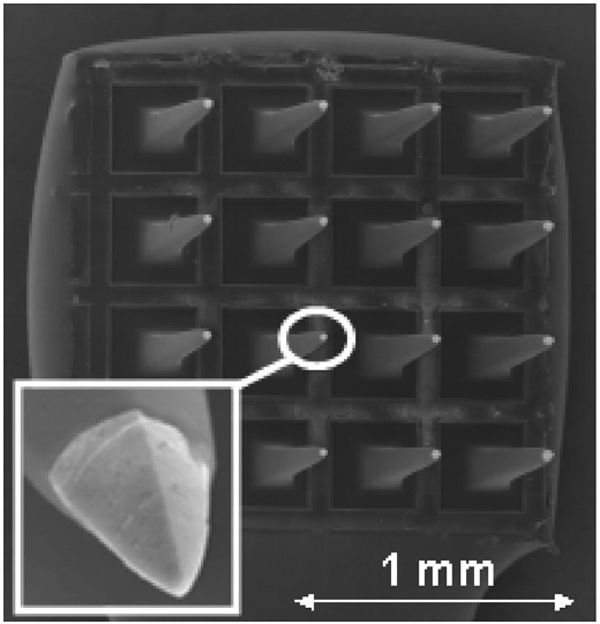
Scanning electron micrograph of a 16-electrode array. The SIROF coating appears as the light-colored tip at the end of each pyramidal electrode shaft. The geometry of the electrode tip is shown in more detail in the inset.
Fig. 2.
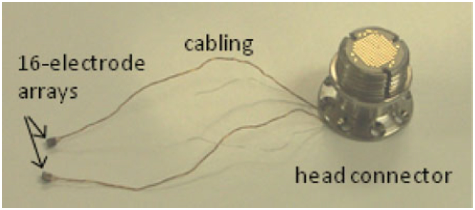
Dual-array implant with a head-mounted connector. The arrays were implanted into the left and right postcruciate gyrus of the sensorimotor cerebral cortex.
B. Implantation
Male domestic cats, age 11–18 months, were employed in the study. The animal protocol was approved by the Institutional Animal Care and Use Committee at Huntington Medical Research Institutes. The implant assembly was fixed to each animal’s skull and one array placed in the cerebral cortex on each side of the brain. In preparation for the implantation, the cats received ketamine-acepromazine preanesthesia, and then anesthesia was induced with intravenous propofol. The cats were intubated, anesthetized with a mixture of oxygen and isofluorane, and ventilated with a positive-pressure ventilator during the surgery. The electrocardiogram, end–tidal pCO2, and rectal temperature were monitored continuously. The cat’s head was mounted in a stereotaxic frame. Local anesthetic (bupivicaine) was applied to the margins of the skin incision. A midline scalp incision was made, and the temporalis muscles and periosteum were reflected. Craniectomies were made over both cerebral hemispheres. The dura mater was opened, and microelectrode arrays were inserted into the left and right postcruciate gyrus of the sensorimotor cerebral cortex using a high-speed inserter tool designed for inserting Blackrock intracortical arrays. The dura was closed over the arrays with 7-0 polyfilament sutures and covered with a sheet of fascia resected from the perispinal muscles. The CerePort connector was secured on the skull with bone screws and bone cement. Finally, the muscles and fascia were closed with polydioxanone absorbable monofilament sutures and the skin closed around the percutaneous connector with nonabsorbable nylon sutures. The cat was transferred to an isolette and its recovery from anesthesia monitored and recorded every 15 min until sternal recumbency was recovered.
C. Electrochemistry
Prior to implantation, electrochemical measurements on the arrays were performed at 37 °C in an inorganic model of interstitial fluid (model ISF) with a composition of 110 mM NaCl, 28 mM NaHCO3, 7.5 mM KHCO3, 2 mM Na2HPO4·7H2O, and 0.5 mM each of NaH2PO4·H2O, MgSO4, MgCl2, and CaCl2 [17]. The pH of the model ISF was maintained at 7.4 by bubbling a mixture of 5% CO2, 6% O2, and 89% N2 gas through the electrolyte. Electrochemical measurements were made with a Gamry potentiostat in a three-electrode cell using a large-area platinum counterelectrode and a Ag∣AgCl reference electrode. All potentials are reported with respect to Ag∣AgCl.
In vivo electrochemistry was performed 33–328 days after array implantation on cats lightly anesthetized with ketamine–acepromazine. A chloridized silver foil reference electrode and a platinum mesh counterelectrode were placed on opposite sides of a shaved foreleg and connected to the animal with saline-soaked gauze secured by an elastic wrap. The potential of the chloridized silver foil electrode was checked periodically against a commercial Ag∣AgCl reference electrode (Bioanalytical Systems, RE-5B). The placement of the reference electrode on the foreleg provides a secure electrical connection to the animal. A secure connection is necessary to avoid delivering catastrophically large currents to the implanted electrodes should the reference signal be inadvertently interrupted during three-electrode measurements with a potentiostat. This remote placement does not affect the electrochemical measurements because the majority of the voltage drop in the tissue occurs close to the microelectrodes [18]. The procedures and equipment for acquiring in vivo CVs, electrochemical impedance spectroscopy (EIS), and voltage transient data were otherwise identical to the in vitro measurements.
Three arrays denoted 8-2, 9-1, and 12-1 were evaluated, each in a different animal. Each array was tested three times over the course of the study, although not all arrays were tested at the same time points. The contralateral arrays in these cats were further coated with poly(ethylene glycol)-b-lactic acid (PEG-PLA), with and without nerve growth factor, and the results from these arrays will be reported elsewhere. While there were potentially 16 electrodes available for study on each array, some electrodes occasionally appeared electrically open-circuit, probably due to intermittently open contacts in the head-mounted connector. Different electrodes were open during different measurement sessions. Therefore, at each time point we selected from each array approximately eight electrodes that exhibited robust neural spiking activity (a large number of neuronal action potentials with high SNRs). The electrochemical measurements, therefore, pertain only to electrodes exhibiting good neural recordings.
In vitro and in vivo, cyclic voltammograms (CVs) were acquired over a −0.6 V to 0.8 V potential range at a sweep rate of 50 mV/s and 50 000 mV/s. Each electrode was cycled three times at 50 mV/s and 20 times at 50 000 mV/s, and the anodic and cathodic charge storage capacities (CSCa and CSCc, respectively) were calculated by integrating the anodic and cathodic currents on the third full CV cycle at 50 mV/s and the 19th CV cycle at 50 000 mV/s. EIS were measured over a 1–105 Hz range using a 10-mV RMS sinusoidal excitation voltage centered at the open-circuit potential. Both CV and EIS measurements were made with Gamry potentiostats.
The charge injection capacity of the SIROF for neural stimulation was determined using monophasic cathodal current pulses with an amplitude of 20 μA and a pulse width of 400 μs (8 nC/phase) from a potentiostatically controlled interpulse potential (Vipp) of 0.0–0.6 V using a Sigenics stimulator (Sigenics, Chicago, IL, USA). This strategy maintains charge balance by reestablishing the bias potential in the interpulse period using an anodic recharge current that is sufficient to establish the bias within a few milliseconds after the end of the cathodal pulse [10], [19]. The stimulator was designed to limit the charge recovery current so that the microelectrode is not polarized more positive than the 0.8 V (versus Ag∣AgCl) water oxidation potential for iridium oxide electrodes. An interphase period of 1.1 ms between the end of the cathodal pulse and the onset of the anodic recharge current was employed to facilitate analysis of the voltage transients. Pulses were delivered at a frequency of 50 Hz. For analysis, the maximum cathodal potential excursion Emc was defined as the electrode potential measured 35 μs after the cathodal current pulse decayed to zero so that the voltage transient no longer included contributions from ohmic voltage drops in the tissue.
The effect of interpulse bias (0.0–0.6 V versus Ag∣AgCl) and pulse width (150–500 μs) on the in vivo charge injection capacity Qinj was also determined for three electrodes on one array at day 154 after implantation. The maximum Qinj was defined as the charge density, based on a 2000 μm2 electrode area, that polarized the SIROF to the water reduction potential of −0.6 V [13], [16].
Regressions and correlations were performed with Stata/IC 12.0. Slopes were considered significantly different from 0 (which signifies that there was no relationship between the time and electrochemical metric) if p < 0.05.
III. Results
A. Cyclic Voltammetry
Fig. 3 shows the 50 mV/s CV behavior of a representative electrode in model ISF (day 0) and at three in vivo time points up to day 154. The anodic and cathodic CSC increased from 26 and 27 mC/cm2, respectively, in model ISF to 62 and 49 mC/cm2 at day 154 in vivo. A significant increase in oxidation current was also observed for the in vivo CVs at potentials positive of approximately 0.5 V. This current increased with implantation time and contributed to a large imbalance in the anodic and cathodic charge storage capacities, indicating that the oxidation reactions were not reversed. During repeated CV cycling, the oxidation current decreased on successive cycles while the cathodic response was unchanged. The oxidation, therefore, appears to be irreversible and reactant-limited. This phenomenon has not been observed in prior implantations in cat cortex and subretinally in pig using iridium oxide electrodes (unpublished).
Fig. 3.
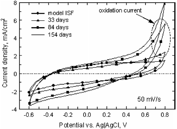
Representative 50 mV/s CVs in model ISF and in vivo at days 33, 84, and 154 postimplantation (array 12-1). The anodic and cathodic charge storage capacities increased with implantation time, and an irreversible oxidation process appeared at potentials above ~0.5 V.
At a sweep rate of 50 mV/s, the in vivo anodic and cathodic charge storage capacities of the electrodes on two of the three arrays (8-2 and 12-1) increased over the course of the implantation. The evolution of CSCc for the three arrays is shown in Fig. 4. The regression slopes and confidence intervals for CSCc and CSCa are provided in Table I. The 50 mV/s CSC of electrodes from array 9-1 did not change significantly with time in vivo (p > 0.05). Linear regression of the charge storage capacity over time for arrays 8-2 and 12-1 showed that the cathodic CSC increased by 0.118 and 0.064 mC/cm2·day, respectively. The irreversible oxidation reaction accounted for the larger relative increase in CSCa compared to CSCc.
Fig. 4.
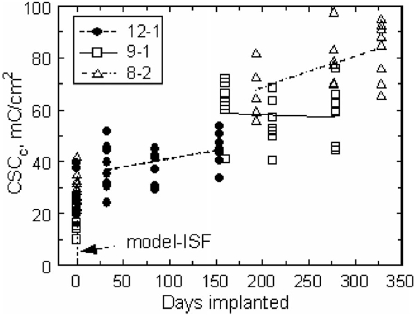
Cathodic charge storage capacities for each array in model ISF and in vivo (days 33–328) measured at 50 mV/s. The regression lines for arrays 12-1 and 8-2 indicate an increasing CSCc with implantation time. The regression for array 9-1 was not significantly different from zero.
TABLE I.
Regression Slopes (mC/cm2 -day) and 95% Confidence Intervals for CSCc and CSCa Measured at 50 mV/s
| Array | CSCc/CSCa | Slope | 95% Conf. Int. | p, % |
|---|---|---|---|---|
| 12-1 | CSCc | 0.064 | 0.005 / 0.124 | 0.03 |
| 12-1 | CSCa | 0.272 | 0.198 / 0.346 | <0.001 |
| 9-1 | CSCc | −0.015 | −0.116 / 0.087 | 0.769 |
| 9-1 | CSCa | 0.013 | −0.122 / 0.148 | 0.842 |
| 8-2 | CSCc | 0.118 | 0.029 / 0.208 | 0.013 |
| 8-2 | CSCa | 0.237 | 0.142 / 0.332 | <0.001 |
Changes in the CSCc measured at 50 000 mV/s are shown in Fig. 5. The CSC of the electrodes on all arrays decreased from preimplantation measurements in model ISF, which is expected due to higher resistivity and reduced ion transport in the fluid and tissue encapsulating the electrodes in vivo. The slopes of the CSCc and CSCa regression lines were not significantly different from zero for all three arrays. The oxidation reaction observed in the 50 mV/s CVs was not apparent at 50 000 mV/s.
Fig. 5.
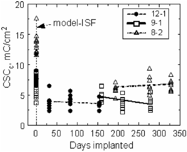
Cathodic charge storage capacities for each array in model ISF (day 0) and in vivo, measured at a sweep rate of 50 000 mV/s. The CSCa and CSCc are essentially equal at this sweep rate.
B. Impedance Spectroscopy
The effect of implantation on electrode impedance is illustrated by the Nyquist and Bode plots in Fig. 6. All measurements are from the same electrode, first in model ISF and then in vivo at days 33, 84, and 154. The model-ISF impedance is similar to that observed for metal electrodes in which the electrode–electrolyte interface can be represented by a constant phase element [20]. After implantation, all electrodes exhibited an increase in impedance and most developed a semicircular arc in their Nyquist plots. The in vivo impedance was similar to that observed by Williams et al. [21] with tungsten microelectrodes implanted in rat cortex for up to 20 days. The appearance of the arc reflects the introduction of an additional time constant for charge transfer in vivo and has been attributed to biomolecule absorption and encapsulation of the electrode with poorly conductive tissue [20], [22]. Williams et al. [21] examined impedance spectroscopy and histology from the same electrodes and observed that electrodes exhibiting larger semicircular arcs in their Nyquist plots had more pronounced peri-electrode gliosis. In this study, the semicircular arc was largest on the first day of measurement (day 33) and similar to those reported by Williams et al. [21] although their data were acquired at shorter implant times. At the longer time points, days 84 and 154, the impedance decreased from the day 33 level, but remained substantially greater than in vitro. These data are also shown in a Bode plot of impedance magnitude versus frequency in Fig. 6(b) which more clearly illustrates the frequency dependence of the impedance changes.
Fig. 6.
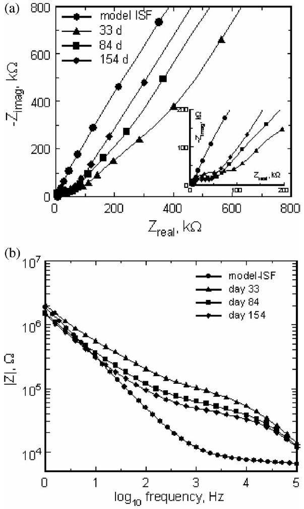
(a) Nyquist plot of the real and imaginary impedances of a single electrode in model ISF and at days 33, 84, and 154 postimplantation. The insert highlights the high-frequency shift to lower impedance with implantation time. (b) Bode plot of the same impedance data showing the impedance magnitude as a function of frequency.
Fig. 7 shows the 1 kHz impedance magnitude for all tested electrodes at all time points. There were no statistically significant trends in these data. The impedance of the electrodes on arrays 8-2 and 12-1 appeared to decrease with implantation time as shown by the regression lines in Fig. 7 (−0.1 kΩ/day (p = 0.16) and −0.27 kΩ/day (p = 0.21), respectively). While not significant, these trends are consistent with the observed increase in CSC of the electrodes (see Figs. 4 and 5). The impedance of array 9-1 increased with a slope of 0.24 kΩ/day (p = 0.09).
Fig. 7.
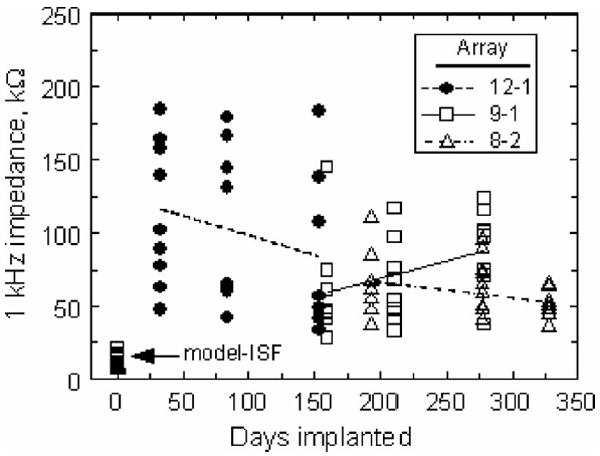
Effect of implantation time on the 1 kHz impedance magnitude. The regression lines suggest trends in the data but are not statistically significant.
Scanning electron microscopy of explanted arrays showed cracking of the Parylene insulation at the base of the electrode shafts (see Fig. 8). These cracks were most apparent on arrays 12-1 and 8-2, which exhibited an increase in CSC and a decrease in impedance. The trend in impedance is similar to that observed by Rousche and Normann, which they also attributed to degradation of the insulating material [23]. On array 9-1, cracks were visible, but less prominent. The electrode shown in Fig. 8 exhibited a 50 mV/s CSCc of 95 mC/cm2 at day 328 in vivo compared with a model-ISF CSCc of 32 mC/cm2. Consistent with the model that leakage pathway effects are highly dependent on frequency [10], [24], the 50 000 mV/s CSCc showed the opposite behavior, decreasing from 15 mC/cm2 in model ISF to 7 mC/cm2 in vivo (day 328). Examination of arrays that had not been implanted revealed no evidence of the cracking observed in the explanted arrays.
Fig. 8.
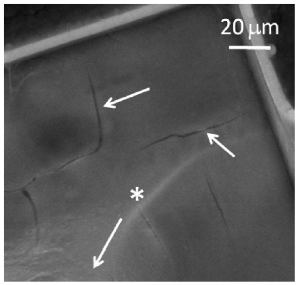
SEM image of insulation cracks at the base of an electrode shaft from array 8-2 implanted for 537 days. The arrow with the * label points longitudinally along the electrode shaft to the tip.
C. Voltage Transients
Fig. 9 shows the values of Emc for all implanted electrodes as the implantations progressed. The potential for reduction of water on SIROF is shown by the dashed line at −0.6 V.
Fig. 9.
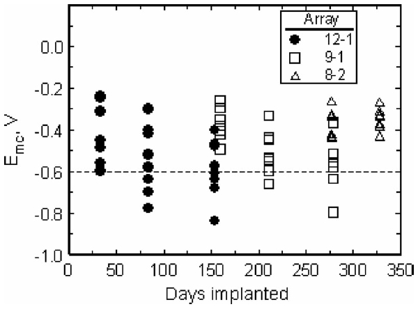
Effect of implantation time on Emc for electrodes pulsed at 8 nC/ph. The potential for reduction of water on SIROF is shown by the dashed line at −0.6 V.
Since many electrodes approached or exceeded the water reduction potential when pulsed at 8 nC/phase using a 0.0 V interpulse bias, a study was performed on three electrodes at day 154 to quantify the effects of interpulse bias from 0.0 to 0.6 V. The use of an anodic bias in the interpulse period is an established method of increasing the cathodal charge injection capacity of iridium oxide electrodes [13], although, to our knowledge, the effects of Vipp on charge injection capacity have not been reported for chronic in vivo studies.
As shown in Fig. 10, a more positive Vipp resulted in a substantial increase in charge capacity from 11.5 ± 2.2 nC/ph (0.58 ± 0.11 mC/cm2) at a 0.0 V bias to 21.8 ± 2.0 nC/ph (1.09 ± 0.1 mC/cm2) at 0.6 V. The charge capacity increased linearly with bias, with a slope of 16.3 nC/phase-V (R2 = 0.992) at a pulse width of 400 μs. However, as shown by the comparison in Fig. 10, the charge injection capacity in vivo was greatly reduced compared to SIROF microelectrodes tested in model ISF [16]. Using the Emc = −0.6 V (versus Ag∣AgCl) criterion, the maximum charge capacity in vivo was reduced by a factor of 2–3, with the larger reduction observed at more positive bias levels. At day 154 postimplantation, the mean open-circuit potential of the SIROF electrodes on this array was 0.006 ± 0.033 V (n = 8), suggesting that without active control of the interpulse bias, the maximum in vivo charge injection capacity for a 400 μs pulse, with these microelectrodes, will be less than 12 nC/ph (0.6 mC/cm2).
Fig. 10.
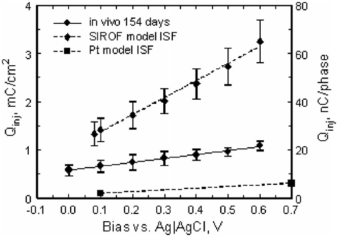
Effect of interpulse bias on the maximum charge injection capacity of SIROF electrodes pulsed cathodally with 400 μs current pulses. The plot shows the mean and standard deviation of measurements made on three electrodes from the same array at day 154 in vivo, along with linear fits to the data. Model-ISF data for SIROF [16] and Pt [25] are included for comparison.
The effect of pulse width on charge injection capacity at bias levels of 0.0 and 0.6 V is shown in Fig. 11 for the same three electrodes. For both bias levels, the maximum charge injection capacity increased by approximately 50% as the pulse width was increased from 150 to 500 μs, which is similar to results reported for SIROF in buffered physiological saline [13].
Fig. 11.
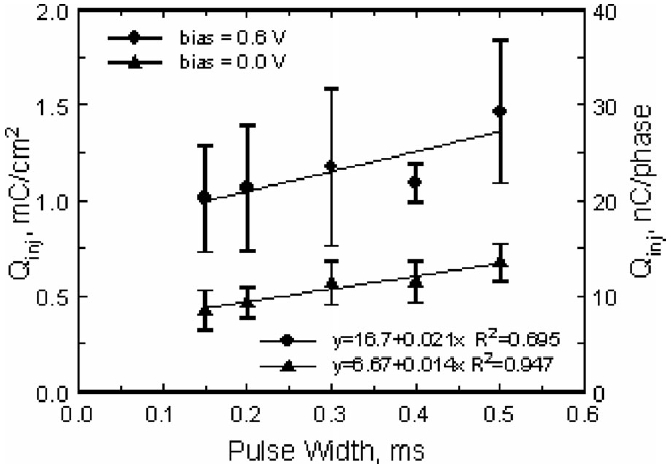
Effect of pulse width on the maximum charge injection capacity of SIROF electrodes pulsed cathodally with an interpulse bias of 0.0 and 0.6 V versus Ag∣AgCl. The plot shows the mean and standard deviation of measurements made on three electrodes from the same array at day 154 in vivo, along with linear fits to the data.
IV. Discussion
CV at 50 mV/s showed that the charge storage capacity of two of the arrays increased linearly with time over 11 months in vivo. The increase in CSCc and CSCa appears to result from the formation of leakage pathways through extensive cracks in the Parylene insulation, which were visualized by SEM after the arrays were explanted. Other mechanisms that might result in increased CSC, such as deterioration of the bulk insulating properties of polymer encapsulants due to water absorption, separation of the Parylene from the SIROF at the electrode tip, or leakage between conductors in the cable between the electrode array and head connector, cannot be excluded. The linear increase in CSC over time suggests that the leakage pathways were forming throughout the implantation period, implying that the cracking was an ongoing process that started soon after implantation. Since there are no SEM data for shorter implantation times, we cannot confirm that cracking occurred before day 225, the earliest explanation time (array 12-1).
There was considerable intraarray variation in the 1 kHz in vivo impedance data. This variation was not observed in vitro and, therefore, may suggest that different tissue responses occurred around different electrodes, a result that has been observed before [21]. As a result of this variation, the decrease in impedance was not statistically significant for either array 8-2 or 12-1. The observed trends in impedance and CSC are consistent with the hypothesis that the available surface area for the electrodes on these arrays is increasing with implantation time.
The charge storage capacities and 1 kHz impedance for array 9-1 did not show a statistically significant dependence on implantation time. This result is consistent with the qualitative observation by SEM that cracking in the Parylene insulation was least evident on array 9-1, although not absent. The observation also suggests that the changes in the electrochemistry of arrays 8-2 and 12-1 are not due to changes in the SIROF electrode coating, which was the same for all three arrays.
Voltage transients in response to 8 nC/phase pulsing on array 12-1, represented by Emc, increased in magnitude from day 33 to day 154 (see Fig. 9). There was a corresponding increase in the percentage of tested electrodes that exceeded the −0.6 V water electrolysis limit, reaching a maximum of 50% of eight electrodes pulsed on array 12-1 on day 154. For array 8-2 which was examined only at longer implantation periods, Emc was less negative and no electrodes on this array exceeded the safe stimulation threshold when delivering 8 nC/phase at days 277 and 328. Array 9-1, which did not exhibit evidence of current leakage in CV and impedance measurements, showed a negative shift in Emc between days 160 and 279, suggesting a decrease in charge injection capacity for the electrodes on this array. We suspect that arrays 8-2 and 12-1 represent electrodes with charge-injection capacities that increase after about day 150 due to leakage pathways; however, the Emc data are sparse, and the results are, therefore, not definitive. Likewise, the increasingly negative Emc observed with array 9-1 requires a longer measurement time to establish the trend with confidence.
The current pulsing measurements at day 154 on array 12-1 showed that the charge injection capacity increased linearly with both bias and pulse width, suggesting that either approach could be used to overcome the loss in charge injection capacity in brain tissue. A concern, however, with the charge injection results is the likelihood that a portion of the current delivered during pulsing is shunted to tissue through a pathway other than the intended electrode. The extent to which this happens cannot be determined from these data, but any current shunting results in an overestimation of the in vivo charge injection capacity of the electrodes, which is already significantly reduced compared with model-ISF values.
Although this study included only three arrays with a total of 48 electrodes, four additional arrays, coated with PEG-PLA or PEG-PLA and nerve growth factor, were also evaluated. The CV and impedance results for the additional arrays, which will be presented separately, showed very similar long-term trends. Endpoint histology and neural recording results from these animals may offer additional insight into the chronic response and performance of the arrays.
V. Conclusion
Electrochemical characterization of SIROF-coated penetrating microelectrode arrays implanted in cat cortex for up to 328 days showed large changes in device performance and variability among electrodes and electrode arrays. The variability was attributed, at least in part, to cracking of Parylene insulation, which may be responsible for the near linear increase in charge storage capacity observed with implantation time. The cracking is presumed to result in current leakage pathways that increase the effective area of the electrodes. While most electrodes were capable of injecting 8 nC/phase, well above expected functional thresholds for cortical stimulation with indwelling microelectrodes [4], [5], the leakage clearly shunts a portion of the imposed current to tissue via pathways other than the intended electrode tip. This results in an overestimation of the charge injection capabilities of the electrodes. The modest charge injection capacity of these electrodes compared to in vitro values reflects the importance of in vivo characterization and the need to more fully understand mechanisms by which the tissue environment reduces the charge-injection capabilities of stimulation electrodes.
In planning future studies, it is essential to improve the mechanical and electrical stability of multielectrode arrays to avoid the confounding effects of electrical leakage pathways on the determination of the electrochemical properties and functional performance of electrodes implanted for long periods. For this study, the contribution of leakage current pathways undoubtedly limits the interpretation of the data. It is suspected that other researchers, performing long-term chronic recording and stimulation studies, will experience difficulty with interpretation of experimental results due to hardware reliability issues. It is important to note that while deterioration of the implanted devices, in this study, was evident, robust single-unit recordings were obtained throughout the respective implantation periods for all three arrays for which data are reported.
Acknowledgments
This work was supported by the National Institutes of Health under Grant 5R44NS49687-3.
Biography
Sheryl R. Kane (M’11) received the B.A. degree in chemistry from Johns Hopkins University, Baltimore, MD, USA, in 2002, and the Ph.D. degree in bioengineering from UC Berkeley/UC San Francisco, USA, in 2008.
Her main areas of interest in biomedical research include surface modification of medical devices and drug delivery. She has studied lubricious coatings for total hip replacements, biocompatible coatings for subretinal electrode arrays, and coatings that elute growth factors from the tips of cortical electrode arrays. She is currently a Senior Scientist at Clean Membranes working on fouling-resistant membranes for water filtration.

Stuart F. Cogan (M’95) received the B.Sc. degree in mechanical engineering and the M.S. degree in materials science from Duke University, Durham, NC, USA, in 1975 and 1977, respectively. He received the Sc.D. degree in materials science from the Massachusetts Institute of Technology, Cambridge, MA, USA, in 1979.
He is currently a Director of Advanced Materials Research at EIC Laboratories, Inc., Norwood, MA, USA. His research interests include thin-film electrochromics for optical switching devices, materials for encapsulating implanted medical devices, and electrode materials for stimulation and recording in prosthetic and pacing applications.

Julia Ehrlich received the M.S. degree in materials science from the Institute of Fine Chemical Technology, Moscow, Russia, in 1991.
She is currently a Staff Scientist at EIC Laboratories in 1993 after working for one year at the ETEX Corporation. Her research interests include the development of electrodeposition processes for electroactive coatings, and the characterization of coatings by electrochemical and electron microscopy techniques.
Timothy D. Plante received the B.Sc. degree in chemistry from Providence College, Providence, RI, USA, in 1983.
He is currently a Staff Scientist at EIC Laboratories Inc., Norwood, MA, USA. His work has focused on the development of thin film deposition processes and the electrochemical characterization of materials for implantable medical electrodes and optical switching devices, with an emphasis on the development and testing of electrode coatings for use in neural recording and stimulation.
Douglas B. McCreery (M’12) received the B.Sc. and M.Sc. degrees in electrical engineering and the Ph.D. degree in biomedical engineering from the University of Connecticut, Storrs-Mansfield, CT, USA, in 1966, 1970, and 1975, respectively.
After completing a postdoctoral fellowship in the Department of Neurosurgery at the University of Minnesota, he moved to the Huntington Medical Research Institutes, Pasadena, CA, USA, where he is currently the Director of the Neural Engineering Program. His research interests include the development of neuroprostheses for the central nervous system, and the physiologic and histologic effects of electrical stimulation of the central and peripheral nervous system.

Philip R. Troyk (SM’91) received the B.S.E.E. degree from the University of Illinois at Urbana-Champaign, Urbana, IL, USA, in 1974, the M.S.Bio.E. degree from the University of Illinois, Chicago, in 1980, and the Ph.D. degree in bioengineering from the University of Illinois at Chicago, Chicago, USA, in 1983.
In 1983, he joined the faculty of the Illinois Institute of Technology (IIT). Prior to that time, he was on the engineering staff of Northrop Corp. Defense Systems Division. Since joining IIT, he has been with the Department of Electrical and Computer Engineering, Pritzker Institute of Biomedical Science and Engineering, and most recently with the Department of Biomedical Engineering. He is a Director of neural engineering at IIT and performs research on a broad range of topics including neural prostheses, visual prostheses, and implantable sensors for control of prosthetic limbs.

Contributor Information
Sheryl R. Kane, EIC Laboratories, Norwood, MA 02062 USA. She is now with Clean Membranes, Tyngsboro, MA 01978 USA.
Stuart F. Cogan, EIC Laboratories, Norwood, MA 02062 USA.
Julia Ehrlich, EIC Laboratories, Norwood, MA 02062 USA.
Timothy D. Plante, EIC Laboratories, Norwood, MA 02062 USA
Douglas B. McCreery, Huntington Medical Research Institutes, Pasadena, CA 91105 USA.
Philip R. Troyk, Illinois Institute of Technology, Chicago, IL 60616 USA.
References
- [1].Polikov VS, Tresco PA, and Reichert WM, “Response of brain tissue to chronically implanted neural electrodes,” J. Neurosci. Methods, vol. 148, pp. 1–18, October 2005. [DOI] [PubMed] [Google Scholar]
- [2].McCreery DB, Agnew WF, and Bullara LA, “The effects of prolonged intracortical microstimulation on the excitability of pyramidal tract neurons in the cat,” Ann. Biomed. Eng, vol. 30, pp. 107–119, 2002. [DOI] [PubMed] [Google Scholar]
- [3].McCreery DB, Yuen TGH, and Bullara LA, “Chronic microstimulation in the feline ventral cochlear nucleus: Physiologic and histologic effects,” Hear. Res, vol. 149, pp. 223–238, 2000. [DOI] [PubMed] [Google Scholar]
- [4].Schmidt EM, Bak MJ, Hambrecht FT, Kufta CV, O’Rourke DK, and Vallabhanath P, “Feasibility of a visual prosthesis for the blind based on intracortical microstimulation of the visual cortex,” Brain, vol. 119, pp. 507–522, 1996. [DOI] [PubMed] [Google Scholar]
- [5].McCreery D, Pikov V, and Troyk PR, “Neuronal loss due to prolonged controlled-current stimulation with chronically implanted microelectrodes in the cat cerebral cortex,” J. Neural Eng, vol. 7, pp. 1–16, 2010. [DOI] [PMC free article] [PubMed] [Google Scholar]
- [6].Henze DA, Borhegyi Z, Csicsvari J, Mamiya A, Harris KD, and Buzsaki G, “Intracellular features predicted by extracellular recordings in the hippocampus in vivo,” J. Neurophysiol, vol. 84, pp. 390–400, 2000. [DOI] [PubMed] [Google Scholar]
- [7].Grill WM, Norman SE, and Bellamkonda RV, “Implanted neural interfaces: Biochallenges and engineered solutions,” Annu. Rev. Biomed. Eng, vol. 11, pp. 1–24, 2009. [DOI] [PubMed] [Google Scholar]
- [8].Biran R, Martin DC, and Tresco PA, “Neuronal cell loss accompanies the brain tissue response to chronically implanted silicon microelectrode arrays,” Exp. Neurol, vol. 195, pp. 115–126, 2005. [DOI] [PubMed] [Google Scholar]
- [9].Merrill DR and Tresco PA, “Impedance characterization of microarray recording electrodes in vitro,” IEEE Trans. Biomed. Eng, vol. 52, no. 11, pp. 1960–1965, November 2005. [DOI] [PubMed] [Google Scholar]
- [10].Cogan SF, “Neural stimulation and recording electrodes,” Annu. Rev. Biomed. Eng, vol. 10, pp. 275–309, 2008. [DOI] [PubMed] [Google Scholar]
- [11].Normann RA, Maynard EM, Rousche PJ, and Warren DJ, “A neural interface for a cortical vision prosthesis,” Vis. Res, vol. 39, pp. 2577–2587, 1999. [DOI] [PubMed] [Google Scholar]
- [12].Nordhausen CT, Maynard EM, and Normann RA, “Single unit recording capabilities of a 100 microelectrode array,” Brain Res, vol. 726, pp. 129–140, 1996. [PubMed] [Google Scholar]
- [13].Cogan SF, Ehrlich J, Plante TD, Smirnov A, Shire DB, Gingerich M, and Rizzo JF, “Sputtered iridium oxide films for neural stimulation electrodes,” J. Biomed. Mater. Res. B, Appl. Biomater, vol. 89B, pp. 353–361, 2009. [DOI] [PMC free article] [PubMed] [Google Scholar]
- [14].Bhandari R, Negi S, Rieth L, and Solzbacher F, “A wafer-scale etching technique for high aspect ratio implantable MEMS structures,” Sens. Actuators A, Phys, vol. 162, pp. 130–136, 2010. [DOI] [PMC free article] [PubMed] [Google Scholar]
- [15].Campbell PK, Jones KE, Huber RJ, Horch KW, and Normann RA, “A silicon-based, 3-dimensional neural interface—manufacturing processes for an intracortical electrode Array,” IEEE Trans. Biomed. Eng, vol. 38, no. 8, pp. 758–768, August 1991. [DOI] [PubMed] [Google Scholar]
- [16].Cogan SF, Ehrlich J, Plante TD, and Van Wagenen R, “Penetrating microelectrode arrays with low-impedance sputtered iridium oxide electrode coatings,” in Proc. Annu. Int. Conf. IEEE Eng. Med. Biol. Soc, 2009, pp. 7147–7150. [DOI] [PMC free article] [PubMed] [Google Scholar]
- [17].Cogan SF, Troyk PR, Ehrlich J, Gasbarro CM, and Plante TD, “The influence of electrolyte composition on the in vitro charge-injection limits of activated iridium oxide (AIROF) stimulation electrodes,” J. Neural Eng, vol. 4, pp. 79–86, 2007. [DOI] [PubMed] [Google Scholar]
- [18].Bard AJ and Faulkner LR, Electrochemical Methods: Fundamentals and Applications, 2nd ed. Hoboken, NJ, USA: Wiley, 2001, pp. 27–28. [Google Scholar]
- [19].Troyk PR, Detlefsen DE, Cogan SF, Ehrlich J, Bak M, McCreery DB, Bullara L, and Schmidt E, ““Safe” charge-injection waveforms for iridium oxide (AIROF) microelectrodes,” in Proc. 26th Annu. Int. Conf. IEEE Eng. Med. Biol. Soc, 2004, vol. 2, pp.4141–4144. [DOI] [PubMed] [Google Scholar]
- [20].Lempka SF, Miocinovic S, Johnson MD, Vitek JL, and McIntyre CC, “In vivo impedance spectroscopy of deep brain stimulation electrodes,” J. Neural Eng, vol. 6, pp. 1–13, 2009. [DOI] [PMC free article] [PubMed] [Google Scholar]
- [21].Williams JC, Hippensteel JA, Dilgen J, Shain W, and Kipke DR, “Complex impedance spectroscopy for monitoring tissue responses to inserted neural implants,” J. Neural Eng, vol. 4, pp. 410–423, 2007. [DOI] [PubMed] [Google Scholar]
- [22].Mercanzini A, Colin P, Bensadoun JC, Bertsch A, and Renaud P, “In Vivo electrical impedance spectroscopy of tissue reaction to microelectrode arrays,” IEEE Trans. Biomed. Eng, vol. 56, no. 7, pp. 1909–1918, July 2009. [DOI] [PubMed] [Google Scholar]
- [23].Rousche PJ and Normann RA, “Chronic recording capability of the Utah Intracortical Electrode Array in cat sensory cortex,” J. Neurosci. Methods, vol. 82, pp. 1–15, 1998. [DOI] [PubMed] [Google Scholar]
- [24].Twardoch UM, “Integrity of ultramicro-stimulation electrodes determined from electrochemical measurements,” J. Appl. Electrochem, vol. 24, pp. 835–857, 1994. [Google Scholar]
- [25].Cogan SF, Troyk PR, Ehrlich J, and Plante TD, “In vitro comparison of the charge-injection limits of activated iridium oxide (AIROF) and platinum-iridium microelectrodes,” IEEE Trans. Biomed. Eng, vol. 52, no. 9, pp. 1612–1614, September 2005. [DOI] [PubMed] [Google Scholar]


